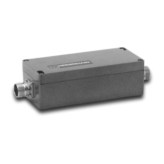
Inhaltszusammenfassung für HEIDENHAIN IBV 600
- Seite 1 HEIDENHAIN Betriebsanleitung Operating Instructions IBV 600 IBV 610 IBV 625 IBV 650 IBV 660 B 12/2002...
- Seite 2 Technische Beschreibung/Lieferumfang Technical Description/Items Supplied ˜ Lieferumfang Items Supplied • • • • Stecker und Kabel Connectors and Cable • • ZubehÛr fár Justage und Service (separat zu bestellen) Accessories for Adjustment and Service (must be ordered • separately) •...
- Seite 3 Contents Page IBV Input Signals IBV Output Signals (TTL) IBV Settings ˜...
- Seite 4 IBV 600 ï Overview Model Interpolation Clock frequency f Input frequency f Min. edge separation a ˜ ˜ ˜ ˜ ˜ ˜...
- Seite 5 Mounting Select the proper mounting location ‘ ‘ • • • • • • ‘ ‘ Cable Permissible bending radius for diameter frequent flexing rigid configuration Mechanical data Weight Protection Operating temperature Storage temperature Vibration Shock...
- Seite 6 Mechanischer Anbau ï Hauptabmessungen Mounting ï Overall Dimensions M4 x 20 ISO 4762 HEIDENHAIN 163±0.2 ‘ Die IBV mit zwei Befestigungsschrauben M4 ¼ 20 DIN 912 ‘ Mount the IBV with two mounting screws montieren. M4 ¼ 20 ISO 4762.
- Seite 7 Electrical Connection Use the proper cable: ‘ ‘ ‘ ‘ ‘ ‘ Encoder to IBV > 4.75 V ˜ ˜ ˜ ˜ > 4.9 V IBV to subsequent electronics Grounding and shielding ∅ ‘ € ‘ € ‘ ‘...
- Seite 8 Cable Overview...
- Seite 9 Power Supply Voltage Current consumption IBV 600 IBV 610 IBV 625 IBV 650 IBV 660 B WARNING ï Potential Damage to Internal Parts Power sources must conform to EN 50 178 (safety isolating transformers with protective low voltage) Do not open the housing or engage or disengage...
- Seite 10 IBV Input Signals Signal levels Input frequency f Current consumption of the connected encoders Pin layout (colors specified as they apply to HEIDENHAIN cable) ˜ ˜ ˜ ˜ Color...
- Seite 11 IBV Input Signals...
- Seite 12 IBV 610/625/650/660 B: clocked ˜ Min. edge separation ˜ Min. pulse width ˜ IBV 600: non-clocked ˜ ˜ Min. edge separation a = 0.2 šs ˜ ˜ ˜ Reference pulse: Width Width Fault detection signal: ˜...
- Seite 13 IBV Output Signals (TTL) IBV 600/IBV 610 IBV 625/IBV 650 IBV 660 B...
- Seite 14 IBV Output Signals (TTL) Signal levels Load capacity Short-circuit stability Switching times...
- Seite 15 IBV Output Signals (TTL) Pin layout (colors specified as they apply to HEIDENHAIN cable) Color...
- Seite 16 IBV Output Signals (TTL) Permissible cable length from IBV to subsequent electronics − − − − ≤ ≤ Recommended input circuitry of subsequent electronics + 5 V AM 26 LS 32 SN75ALS193 MC 3486 SN75ALS195 RS - 422 DIN 66 259 + 5 V U aS AM 26 LS 32...
- Seite 17 IBV Output Signals (TTL) Minimum edge separation a /Minimum pulse width b clocked...
- Seite 18 Settings for IBV 600...
- Seite 19 Settings for IBV 600 ˜ Reference pulse width Switches Outputs: ˜˜˜ Switches ˜ † † † †...
- Seite 20 Settings IBV 610...
- Seite 21 Settings IBV 610 ˜ Reference pulse width ˜ Switches ˜ Outputs: ˜˜˜ Switches ˜ ˜ ˜˜n¬@˜Fd † ˜ † Inter- Clock Max. input Min. edge Min. pulse Switches polation frequency separation a width b † † † † † † †...
- Seite 22 Settings IBV 625...
- Seite 23 Settings IBV 625 Reference pulse width Switches Outputs: ˜˜˜ Switches ˜ hysteresis for incremental signals † † † Interpolation Clock Max. input Min. edge Min. pulse Switches frequency separation a width b † † † † † †...
- Seite 24 Settings IBV 650...
- Seite 25 Settings IBV 650 Reference pulse width Switches Outputs: ˜˜˜ Switches ˜ hysteresis for incremental signals † † † Interpolation Clock Max. input Min. edge Min. pulse Switches frequency separation a width b † † † † † †...
- Seite 26 Settings IBV 660 B Adjusting the IBV • • • • • • • • • • • •...
- Seite 27 Settings IBV 660 B Reference pulse width Switches Outputs: ˜˜˜ Switches † † Min. edge separation a min Switches Hysteresis for incremental signals Switches † † † † † Interpolation Max. input frequency Switches † † † † † † †...
- Seite 28 DR. JOHANNES HEIDENHAIN GmbH Dr.-Johannes-Heidenhain-Straße 5 83301 Traunreut, Germany { +49/86 69/31-0 | +49/86 69/50 61 E-Mail: info@heidenhain.de Technical support | +49/86 69/10 00 Measuring systems { +49/86 69/31-31 04 E-Mail: service.ms-support@heidenhain.de TNC support { +49/86 69/31-31 01 E-Mail: service.nc-support@heidenhain.de...


