Inhaltsverzeichnis
Werbung
Verfügbare Sprachen
Verfügbare Sprachen
Quicklinks
SITRANS TF
Transmitter for temperature
Instruction Manual / Betriebsanleitung
Messumformer für Temperatur
7NG313x
Deutsch
. . . . . . . . . . . . . . . . . . . . . . . . . . . . . . . . . . . . . . . . . . . . . . . . . . . . . . . . . . . . . . . . . . . .
English
. . . . . . . . . . . . . . . . . . . . . . . . . . . . . . . . . . . . . . . . . . . . . . . . . . . . . . . . . . . . . . . . . . . .
Edition 03/2002
Page 21
Seite 1
Werbung
Kapitel
Inhaltsverzeichnis

Verwandte Anleitungen für Siemens 7NG313x


Inhaltszusammenfassung für Siemens 7NG313x
- Seite 1 Edition 03/2002 Messumformer für Temperatur 7NG313x Deutsch ..............
-
Seite 3: Inhaltsverzeichnis
............Copyright e Siemens AG 1999 All rights reserved Haftungsausschluss Weitergabe sowie Vervielfältigung dieser Anleitung,... -
Seite 4: Klassifierzung Der Sicherheitshinweise
SITRANS TF Betriebsanleitung Klassifierzung der Sicherheitshinweise Diese Anleitung enthält Hinweise, die Sie zu Ihrer persönlichen Sicherheit sowie zur Vermeidung von Sach- schäden beachten müssen. Die Hinweise sind durch ein Warndreieck hervorgehoben und je nach Gefähr- dungsgrad folgendermaßen dargestellt: GEFAHR bedeutet, dass Tod oder schwere Körperverletzung eintreten wird, wenn die entspre- chenden Vorsichtsmaßnahmen nicht getroffen werden. -
Seite 5: Allgemeine Hinweise
Betriebsanleitung SITRANS TF Allgemeine Hinweise WARNUNG Der einwandfreie und sichere Betrieb dieses Gerätes setzt sachgemäßen Transport, fachgerechte Lagerung und Montage sowie sorgfältige Bedienung und Instandhaltung voraus. Dieses Gerät darf nur von qualifiziertem Personal montiert und betrieben wer- den. In dieser Anleitung befinden sich Informationen zum Standardanschluss der Sensor Signalleitungen im stromlosen Zustand. -
Seite 6: Strommessung
SITRANS TF Betriebsanleitung Potentiome- Widerstand Keine Kompensation Keine Kompensation Dreileiter Kompensation für Dreileiter Leitungskompensa- Übertratungswiderstand tion Vierleiter Kompensation für Vierleiter Leitungskompensa- Leitungs- und Übertratungswi- tion derstand Strommessung Spannungsmessung Widerstand zwischen Widerstandsanfang und Schleifer. Leitungswiderstand zur Korrektur ist programmierbar. Bild 1: Sensoranschlussbelegung des Messumformers (Fortsetzung) A5E00046014-07... -
Seite 7: Technische Beschreibung
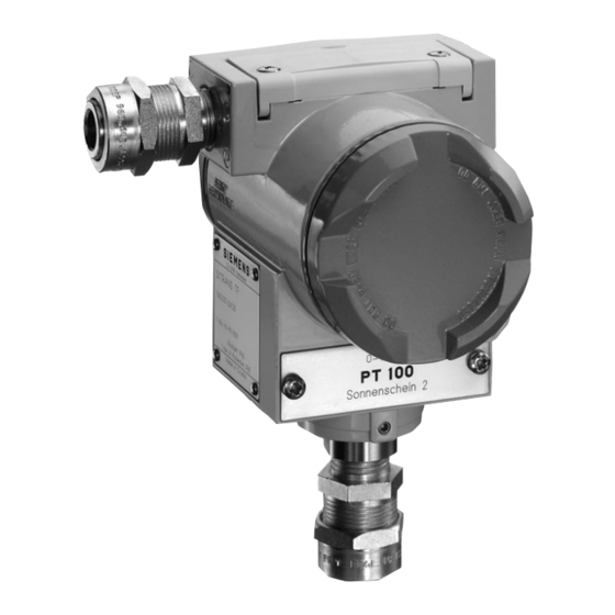
Betriebsanleitung SITRANS TF Technische Beschreibung Bild 2 Messumformer für Temperatur SITRANS TF Anwendungsbereich Der Messumformer SITRANS TF formt das Signal von Widerstandsthermometern, Widerstandsgebern, Thermoelementen oder Spannungsgebern in ein der Sensorkennlinie entsprechendes eingeprägtes Gleichstromsignal um. Die Kommunikationsfähigkeit (HARTR-Protokoll V 5.7) des SITRANS TF mit eingebautem SITRANS TK-H ermöglicht eine Parametrierung mit PC oder HART-Communicator (Hand-Held-Communicator). -
Seite 8: Technische Daten
SITRANS TF Betriebsanleitung SITRANS TF Hilfsenergie 0000 SITRANS TK-H Sensor Bürde μP 1 Analog-/Digital-Umsetzer 2 Galvanische Trennung 3 Mikroprozessor 4 Digital-/Analog-Umsetzer 5 Hilfsenergiequelle (z. B. Speisetrenner) 6 PC/Laptop 7 HART-Modem 8 Digitalanzeiger (Option) 9 Testbuchsen Bild 3 Blockschaltbild Funktionsweise des SITRANS TF mit eingebautem SITRANS TK-H und Digital- anzeiger Technische Daten Eingang... -
Seite 9: Einsatzbedingungen Umgebungsbedingungen
Betriebsanleitung SITRANS TF Ausgang Ausgangssignal 4 bis 20 mA, Zweileiter Kommunikation bei SITRANS TK-H nach HART V 5.7 Messgenauigkeit Digitaler Messfehler Widerstandsgeber Eingang Messbereich W Min. Messspanne W Dig. Genauigkeit W -- Widerstand 0 bis 390 0,05 -- Widerstand 0 bis 2200 0,25 Widerstandsthermometer Eingang... - Seite 10 SITRANS TF Betriebsanleitung Konstruktiver Aufbau Gewicht etwa 1,5 kg (ohne Optionen) Maße siehe Bild 4, Seite 9 Gehäusewerkstoff Kupferarmer Aluminiumdruckguss GD--AISi 12, Lack auf Polyesterbasis, Typenschild aus Edel- stahl Elektrischer Anschluss, Sensoranschluss Schraubklemmen, Kabeleinführung über Ver- schraubung M20x1,5 oder ½--14 NPT Montagewinkel (Option) Stahl, verzinkt und gelbchromatiert oder Edel- stahl...
- Seite 11 Betriebsanleitung SITRANS TF Kommunikation · Bürde bei HART--Anschluss 230 bis 1100 W · Leitung zweiadrig geschirmt: 3 km ≤ mehradrig geschirmt: 1,5 km ≤ · Protokoll HART-Protokoll V 5.x max. 164 (M20 x 1,5) max. 189 (½- -14 NPT) max. 25 (M20 x 1,5) max.
-
Seite 12: Bestelldaten
SITRANS TF Betriebsanleitung Bestelldaten Bestell-Nr. Temperaturmessumformer im Feldgehäuse 7NG313j- -jjjjj Zweileitertechnik 4 bis 20 mA, mit galvanischer Trennung Eingebauter Messumformer · ohne Messumformer -- ohne Messumformer, mit EEx ia -- ohne Messumformer, mit EEx n (Zone 2) -- ohne Messumformer, Gesamtgerät SITRANS TF EEx d ·... - Seite 13 Betriebsanleitung SITRANS TF Zubehör/Ersatzteile (falls erforderlich) Bestell-Nr. SIPROM TK Parametriersoftware für SITRANS TK (deutsch/englisch) 7NG3190- -8KB Modem für SITRANS TK 7NG3190- -6KB Betriebsanleitung SITRANS TK/TK--H deutsch/englisch (nicht im Lieferumfang des Gerätes enthalten) C79000- -B7174- -C12 SIMATIC PDM Parametriersoftware (auch für SITRANS TK--H) 7MP5000- -0AA00- -0AA0 Koppelmodul (HART-Modem) für SIMATIC PDM...
-
Seite 14: Elektrischer Anschluss Der Stromversorgung
SITRANS TF Betriebsanleitung Zubehör/Ersatzteile (falls erforderlich) Bestell-Nr. Eingebauter SITRANS TK · bei 7NG3131 --0... 7NG3120- -1JN00 · --1... 7NG3122- -1JN00 · --2... 7NG3121- -1JN00 · --4... 7NG3120- -1JN00 Eingebauter SITRANS TK- -H · bei 7NG3132 --0... 7NG3120- -2JN00 · --1... 7NG3122- -2JN00 ·... -
Seite 15: Digitalanzeiger Dvm-Lcd
Betriebsanleitung SITRANS TF WARNUNG Die Betriebsanleitung für SITRANS TK/TK-H, Bestellnr. C79000-B7174-C12 sowie die Bedie- nungsanleitung für Digitalanzeiger DVM-LCD 7MF4997--1BS sind zu beachten! Bei eingebautem SITRANS TK erfolgt die Programmierung direkt an den Klemmen des SITRANS TK. Bei Austausch der Kabelverschraubung bzw. Blindstopfen dürfen nur solche verwendet wer- den, die der in der EG-Baumusterprüfbescheinigung festgelegten Zündschützart bescheinigten Komponente (”Druckfeste Kapselung”... -
Seite 16: Einbau
SITRANS TF Betriebsanleitung Einbau: 1. Vorderen Deckel abschrauben. 2. Mitgelieferte Abstandsstücke in das rechte und linke Gewinde einschrauben (Anziehungsmoment ca. 3 Nm). 3. Linke Kurzschlussbrücke auf der Leiterplatte, die sich unterhalb des Messumformers befindet, entfer- nen. 4. Steckverbinder des Digitalanzeigers einstecken, beachten Sie, dass die Plus--Seite (farbige Leitung) nach oben zeigt, prüfen Sie, ob die Digitalanzeige funktioniert, wenn nicht polen Sie den Steckverbinder um (es besteht ein Verpolungsschutz), siehe Bild 6. -
Seite 17: Anhang: Zertifikate
Betriebsanleitung SITRANS TF Anhang: Zertifikate A5E00046014-07... - Seite 18 SITRANS TF Betriebsanleitung A5E00046014-07...
- Seite 19 Betriebsanleitung SITRANS TF A5E00046014-07...
- Seite 20 SITRANS TF Betriebsanleitung A5E00046014-07...
- Seite 21 Betriebsanleitung SITRANS TF A5E00046014-07...
- Seite 22 SITRANS TF Betriebsanleitung A5E00046014-07...
- Seite 23 ............Copyright e Siemens AG 1999 All rights reserved...
-
Seite 24: Classification Of Safety-Related Notices
SITRANS TF Instruction Manual Classification of Safety-Related Notices These instructions contain notices which you should observe to ensure your own personal safety, as well as to protect the product and connected equipment. These notices are highlighted in the instructions by a warning triangle and are marked as follows accoding to the level of danger: DANGER indicates an imminently hazardous situation which, if not avoided, will result in... -
Seite 25: General Information
Instruction Manual SITRANS TF General Information WARNING indicates a potentially hazardous situation which, if not avoided, could result in death or serious injury. Trouble-free and reliable operation of this device is conditional upon the proper storage and assembly as well as careful operation and maintenance. This device may only be assembled and operated by specialized personnel. -
Seite 26: Current Measurement
SITRANS TF Instruction Manual Potentiometer Resistance No compensation No compensation Three-wire compensation for Three-wire line compensation transfer resistance Four-wire compensation for Four-wire line compensation line and transfer resistance Current measurement Voltage measurement Resistance between start of resistance and sliding contact. Line resistance for compensation is programmable. -
Seite 27: Technical Description
Instruction Manual SITRANS TF Technical Description Figure 2 Transmitter for temperature SITRANS TF Range of Application The transmitter SITRANS TF transmits the signal of resistance thermometers, resistance based sensors, thermocouples or voltage sensors into an impressed direct current that corresponds to the sensor characteristics. -
Seite 28: Technical Data
SITRANS TF Instruction Manual SITRANS TF Auxiliary power 0000 SITRANS TK-H Sensor Load μP 1 Analog/digital converter 2 Electrical isolation 3 Microcontroller 4 Digital/analog converter 5 Auxiliary power source (e.g. isolating power supply) 6 PC/Laptop 7 HART modem 8 Digital display (Option) 9 Test connectors Figure 3 Block diagram of the mode of function of the SITRANS TF with in-built SITRANS TK-H and... - Seite 29 Instruction Manual SITRANS TF Output Output signal 4 to 20 mA, two wire Communication with SITRANS TK-H According to HART V 5.7 Measuring accuracy Digital measuring error Resistance-based sensor Input Measuring range W Min. measuring span W Dig. Accuracy W -- Resistance 0 to 390 0,05...
-
Seite 30: Electrical Isolation
SITRANS TF Instruction Manual Construction design Weight approx. 1,5 kg (without options) Dimensions see figure 4, page 29 Materials of the housing Low-copper die-cast aluminum GD--AISi 12, polyester-based lacquer, stainless-steel rating plate Electrical connection, sensor connection Screw terminals cable inlet via compression gland M20x1,5 or ½--14 NPT Mounting bracket (optional) Steel, galvanized and yellow-passivated or... - Seite 31 Instruction Manual SITRANS TF Hard and software requirements for the parameterization software SIPROM TK for SITRANS TK Personal computer IBM compatible, 486 or higher 3½”-diskette drives Hard disk with ca. 5 MB free memory at least 4 MB RAM working memory VGA graphics adapter (or compatible) with at least 16 colors One free serial interface...
-
Seite 32: Ordering Data
SITRANS TF Instruction Manual Ordering Data Order number Temperature transmitter in field hosuing 7NG313j- -jjjjj Two wire connection 4 to 20 mA, with electrical isolation Built-in transmitter · without transmitter --without transmitter, without explosion protection -- without transmitter, with EEx ia --without transmitter, with EEx n (zone 2) -- without transmitter, total device SITRANS TF EEx d ·... - Seite 33 Instruction Manual SITRANS TF Accessories/spare parts (if required) Order number SIPROM TK Parameterization software for SITRANS TK (german/english) 7NG3190- -8KB Modem for SITRANS TK 7NG3190- -6KB Instruction Manual SITRANS TK/TK--H german/english (not contained in scope of supply of the device) C79000- -B7174- -C12 SIMATIC PDM Parameterization software (also for SITRANS TK--H)
-
Seite 34: Electrical Connection Of The Power Supply
SITRANS TF Instruction Manual Accessories/spare parts (if required) Order number Built-in SITRANS TK · for 7NG3131 --0... 7NG3120- -1JN00 · --1... 7NG3122- -1JN00 · --2... 7NG3121- -1JN00 · --4... 7NG3120- -1JN00 Built-in SITRANS TK- -H · for 7NG3132 --0... 7NG3120- -2JN00 ·... -
Seite 35: Digital Display Dvm-Lcd
Instruction Manual SITRANS TF WARNING The Instruction manual for SITRANS TK/TK-H, order no. C79000-B7174-C12 as well as the Operating Manual for Digital Display DVM-LCD 7MF4997--1BS must be observed positively! With an installed SITRANS TK, programming is done directly at the terminals of the SITRANS TK. - Seite 36 SITRANS TF Instruction Manual Mounting: 1. Unscrew front cover. 2. Screw the supplied spacer bolts into the right and left screw threads (tightening torque ca. 3 Nm). 3. Remove the left--hand jumper on the PCB which is located under the transmitter. 4.
-
Seite 37: Appendix: Certificates
Instruction Manual SITRANS TF Appendix: Certificates A5E00046014-07... - Seite 38 SITRANS TF Instruction Manual A5E00046014-07...
- Seite 39 Instruction Manual SITRANS TF A5E00046014-07...
- Seite 40 SITRANS TF Instruction Manual A5E00046014-07...
- Seite 41 Instruction Manual SITRANS TF A5E00046014-07...
- Seite 42 SITRANS TF Instruction Manual A5E00046014-07...
-
Seite 44: Siemens Aktiengesellschaft
A5E00046014 Siemens AG Bereich Automatisierungs- und Antriebtechnik Geschäftsgebiet Prozessinstrumentierung und -analytik E Siemens AG 1999 Subject to change without prior notice D-76181 Karlsruhe A5E00046014-07 Siemens Aktiengesellschaft AG 0302 44 D-GB...