Inhaltsverzeichnis
Werbung
Verfügbare Sprachen
Verfügbare Sprachen
Quicklinks
C60_1-023_819395_0508_d.p65
1
2
Nr. 819 395 D/E • Ausgabe 0508
Änderungen vorbehalten.
Ersetzt Ausgabe 0506.
http://www.balluff.de
Balluff GmbH
Schurwaldstraße 9
73765 Neuhausen a.d.F.
Deutschland
Telefon +49 (0) 71 58/1 73-0
Telefax +49 (0) 71 58/50 10
E-Mail: balluff@balluff.de
Elektronische Identifikations-Systeme BIS
Auswerteeinheit BIS C-60_1
English – please turn over!
Handbuch
I
B
NTER
US
Werbung
Kapitel
Inhaltsverzeichnis

Verwandte Anleitungen für Balluff BIS C-60 1 Serie

Inhaltszusammenfassung für Balluff BIS C-60 1 Serie
- Seite 1 NTER English – please turn over! Nr. 819 395 D/E • Ausgabe 0508 Änderungen vorbehalten. Ersetzt Ausgabe 0506. http://www.balluff.de Balluff GmbH Schurwaldstraße 9 73765 Neuhausen a.d.F. Deutschland Telefon +49 (0) 71 58/1 73-0 Telefax +49 (0) 71 58/50 10 E-Mail: balluff@balluff.de...
-
Seite 2: Inhaltsverzeichnis
C60_1-023_819395_0508_d.p65 Inhaltsverzeichnis Sicherheitshinweise ........................4 Einführung Identifikations-System BIS C ................. 5-7 Auswerteeinheit BIS C-60_1, Basiswissen für die Anwendung ..........8/9 BUS-Anbindung: I ....................10/11 NTER Kompatibilität zur Auswerteeinheit BIS C-6_1 ................12 Funktionsbeschreibung: Kommunikation mit der Auswerteeinheit ........13 Ein- und Ausgangspuffer auf dem I ...... -
Seite 3: Einführung Identifikations-System Bis C
C60_1-023_819395_0508_d.p65 Einführung Identifikations-System BIS C Dieses Handbuch soll den Anwender beim Einrichten des Steuerprogramms sowie bei der Ins- tallation und Inbetriebnahme der Auswerteeinheit BIS C-60_1 und weiterer Komponenten des Identifikations-Systems BIS C anleiten, so dass sich ein sofortiger, reibungsloser Betrieb an- schließt. -
Seite 4: Auswerteeinheit Bis C-60_1 Basiswissen Für Die Anwendung
C60_1-023_819395_0508_d.p65 Einführung Identifikations-System BIS C Anordnung mit (Fernbus oder Installationsfernbus) NTER Auswerteeinheit BIS C-6021 Auswerteeinheit BIS C-6021 Auswerteeinheit BIS C-6021 Schreib-/Leseköpfe Schematische Datenträger BIS C-1_ _-... Darstellung eines Identifikations-Systems (Beispiel) ) BIS C-3_ _-Serie, ausgenommen BIS C-350 und -352 Auswerteeinheit BIS C-60_1 Basiswissen für die Anwendung Auswahl der Die Auswerteeinheit BIS C-6001 besitzt ein Kunststoffgehäuse. -
Seite 5: Bus-Anbindung: I
Verfahrens, welches erkennen kann, ob die Daten richtig gelesen bzw. richtig ge- schrieben worden sind. Bei der Auslieferung ist die Auswerteinheit auf das bei Balluff gebräuchliche Verfahren des doppelten Einlesens mit anschließendem Vergleich eingestellt. Neben diesem Verfahren steht ein zweites Verfahren als Alternative zur Verfügung: die CRC_16 Datenprüfung. -
Seite 6: Kompatibilität Zur Auswerteeinheit Bis C-6_1
Protokollablauf und LED-Anzeige der Betriebsanleitung für die Auswerteeinheiten BIS C-6_1 vorgenommen werden! Diese Betriebsanleitung erhalten Sie entweder auf Anforde- rung, oder Sie können sie im Internet unter www.balluff.de herunterladen. Head 1 Im Bild ist keine Kompatibilität zu BIS C-6_1 eingestellt. -
Seite 7: Funktionsbeschreibung Kommunikation Mit Der Auswerteeinheit
C60_1-023_819395_0508_d.p65 Funktionsbeschreibung Kommunikation mit der Auswerteeinheit Prinzipieller Ablauf Die Kommunikation zwischen dem steuernden System und der Auswerteeinheit erfolgt in einem festen Protokollaublauf. Die Gültigkeit von Daten von der Steuerung an die Auswerte- einheit oder umgekehrt von der Auswerteeinheit an die Steuerung wird durch Steuer-Bit ange- zeigt. -
Seite 8: Funktionsbeschreibung Ausgangspuffer, Belegung Und Erklärung
C60_1-023_819395_0508_d.p65 Funktionsbeschreibung Ein- und Ausgangspuffer auf dem I NTER Eingangs- und Beispiel: Bei einer SPS soll der Pufferbereich für das BIS C-60_1 bei Eingangsbyte EB 32 und Ausgangspuffer Ausgangsbyte AB 32 beginnen. (Fortsetzung) EB 0 / AB 0 Speicherbild: SPS: BIS: SPS- Puffer... - Seite 9 C60_1-023_819395_0508_d.p65 Funktionsbeschreibung Ausgangspuffer, Belegung und Erklärung Erklärungen zum Sub- Bedeutung Funktionsbeschreibung Ausgangspuffer adresse (Fortsetzung) Befehlskennung Kein Befehl vorhanden Datenträger lesen auf Datenträger schreiben Auswerteeinheit konfigurieren Konfigurationsdaten lesen Speichern des Programms im EEPROM für die Funktion Gemischter Datenzugriff Speichern der Anfangsadresse für die Funktion Auto-Lesen im EEPROM Kopieren von Kopf 1 nach Kopf 2 Initialisieren der CRC_16-Datenprüfung...
- Seite 10 C60_1-023_819395_0508_d.p65 Funktionsbeschreibung Ausgangspuffer, Belegung und Erklärung Erklärungen zum Sub- Bedeutung Funktionsbeschreibung Ausgangspuffer adresse (Fortsetzung) Anfangsadresse Startadresse, ab der vom Datenträger gelesen bzw. auf den (High Byte) Datenträger geschrieben werden soll (das High Byte wird zusätzlich für den Adressbereich von 256 bis 8.191 benötigt). oder Anfangsadresse Adresse für die Funktion Auto-Lesen, ab der vom Datenträger (High Byte)
-
Seite 11: Funktionsbeschreibung Eingangspuffer, Belegung Und Erklärung
C60_1-023_819395_0508_d.p65 Funktionsbeschreibung Eingangspuffer, Belegung und Erklärung Belegung des Eingangspuffers für einen (1) Schreib-/ Lesekopf Erklärungen zum Sub- Bit- Bedeutung Funktionsbeschreibung Eingangspuffer adresse name betriebsbereit Das BIS-Identifikations-System befindet sich in Bitleiste betriebsbereitem Zustand. Head Fehler Kabelbruch zum Schreib-/Lesekopf oder kein Schreib-/Lesekopf angeschlossen. Bitte beachten Sie Toggle-Bit Out beim Lesen: BIS hat neue/weitere Daten bereitgestellt. - Seite 12 C60_1-023_819395_0508_d.p65 Funktionsbeschreibung Eingangspuffer, Belegung und Erklärung Erklärungen zum Sub- Bedeutung Funktionsbeschreibung Eingangspuffer adresse (Fortsetzung) Fehlercode (Fortsetzung) Kabelbruch zum angewählten Schreib-/Lesekopf oder Kopf nicht angeschlossen. Das EEPROM kann nicht gelesen/beschrieben werden. Gestörtes Timing bei der Kommunikation mit dem Datenträger. Der CRC der gelesenen Daten stimmt nicht mit dem CRC auf dem Datenträger überein! Inhalt der 1.
-
Seite 13: Funktionsbeschreibung Konfiguration Der Auswerteeinheit Bis
C60_1-023_819395_0508_d.p65 Funktionsbeschreibung Konfiguration der Auswerteeinheit BIS C-60_1 Konfiguration, Folgende Funktionen können mit Hilfe der Konfiguration aktiviert / deaktiviert werden: Übersicht – CRC_16-Datenprüfung: Ist diese Funktion aktiviert, wird die Richtigkeit der gelesenen/geschriebenen Daten durch die CRC_16-Datenprüfung sichergestellt (siehe – Simultane Datenübertragung für beide Schreib-/Leseköpfe: Bei simultaner Datenübertragung können, abhängig von der zu lesenden/zu schreibenden Datenmenge und dem Typ der Steuerung, kürzere Lese-/Schreibzeiten erreicht werden. -
Seite 14: Funktionsbeschreibung Datenträger Bearbeiten
C60_1-023_819395_0508_d.p65 Funktionsbeschreibung Konfiguration der Auswerteeinheit BIS C-60_1 Konfiguration 4. Byte,Bit 8 2. Bitleiste am Ende des Eingangs- und des Ausgangspuffers anordnen (Fortsetzung) 4. Byte,Bit 7 Zustand des digitalen Eingangs in der Bitleiste des Eingangspuffers anzeigen 4. Byte, Bit 2 Reset der Auswerteeinheit BIS C-60_1 über den digitalen Eingang 5. -
Seite 15: Lesen Und Schreiben
C60_1-023_819395_0508_d.p65 Funktionsbeschreibung Datenträger bearbeiten Codetag Present Kommt der Datenträger in den aktiven Bereich des Schreib-/Lesekopfs, signalisiert dies die Auswerteeinheit durch das Setzen des CP-Bit (Codetag Present). Um das Lesen kleiner Datenmengen zu beschleunigen, stellt das Identifikations-System beim Erkennen eines Datenträgers sofort die ersten Byte des Datenträgers im Eingangspuffer des jeweiligen Schreib-/Lesekopfs zur Verfügung (6 Byte bei doppelter Bitleiste, 7 Byte bei einfacher Bitleiste). -
Seite 16: Crc-Initialisierung
C60_1-023_819395_0508_d.p65 Funktionsbeschreibung Datenträger bearbeiten Kopieren von Kopf 1 Bei einem Kopierbefehl muss sich vor beiden Schreib-/Leseköpfen ein Datenträger befin- nach Kopf 2 den (auch wenn Dynamikbetrieb parametriert ist). Gelesen wird mit simultaner Datenüber- tragung (auch wenn keine simultane Datenübertragung parametriet ist). Der gesamte Ablauf wird mit der Bitleiste von Kopf 1 gesteuert. -
Seite 17: Gemischter Datenzugriff
C60_1-023_819395_0508_d.p65 Funktionsbeschreibung Datenträger bearbeiten Gemischter Im EEPROM der Auswerteeinheit BIS C-60_1 können kleine Schreib-/Leseprogramme abge- Datenzugriff speichert werden. Die Funktion Gemischter Datenzugriff ist sinnvoll, wenn die benötigten Informationen auf dem Datenträger an unterschiedlichen Adressen vorliegen. Diese Funktion erlaubt es, diese "gemischten", d.h. nicht zusammenhängend gespeicherten Daten vom Datenträger in einem Vorgang und mit nur einem Befehl auszulesen. -
Seite 18: Funktionsbeschreibung Beispiele Für Den Protokollablauf
C60_1-023_819395_0508_d.p65 Funktionsbeschreibung Datenträger bearbeiten Vom Datenträger Mit der Befehlskennung 21 können die Programmsätze, die im Programm hinterlegt sind, lesen, mit vom Datenträger ausgelesen werden. Der Anwender muss genau dokumentieren, welche Daten von wo und mit welcher Anzahl Byte für das gewählte Programm gelesen werden Programm (siehe Beispiel 11 auf 51). - Seite 19 C60_1-023_819395_0508_d.p65 Funktionsbeschreibung Beispiele für den Protokollablauf 1. Beispiel Steuerung: Identifikations-System BIS C-60_1: (Fortsetzung) 7.) Subadressen des Ausgangspuffers bearbeiten: 8.) Subadressen des Ausgangspuffers bearbeiten: Bei Konfiguration mit doppelter Bitleiste! 9.) Subadressen des Ausgangspuffers bearbeiten: 10.)Subadressen des Eingangspuffers bearbeiten: Funktionsbeschreibung Beispiele für den Protokollablauf 2.
- Seite 20 C60_1-023_819395_0508_d.p65 Funktionsbeschreibung Beispiele für den Protokollablauf 3. Beispiel Lesen von 17 Byte ab Datenträgeradresse 10 und simultaner Datenübertragung (wie 2. Beispiel) (Datenträgertyp mit 32 Byte Blockgröße): jedoch mit Während der Leseauftrag ausgeführt wird und sobald der Eingangspuffer gefüllt ist, wer- simultaner den die ersten Daten gesendet.
- Seite 21 C60_1-023_819395_0508_d.p65 Funktionsbeschreibung Beispiele für den Protokollablauf 4. Beispiel Lesen von 30 Byte ab Datenträgeradresse 10 mit Lesefehler (Datenträgertyp mit 64 Byte Blockgröße): Steuerung: Identifikations-System BIS C-60_1: Bei Konfiguration mit doppelter 1.) Subadressen des Ausgangspuffers in der 2.) Subadressen des Eingangspuffers in der Reihen- Bitleiste! Reihenfolge der Darstellung bearbeiten: folge der Darstellung bearbeiten:...
- Seite 22 C60_1-023_819395_0508_d.p65 Funktionsbeschreibung Beispiele für den Protokollablauf 6. Beispiel Lesen von 30 Byte ab Datenträgeradresse 10 mit Lesefehler und simultaner Daten- übertragung (Datenträgertyp mit 64 Byte Blockgröße): Bei Konfiguration Tritt ein Fehler auf, nachdem mit dem Senden von Daten begonnen wurde, wird das AF-Bit an mit doppelter Stelle des AE-Bit mit entsprechender Fehlernummer zugestellt.
- Seite 23 C60_1-023_819395_0508_d.p65 Funktionsbeschreibung Beispiele für den Protokollablauf 8. Beispiel Kopieren von 17 Byte ab Datenträgeradresse 10 (Datenträgertyp mit 32 Byte Blockgröße): Bei Konfiguration Es werden Daten vom Datenträger vor Kopf 1 ausgelesen und an den gleichen Speicher- mit doppelter platz im Datenträger vor Kopf 2 geschrieben. Noch während der Datenträger vor Kopf 1 Bitleiste! ausgelesen wird, kann bereits mit der Datenübertragung begonnen werden.
- Seite 24 C60_1-023_819395_0508_d.p65 Funktionsbeschreibung Beispiele für den Protokollablauf 9. Beispiel Programmieren der Anfangsadresse 75 (Datenträgertyp mit 32 Byte Blockgröße): Auto-Lesen Steuerung: Identifikations-System BIS C-60_1: 1.) Subadressen des Ausgangspuffers in der 2.) Subadressen des Eingangspuffers bearbeiten: Bei Konfiguration Reihenfolge der Darstellung bearbeiten: mit doppelter Bitleiste! 4.) Subadressen des Eingangspuffers bearbeiten: 3.) Subadressen des Ausgangspuffers bearbeiten:...
- Seite 25 C60_1-023_819395_0508_d.p65 Funktionsbeschreibung Beispiele für den Protokollablauf 10. Beispiel 5.) Subadressen des Ausgangspuffers bearbeiten: 6.) Subadressen des Eingangspuffers bearbeiten: Gemischter Datenzugriff (Fortsetzung) Bei Konfiguration mit doppelter Bitleiste! 7.) Subadressen des Ausgangspuffers bearbeiten: 8.) Subadressen des Eingangspuffers bearbeiten: Alle nicht verwendeten Anfangsadressen und Anzahl Byte mit FF füllen! Fortsetzung siehe nächste .
- Seite 26 C60_1-023_819395_0508_d.p65 Funktionsbeschreibung Beispiele für den Protokollablauf 11. Beispiel Lesen des Datenträgers mit Programm Nr. 1 (Datenträgertyp mit 32 Byte Blockgröße): Gemischter Steuerung: Identifikations-System BIS C-60_1: Datenzugriff 1.) Subadressen des Ausgangspuffers in der 2.) Subadressen des Eingangspuffers in der Reihen- Reihenfolge der Darstellung bearbeiten: folge der Darstellung bearbeiten: Bei Konfiguration mit doppelter...
- Seite 27 C60_1-023_819395_0508_d.p65 Funktionsbeschreibung Beispiele für den Protokollablauf 13. Beispiel Schreib-/Lesekopf des Identifikations-System BIS C-60_1 in den Grundzustand bringen: Beide Schreib-/Leseköpfe des Identifikations-Systems können unabhängig voneinander in Bei Konfiguration den Grundzustand gebracht werden. mit doppelter Bitleiste! Steuerung: Identifikations-System BIS C-60_1: 1.) Subadressen des Ausgangspuffers bearbeiten: 2.) In den Grundzustand gehen;...
-
Seite 28: Schreib-/Lesezeiten
C60_1-023_819395_0508_d.p65 Funktionsbeschreibung Beispiele für den Protokollablauf 15. Beispiel Programmierte Konfigurationsdaten auslesen: Steuerung: Identifikations-System BIS C-60_1: Bei Konfiguration 1.) Subadressen des Ausgangspuffers in der 2.) Subadressen des Eingangspuffers in der mit doppelter Reihenfolge der Darstellung bearbeiten: Reihenfolge der Darstellung bearbeiten: Bitleiste! 3.) Subadressen des Eingangspuffers bearbeiten: 4.) Subadressen des Ausgangspuffers bearbeiten: Schreib-/Lesezeiten... -
Seite 29: Funktionsanzeigen
C60_1-023_819395_0508_d.p65 Schreib-/Lesezeiten Lesezeiten Lesezeiten innerhalb des 1. Blocks für zweimaliges Lesen und Vergleichen: vom Datenträger zur Auswerteeinheit Die angegebenen Zeiten gelten, nachdem der Datenträger erkannt wurde. Ist der Datenträger noch im dynamischen nicht erkannt, müssen für den Energieaufbau bis zum Erkennen des Datenträgers 45 ms hinzuge- Betrieb rechnet werden. -
Seite 30: Montage Kopf / Auswerteeinheit
C60_1-023_819395_0508_d.p65 Funktionsanzeigen Betriebszustand Über 4 Diagnose-LED auf der Grundplatine in Innern der Auswerteeinheit meldet diese die wichtigsten Zustände auf dem I NTER NTER Zustand -Meldung NTER grün / aus Reset Protokollchip wird / wird nicht mit Spannung versorgt. RC / CC grün / aus Communication Ready Remotebus Check Eine Kommunikation zum IBS-... -
Seite 31: Öffnen Der Auswerteeinheit / Anschlusspläne
C60_1-023_819395_0508_d.p65 BIS C-6001 Öffnen der Auswerteeinheit Öffnen der Um die folgenden Aktionen ausführen zu können, ist die Auswerteeinheit BIS C-6001 zu Auswerteeinheit öffnen: BIS C-6001 – Modus für die Kompatibilität einstellen/ändern, – EEPROM wechseln, – elektrische Verbindungen (Stromversorgung, Ein-/Ausgang, I -Anschlüsse) herstellen. -
Seite 32: Montage Pg-Verschraubung
C60_1-023_819395_0508_d.p65 BIS C-6001 Montage PG-Verschraubung Montage der Beim Anschluss der Bus-Leitungen ist darauf zu achten, dass der Schirm eine einwandfreie Verschraubungen Verbindung zum PG-Gehäuse hat. PG-11 an der Auswerteeinheit BIS C-6001 Zwischenstutzen innerer O-Ring ca. 3 - 4 mm Klemmeinsatz Überwurfmutter mit Drehmoment von 4,17 Nm... - Seite 33 C60_1-023_819395_0508_d.p65 BIS C-6001 Schnittstelleninformationen / Anschlusspläne Fernbus, Kabel und Um die Auswerteeinheiten BIS C-6001 in den seriellen I einzuschleifen, befinden NTER Schnittstellen am sich auf der Klemmleiste die Anschlüsse 1...5 für die Eingangsschnittstelle und die An- schlüsse 8...12 für die Ausgangsschnittstelle des I .
- Seite 34 C60_1-023_819395_0508_d.p65 BIS C-6001 Schnittstelleninformationen / Anschlusspläne Anschlussplan für Anschluss für Schreib-/Lesekopf 1 Auswerteeinheiten Anschluss für Schreib-/Lesekopf 2 BIS C-6001 mit Adapter BIS C-650 Belegung der Klemmleiste Klemm- leiste NTER Eingang Beim Anschluss der Bus-Leitungen ist darauf zu achten, Ausgang NTER dass der Schirm eine einwandfreie Verbindung zum PG- Lage und Bezeichnung Gehäuse hat.
-
Seite 35: Wechseln Des Eeprom
C60_1-023_819395_0508_d.p65 BIS C-6001 Wechseln des EEPROM EEPROM in der Um das EEPROM zu wechseln, ist die Auswerteeinheit entsprechen der Angaben auf 61 zu Auswerteeinheit öffnen. BIS C-6001 wechseln Sorgen Sie vor dem Öffnen dafür, dass das Gerät spannungsfrei geschaltet ist. Um das EEPROM beim Wechseln nicht zu beschädigen, beachten Sie bitte die Regeln für den Umgang mit elektrostatisch gefährdeten... - Seite 36 EMV-Gesetzes entsprechen. In unserem EMV-Labor, das von der DATech für Prüfungen der elektromagnetischen Verträglichkeit akkreditiert ist, wurde der Nachweis erbracht, dass die Balluff-Produkte die EMV-Anforderungen der Fachgrundnorm EN 61000-6-4 (Emission), EN 61000-4-2/3/4/5/6 (Störfestigkeit) erfüllen. * um ± 90° umsetzbar...
-
Seite 37: Montage Auswerteeinheit
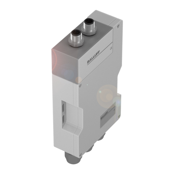
C60_1-023_819395_0508_d.p65 BIS C-6021 Montage Auswerteeinheit Montage der Die Auswerteeinheit wird mit 4 Schrauben M4 befestigt. Auswerteeinheit Head 2 Head 1 BIS C-6021 ca. 20 BIS C-6021 Öffnen der Auswerteeinheit / Anschlusspläne Öffnen der Um den Modus für die Kompatibilität einzustellen oder das EEPROM zu wechseln, ist die Auswerteeinheit Auswerteeinheit zu öffnen. - Seite 38 C60_1-023_819395_0508_d.p65 BIS C-6021 Schnittstelleninformationen / Anschlusspläne Um die Verbindungen für den I , die Betriebsspannung und den digitalen Eingang NTER herzustellen, sind die konfektionierten Kabel an der Auswerteeinheit anzuschließen. Weitere Einzelheiten zur Verdrahtung siehe folgende An den Anschlüssen Head 1 und Head 2 schließen Sie die Schreib-/Leseköpfe an. Anschluss am Die Auswerteeinheit BIS C-6021...ST8 ist für den Einsatz am Installationsfernbus vorgesehen, Fernbus oder...
- Seite 39 C60_1-023_819395_0508_d.p65 BIS C-6021...ST8 Schnittstelleninformationen / Anschlusspläne (Installationsfernbus) Anschlussplan für Um die Auswerteeinheiten BIS C-6021 in den seriellen I einzuschleifen, befinden sich NTER Auswerteeinheit am Gehäuse der Anschluss X2 als I -Ausgang und der Anschluss X3 als I NTER NTER BIS C-6021...ST8 am Eingang.
- Seite 40 C60_1-023_819395_0508_d.p65 BIS C-6021...ST9 Schnittstelleninformationen / Anschlusspläne (Fernbus) Anschlussplan für Um die Auswerteeinheiten BIS C-6021 in den seriellen INTERBUS einzuschleifen, befinden Auswerteeinheit sich am Gehäuse der Anschluss X2 als INTERBUS-Ausgang und der Anschluss X3 als BIS C-6021...ST9 am INTERBUS-Eingang. Beim Fernbus wird keine Versorgungsspannung für die Busteilnehmer Fernbus auf dem Bus mitgeführt.
- Seite 41 EG-Richtlinie 89/336/EWG (EMV-Richtlinie) und des EMV-Gesetzes entsprechen. In unserem EMV-Labor, das von der DATech für Prüfungen der elektromagnetischen Verträglichkeit akkreditiert ist, wurde der Nachweis erbracht, dass die Balluff-Produkte die EMV-Anforderungen der Fachgrundnorm EN 61000-6-4 (Emission), EN 61000-4-2/3/4/5/6 (Störfestigkeit) erfüllen.
-
Seite 42: Anhang, Ascii-Tabelle
C60_1-023_819395_0508_d.p65 BIS C-6021 Bestellinformationen Typenschlüssel BIS C-6021-023-050-03-ST_ Balluff Identifikations-System Baureihe C Schreib-/Lesesystem Hardware-Typ 6021 = Metallgehäuse, I NTER Software-Typ 023 = I NTER Adapter 050 = mit zwei Anschlüssen für externe Schreib-/Leseköpfe BIS C-3_ _ (ausgenommen BIS C-350 und -352)