Inhaltsverzeichnis
Werbung
Verfügbare Sprachen
Verfügbare Sprachen
Quicklinks
Werbung
Inhaltsverzeichnis

Verwandte Anleitungen für Dal Zotto INSERTO 700 AIR


Inhaltszusammenfassung für Dal Zotto INSERTO 700 AIR
- Seite 1 MANUALE UTENTE STUFE A PELLET PELLET STOVES USER MANUAL MANUEL UTILISATEUR POÊLES À PELLET BENUTZERHANDBUCH PELLETÖFEN MANUAL DEL USUARIO ESTUFAS DE PELLET INSERTO 700 AIR MADE ITALY design & production 004280246 REV.000...
- Seite 2 ApplicAre etichettA dAti technici...
-
Seite 3: Inhaltsverzeichnis
SICUREZZA ........................................8 ORDINARIA MANUTENZIONE ..................................10 INSTALLAZIONE ......................................11 DISTANZE MINIME ..............................................11 PREDISPOSIZIONI PER MANUTENZIONE ......................................11 DETTAGLI INSERTO 700 AIR ..................................13 INSTALLAZIONE INSERTO 700 AIR ................................14 GENERALITÀ ................................................14 INGOMBRI MINIMI ..............................................14 INSTALLAZIONE ................................................15 CONDOTTI DI RICIRCOLO ARIA ..................................17 INSTALLAZIONE ESISTENTE ..........................................17... - Seite 4 SAFETY ..........................................41 ROUTINE MAINTENANCE ....................................43 INSTALLATION ........................................ 44 MINIMUM DISTANCES ............................................44 PREPARATIONS FOR MAINTENANCE ........................................44 DETAILS OF INSERTO 700 AIR ..................................46 INSTALLATION INSERTO 700 AIR ................................. 47 GENERAL ..................................................47 MINIMUM CLEARANCE ............................................47 INSTALLATION ................................................48 FRESH AIR DUCTS ......................................50 EXISTING INSTALLATION ............................................50...
- Seite 5 SÉCURITÉ ........................................74 ENTRETIEN ORDINAIRE ....................................76 INSTALLATION ........................................ 77 DISTANCES MINIMALES ............................................77 CONSIGNES POUR L’ENTRETIEN .........................................77 DÉTAILS INSERTO 700 AIR .................................... 79 INSTALLATION INSERTO 700 AIR ................................. 80 GÉNÉRALITÉS ................................................80 DIMENSIONS MINIMALES .............................................80 INSTALLATION ................................................81 CONDUIT DE RENOUVELLEMENT DE L'AIR ..............................83 INSTALLATION EXISTANTE ............................................83...
- Seite 6 SICHERHEIT ........................................107 FACHGERECHTE WARTUNG ..................................109 INSTALLATION ......................................110 MINDESTABSTÄNDE ............................................. 110 VORBEREITUNGEN FÜR DIE WARTUNG ......................................110 DETAILS INSERTO 700 AIR ..................................112 INSTALLATION INSERTO 700 AIR ................................113 ALLGEMEINES ................................................. 113 MINDESTAUSMASSE ............................................113 INSTALLATION ................................................ 114 UMLUFTLEITUNGEN ....................................
- Seite 7 SEGURIDAD ........................................140 MANTENIMIENTO ORDINARIO ................................... 142 INSTALACIÓN ....................................... 143 DISTANCIAS MÍNIMAS ............................................143 PREDISPOSICIONES PARA MANTENIMIENTO .................................... 143 DETALLES INSERTO 700 AIR ..................................145 INSTALACIÓN INSERTO 700 AIR ................................. 146 CARACTERÍSTICAS GENERALES ........................................146 DIMENSIONES MÍNIMAS ............................................ 146 INSTALACIÓN ................................................147 CONDUCTOS DE RECICLADO DE AIRE ...............................
-
Seite 8: Italiano
Vi ringraziamo per aver scelto la nostra azienda; il nostro prodotto è un’ottima soluzione di riscaldamento nata dalla tecnologia più avanzata con una qualità di lavorazione di altissimo livello ed un design sempre attuale, al ne di farVi godere sempre in assoluta sicurezza la fantastica sensazione che il calore della amma può... - Seite 9 NON GIOCHINO CON L’APPARECCHIO. Š LA PULIZIA E LA MANUTENZIONE DESTINATA AD ESSERE EFFETTUATA DALL'UTILIZZATORE NON DEVE ESSERE EFFETTUATA DA BAMBINI SENZA SORVEGLIANZA. Š NON TOCCARE IL GENERATORE SE SI È A PIEDI NUDI E CON PARTI DEL CORPO BAGNATE O UMIDE. Š...
-
Seite 10: Ordinaria Manutenzione
ASSISTENZA TECNICA E, IN OGNI CASO, NON DISABILITARE I SISTEMI DI SICUREZZA. Š IN CASO DI INCENDIO DELLA CANNA FUMARIA MUNIRSI DI ADEGUATI SISTEMI PER SOFFOCARE LE FIAMME O RICHIEDERE L’INTERVENTO DEI VIGILI DEL FUOCO. Š QUESTO APPARECCHIO NON DEVE ESSERE UTILIZZATO COME INCENERITORE DI RIFIUTI Š... -
Seite 11: Installazione
INSTALLAZIONE GENERALITÀ Gli allacciamenti scarico fumi e idraulico devono essere eseguiti da personale quali cato che deve rilasciare documentazione di conformità di installazione secondo le norme nazionali. L'installatore deve consegnare al proprietario o a chi per esso, ai sensi della legislazione vigente, la dichiarazione di conformità dell'impianto, correlata di: 1) il libretto d' uso e manutenzione dell' apparecchio e dei componenti dell'impianto (come per esempio canali da fumo, camino, ecc.);... -
Seite 12: Scarico Fumi
In qualsiasi condizione, compresa la presenza di cappe aspiranti e/o impianti di ventilazione forzata controllata, la di erenza di pressione tra i locali di installazione del generatore e l’esterno deve risultare un valore sempre uguale o minore di 4 Pa. In presenza di apparecchi a gas di tipo B a funzionamento intermittente non destinati al riscaldamento deve essere ad essi dedicata un'apertura di aerazione e/o ventilazione. -
Seite 13: Dettagli Inserto 700 Air
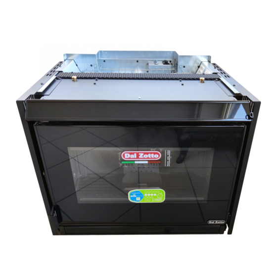
DETTAGLI INSERTO 700 AIR Uscita aria ambiente Serbatoio pellet Ingresso TA Accesso camera di combustione e Fusibile Alimentazzione 230V cassetto cenere Modulo emergenza Binario Ingresso aria comburente Uscita fumi Riarmo termostato a bulbo ITALIANO... -
Seite 14: Installazione Inserto 700 Air
INSTALLAZIONE INSERTO 700 AIR IL MONTAGGIO DEVE ESSERE ESEGUITO DA PERSONALE QUALIFICATO! GENERALITÀ L’inserto viene fornito di un basamento scorrevole in ferro che permette di installarlo in un camino preesistente. Questo basamento scorrevole permette di estrarre in modo agevolato l’inserto sia per il caricamento del pellet all’interno del serbatoio sia per eventuali manutenzioni o pulizie di ne stagione. -
Seite 15: Installazione
INSTALLAZIONE Aprire porta e utilizzando l'attizzatoio in dotazione, sbloccare il chiavistello. Togliere le 6 viti e sganciare il camino dal fondo. Fissare fondo al camino esistente. ATTENZIONE! RISPETTARE LA QUOTA 50MM PER LA CORRETTA APERTURE E CHIUSURA DELL'INSERTO! ITALIANO... - Seite 16 Fissare fondo al kit, in caso di nuova installazione (kit opzionale). Bloccare le rotaie con due cacciaviti e ssare il camino al fondo con 6 viti. Chiudere l'inserto e bloccare il chiavistello. ITALIANO...
-
Seite 17: Condotti Di Ricircolo Aria
CONDOTTI DI RICIRCOLO ARIA Per un corretto funzionamento è necessario creare un ricircolo d’aria all’interno della struttura che riveste l’inserto onde evitare eventuali surriscaldamenti dell’apparecchio. Per garantire questo è su ciente realizzare una o più aperture sia nella parte inferiore che nella parte superiore del rivestimento. Le misure da rispettare sono le seguenti: Š... -
Seite 18: Installazione Nuova
INSTALLAZIONE NUOVA ESEMPIO 1 ESEMPIO 2 A: Uscita aria di convenzione. Sezione minima 120cmq. C: Uscita aria di convenzione. Sezione minima 240cmq. B: ingresso aria dall'ambiente. Sezione minima 120cmq. D: ingresso aria dall'ambiente. Sezione minima 240cmq. Per un corretto funzionamento dell’inserto è necessario garantire uno spazio minimo laterale di 20mm e posteriore di 10mm; I rivestimenti che devono essere realizzati in materiale non in ammabile. -
Seite 19: Chiavistello Di Sicurezza
CHIAVISTELLO DI SICUREZZA Utilizzare l'attizzatoio in dotazione per eseguire l'operazione di sblocco/blocco. (Ruotare in senso rario per sbloccare, in senso antiorario per bloccare). Fori presenti su due lati per l'estrazione dell'inserto mediante attizzatoi. L’estrazione dell’inserto permette sia di caricare il pellet all’interno del serbatoio che di eseguire la manutenzione ordinaria (pulizia del condotto cenere a ne anno) o straordinarie (sostituzione di parti meccaniche in caso di rotture del prodotto). -
Seite 20: Estrazione Inserto E Caricamento Pellet
ESTRAZIONE INSERTO E CARICAMENTO PELLET L’estrazione dell’inserto permette sia di caricare il pellet all’interno del serbatoio che di eseguire delle manutenzioni ordinarie (pulizia del condotto cenere a ne anno) o straordinarie (sostituzione di parti meccaniche in caso di rotture del prodotto). Per estrarre l’inserto eseguire la seguente procedura: Aprire la porta fuoco e ruotare il chiavistello (tramite attizzatoio in dotazione) in senso orario. -
Seite 21: Accessori Opzionali Caricamento
ACCESSORI OPZIONALI CARICAMENTO KIT CARICAMENTO FRONTALE PELLET KIT CARICAMENTO PELLET SUPERIORE/LATERALE Il kit opzionale di caricamento pellet consente di caricare Il kit opzionale di caricamento pellet consente di caricare il pellet frontalmente il pellet all’interno del serbatoio senza dover all’interno del serbatoio senza estrarre l’inserto dal vano installazione procedere con l’estrazione dell’inserto (operazione che (operazione che richiederebbe lo spegnimento della macchina). -
Seite 22: Modulo Emergenza
MODULO EMERGENZA La stufa è dotata di un modulo di emergenza posta lateralmente, che consente la gestione base della stufa nel caso di guasto o malfunzionamento del palmare. Le funzioni gestibili dal modulo emergenza sono: Pulsante P1 Accensione/ spegnimento stufa L1: Led Blu spento: La stufa è... -
Seite 23: Radiocomando
RADIOCOMANDO CONFIGURAZIONE LA PROCEDURA DI CODIFICA RADIOCOMANDO: 1. Togliere l'alimentazione alla stufa. contemporaneamente no a che appare la schermata di scelta del RADIO ID. 2. Premere i tasti 3. Tramite i pulsanti selezionare la nuova RADIO ID. 4. Alimentare la stufa. Entro 10 secondi (Sulla scheda radio/emergenza il led lampeggerà) confermare l'unità scelta premendo il tasto OK sul radiocomando. -
Seite 24: Caratteristiche Radiocomando
CARATTERISTICHE RADIOCOMANDO Il radiocomando è dotato di un display LCD retro illuminato. La durata della retro illuminazione è di 5 secondi. Il display dopo un determinato tempo per ridurre il consumo delle batterie si spegne (modalità sleep). Si riaccende dopo aver premuto il tasto ON/OFF (6). ATTENZIONE! Non mettete il radiocomando a contatto diretto o indiretto con l'acqua. -
Seite 25: Display
DISPLAY SCHERMATA IN FUNZIONAMENTO STAND BY attivo Crono attivo Batteria scarica Potenza 1-5^ Tangenziale attivo Temperatura rilevata in ambiente Set temperatura ambiente impostata Visualizzazione testo Tangenziale attivo in modalità COMFORT SCHERMATA CON TERMOSTATO ESTERNO ALLACCIATO AL MORSETTO “TA” Indica il contatto del termostato supplementare esterno visualizzazione testo... -
Seite 26: Menù Generale
MENÙ GENERALE TASTO FUNZIONE TASTO FUNZIONE Scorrimento dei parametri Tasto ritorna indietro - esci Modi ca dati impostazione Tasto accensione -spegnimento Tasto accesso al menù ARIA FRONTALE EASY SETUP CRONO ABILITAZIONE PRG1 IMPOSTAZIONI DATA/ORA PRG2 LINGUA PRG3 DISPLAY PRG4 STAND BY PRIMO CARICO DELTA T GRADI... -
Seite 27: Avvertenze Generali
AVVERTENZE GENERALI Prima di procedere con l’accensione del prodotto è necessario Consigli da seguire durante le prime accensioni del prodotto: eseguire le seguenti veri che: Nelle prime ore di funzionamento possono essere generati dei fumi Š Nel caso sia previsto il collegamento ad un impianto idraulico, ed odori dovuti al normale processo di “rodaggio termico”. -
Seite 28: Funzionamento E Logica
FUNZIONAMENTO E LOGICA ACCENSIONE Una volta veri cati i punti in precedenza elencati, premere il tasto per tre secondi al ne di accendere la stufa. Per la fase di accensione sono a disposizione 15 minuti nei quali si veri ca la presenza della amma. Al raggiungimento della temperatura di controllo, la stufa interrompe la fase di accensione e passa in PREPARAZIONE. -
Seite 29: Aria Frontale
ARIA FRONTALE Questo menù permette di impostare la velocità del motore di ventilazione frontale. Range: (comfort, auto). Selezionando la modalità comfort, la velocità dell'aria frontale si porta a velocità ridotta. Per garantire l'e cenza di combustione, l'aria frontale è esclusa quando il prodotto è in potenza minima. Per impostare: OK >... -
Seite 30: Abilitazione
ABILITAZIONE Consente di abilitare/disabilitare il crono e le diverse fasce orarie della stufa. Per Impostare: OK > CRONO > ABILITAZIONE. PRG 1 4 Prg x consente di impostare l’orario di accensione e spegnimento, i giorni di utilizzo della fascia programmata e la temperatura (LOW-TA - 07 - 37 °C - HOT) e anche la potenza desiderata. - Seite 31 ESEMPIO CRONO ORARI/FASCE SOVRAPPOSTE Fascia 02:00 08:00 16:30 23:00 Set Potenza 02:00 08:00 16:30 23:00 Set Temperatura 22° 18° 02:00 08:00 16:30 23:00 start 02:00 Fascia 1 Set Potenza 3 - Set Temp 22°C stop 23:00 start 08:00 Fascia 2 Set Potenza 1 - Set Temp 18°C stop 16:30 funzionamento stufa...
-
Seite 32: Impostazioni
IMPOSTAZIONI Š DATA/ORA Š LINGUA VEDI CAPITOLO: IMPOSTAZIONI PRIMA ACCENSIONE. Š GRADI DISPLAY Il menù "DISPLAY" consente di: Š Regolare il contrasto del Display. Š Attivare/ disattivare la retroilluminazione. Š Abilitare/ disabilitare la segnalazione acustica. Š Impostare timer spegnimento retroilluminazione del Display. Š... -
Seite 33: Primo Carico
PRIMO CARICO Questa funzione permette di attivare il motoriduttore di caricamento del pellet per un funzionamento in continuo. Prima di attivare la funzione assicurarsi che la stufa sia fredda e in stato "OFF". Per Impostare: OK > IMPOSTAZIONI > PRIMO CARICO Per interrompere il caricamento in continuo è... -
Seite 34: Pulizia E Manutenzione
PER CONOSCERE IL CENTRO ASSISTENZA PIU’ VICINO CONTATTARE IL PROPRIO RIVENDITORE O CONSULTARE IL SITO: WWW.LANORDICA-EXTRAFLAME.COM PULIZIA E MANUTENZIONE ESEGUIRE LE INDICAZIONI SEMPRE NELLA MASSIMA SICUREZZA! Š ASSICURARSI CHE LA SPINA DEL CAVO DI ALIMENTAZIONE SIA STACCATA IN QUANTO IL GENERATORE POTREBBE ESSERE STATO PROGRAMMATO PER ACCENDERSI. - Seite 35 LE SUCCESSIVE IMMAGINI SONO A SCOPO ILLUSTRATIVO BRACIERE E CAMERA DI COMBUSTIONE: Rimuovere completamente braciere Š dall’apposito vano. Una volta tolto il batti amma (A) aspirare i Š residui presenti nel braciere. Š Liberare con l’apposito attizzatoio in dotazione tutti i fori presenti nel braciere. Aspirare la cenere della sede braciere e camera Š...
-
Seite 36: Manutenzione Ordinaria Eseguita Dai Tecnici Abilitati
UN BRACIERE PULITO GARANTISCE UN CORRETTO FUNZIONAMENTO! MANTENENDO IL BRACIERE E I SUOI FORI SEMPRE BEN PULITI DA EVENTUALI RESIDUI DI COMBUSTIONE, SI GARANTISCE AL GENERATORE UN’OTTIMA COMBUSTIONE NEL TEMPO, EVITANDO EVENTUALI MALFUNZIONAMENTI CHE POTREBBERO RICHIEDERE L’INTERVENTO DEL TECNICO. È POSSIBILE UTILIZZARE LA FUNZIONE NEL MENU UTENTE "EASY SETUP" PER ADEGUARE LA COMBUSTIONE IN BASE ALLE ESIGENZE DESCRITTE. -
Seite 37: Manutenzione Ordinaria
MANUTENZIONE ORDINARIA LE IMMAGINI SONO A SCOPO ILLUSTRATIVO. Motore fumi (smontaggio e pulizia e condotto fumi e "T"). Guarnizioni, ispezioni, porta (sostituire dove previsto), braciere e scambiatore Camera di combustione & scambiatore (pulizia totale) compreso pulizia condotto candeletta Serbatoio (svuotamento completo e pulizia). Veri ca tubo di aspirazione aria. -
Seite 38: Visualizzazioni
VISUALIZZAZIONI DISPLAY MOTIVAZIONE Generatore spento START E' in corso la fase di START CARICA PELLET E' in corso il carico continuo del pellet durante lo stato di accensione ACCENSIONE E' in corso la fase dedicata all'innesco della amma PREPARAZIONE E' in corso la fase di stabilizzazione della amma LAVORO Il generatore è... -
Seite 39: Condizioni Di Garanzia
CONDIZIONI DI GARANZIA I prodotti DAL ZOTTO marchio commerciale di LA NORDICA S.p.A. sono garantiti, nell’ambito della comunità europea, per un periodo di 24 mesi dalla data di acquisto. L’acquisto deve essere provato da un documento scalmente valido rilasciato dal rivenditore (scontrino scale, fattura o bolla di trasporto) che identi chi il prodotto acquistato e la data di acquisto e/o consegna dello stesso. -
Seite 40: Smaltimento
Qualora il Prodotto venisse riparato presso uno dei Centri Assistenza Tecnica Autorizzati indicati dalla DAL ZOTTO e nel caso di sostituzione del prodotto, il trasporto sarà gratuito. Nei casi in cui il tecnico fosse in grado di riparare il prodotto presso il domicilio dell’utente, è lo stesso si ri utasse, il trasporto in laboratorio e la riconsegna saranno invece a suo carico. -
Seite 41: English
We thank you for having chosen our company; our product is a great heating solution developed from the most advanced technology with top quality machining and modern design, aimed at making you enjoy the fantastic sensation that the heat of a ame gives, in complete safety. WARNINGS This instructions manual is an integral part of the product: make sure that it always accompanies the appliance, even if transferred to another owner... - Seite 42 CHILDREN WITH REDUCED PHYSICAL, SENSORY AND MENTAL CAPACITIES OR WHO ARE UNSKILLED PERSONS, UNLESS THEY ARE SUPERVISED AND TRAINED REGARDING USE OF THE APPLIANCE BY A PERSON RESPONSIBLE FOR THEIR SAFETY. Š THE CLEANING AND MAINTENANCE REQUIRED BY THE USER MUST NOT BE PERFORMED BY CHILDREN WITHOUT SUPERVISION.
-
Seite 43: Routine Maintenance
SYSTEMS. Š IN THE EVENT THE FLUE CATCHES FIRE, USE SUITABLE SYSTEMS FOR SUFFOCATING THE FLAMES OR REQUEST HELP FROM THE FIRE BRIGADE. Š THIS APPLIANCE MUST NOT BE USED TO BURN WASTE Š DO NOT USE ANY FLAMMABLE LIQUIDS FOR IGNITION Š... -
Seite 44: Installation
INSTALLATION GENERAL The ue gas exhaust and hydraulic connections must be carried out by quali ed personnel who must issue installation conformity documentation compliant with national standards. The installer must provide the owner or person acting for him, according to the legislation in force, with the declaration of conformity, supplied with: 1) the use and maintenance manual of the appliance and of the system components (such as for example, the smoke ducts, chimney, etc.);... -
Seite 45: Flue Gas Exhaust
In the presence of type B gas appliances with intermittent operation not intended for heating, they must have their own aeration and/or ventilation opening. The air inlets must meet the following requirements: Š they must be protected with grids, metal mesh, etc., but without reducing the net useful section; Š... -
Seite 46: Details Of Inserto 700 Air
DETAILS OF INSERTO 700 AIR Ambient air outlet Pellet hopper TA inlet Access to combustion chamber Fuse 230V power supply and ash drawer Emergency module Rail Combustion air inlet Fumes outlet Bulb thermostat rearm ENGLISH... -
Seite 47: Installation Inserto 700 Air
INSTALLATION INSERTO 700 AIR ASSEMBLY MUST BE CARRIED OUT BY QUALIFIED PERSONNEL! GENERAL The insert is supplied with a sliding base in iron that allows it to be installed in a pre-existing chimney. This sliding base allows the insert to be removed easily to load the pellets inside the hopper and for any maintenance or cleaning at the end of the season. -
Seite 48: Installation
INSTALLATION Open the door and release the latch using the poker supplied. Remove the 6 screws and remove the ue pipe from the base. Fix the base to the existing ue pipe. ATTENTION! RESPECT THE 50MM HEIGHT FOR OPENING AND CLOSING THE INSERT CORRECTLY! ENGLISH... - Seite 49 Fix the base to the kit if it is a new installation (optional kit). Block the rails with two screwdrivers and secure the ue pipe to the base with 6 screws. Close the insert and block the latch. ENGLISH...
-
Seite 50: Fresh Air Ducts
FRESH AIR DUCTS For correct operation, air must be allowed to recirculate inside the structure that covers the insert in order to prevent the appliance from overheating. To guarantee this, just realise one or more openings in the lower and upper part of the covering. The following measurements must be respected: Š... -
Seite 51: New Installation
NEW INSTALLATION EXAMPLE 1 EXAMPLE 2 A: Air convection outlet. Minimum section 120cm C: Air convection outlet. Minimum section 240cm B: air inlet from room. Minimum section 120cm D: air inlet from room. Minimum section 240cm For the insert to operate correctly, a minimum side of 20 mm and rear space of 10 mm must be guaranteed; the coatings must be made of non- ammable material. -
Seite 52: Safety Latch
SAFETY LATCH Use the poker supplied to perform the release/block operation. (Turn clockwise to release and anti-clockwise to block). Holes present on two sides for the extraction of the insert via pokers. Extraction of the insert allows both the pellets to be loaded inside the hopper and routine maintenance (cleaning the ash pipe at year end) or unscheduled maintenance (replacement of mechanical parts if the product should break) to be performed. -
Seite 53: Extraction Of Insert And Pellet Loading
EXTRACTION OF INSERT AND PELLET LOADING Extraction of the insert allows both the pellets to be loaded inside the hopper and routine maintenance (cleaning the ash pipe at year end) or unscheduled maintenance (replacement of mechanical parts if the product should break) to be performed. To extract the insert, follow the procedure below: Open the re door and turn the latch clockwise (using the poker supplied). -
Seite 54: Optional Loading Accessories
OPTIONAL LOADING ACCESSORIES FRONT PELLET LOADING KIT UPPER/SIDE PELLET LOADING KIT The optional pellet loading kit allows to load the pellets into the The optional pellet loading kit allows to load the pellets into the hopper from the front without having to remove the insert (which hopper without removing the insert from the installation opening would require the machine to be switched o ). -
Seite 55: Emergency Module
EMERGENCY MODULE The stove is tted with an emergency module located at the side, allowing the basic operation of the stove in the event the handheld remote is damaged or malfunctions. The functions that can be managed from the emergency module are: Key P1 Stove ignition/switch-o L1: Blue LED o :... -
Seite 56: Radio Control
RADIO CONTROL CONFIGURATION RADIO CONTROL CODING PROCEDURE: 1. Disconnect the power supply to the stove. at the same time until the screen to choose RADIO ID appears. 2. Press the keys 3. Using keys select the new RADIO ID. 4. Power the stove. Con rm the selected unit within 10 seconds (the LED will ash on the radio/emergency card) by pressing the OK key on the remote control. -
Seite 57: Radio Control Features
RADIO CONTROL FEATURES The radio control is tted with an LCD backlit display. The display remains lit for 5 seconds. After a certain period of time, in order to minimise battery consumption, the display turns o (sleep mode). It turns on again after pressing the ON/OFF key (6). CAUTION! Do not place the radio control device in direct or indirect contact with water. -
Seite 58: Display
DISPLAY SCREEN IN OPERATION STAND BY active Chrono active Battery low Power 1-5^ Hour Tangential fan active Temperature detected in room Set ambient temperature Display text Tangential fan active in COMFORT mode SCREEN WITH EXTERNAL THERMOSTAT CONNECTED TO THE TERMINAL “TA” Time Indicates contact of the external additional... -
Seite 59: General Menu
GENERAL MENU FUNCTION FUNCTION Scroll parameters Back - exit key Modify settings Ignition - switch-o key Access menu key FRONT AIR EASY SETUP CHRONO ENABLING PRG1 SETTINGS DATE/TIME PRG2 LANGUAGE PRG3 DISPLAY PRG4 STAND BY FIRST LOAD DELTA T DEGREES RESET DEPRESSURE NOTICE... -
Seite 60: General Warnings
GENERAL WARNINGS Advice to follow for the rst start-ups of the product: Before turning on the product, it is necessary to perform the During the rst hours of operation, there may be some smoke or following checks: odours, but they are due to the normal “thermal break-in” process. Š... -
Seite 61: Operation And Logic
OPERATION AND LOGIC IGNITION Once the previously listed points have been checked, press key for three seconds to ignite the stove. During ignition, the stove will check for a ame for a period of 15 minutes. Once the control temperature has been reached, the stove interrupts the ignition phase and switches to PREPARATION. -
Seite 62: Front Air
FRONT AIR This menu allows the front ventilation motor speed to be set. Range: (comfort, auto). If comfort mode is selected, the front air speed is reduced. To guarantee e cient combustion, front air is excluded when the appliance is running at minimum power. To set: OK >... -
Seite 63: Enabling
ENABLING Allows the chrono and the di erent stove time slots to be enabled/disabled. To set: OK > CHRONO > ABILITAZIONE. PRG 1 4 Prg x allows you to set the on/o time, the days of use of the scheduled time slot and the temperature (LOW-TA - 07 - 37 °C - HOT), plus the required power. - Seite 64 EXAMPLE OF CHRONO OVERLAPPING TIMES/SLOTS Time slot 02:00 08:00 16:30 23:00 Set Power 02:00 08:00 16:30 23:00 Set Temperature 22° 18° 02:00 08:00 16:30 23:00 start 02:00 Time slot 1 Set Power 3 - Set Temp 22°C stop 23:00 start 08:00 Time slot 2 Set Power 1 - Set Temp 18°C stop 16:30...
-
Seite 65: Settings
SETTINGS Š DATE/TIME Š LANGUAGE SEE CHAPTER: COMMISSIONING SETTINGS. Š DEGREES DISPLAY The "DISPLAY" menu allows: Š Regulation of DISPLAY contrast Š Activation/Deactivation of backlight. Š Enabling/disabling of acoustic signal. Š Setting of the timer to turn o the Display backlight. Š... -
Seite 66: First Load
FIRST LOAD This function allows you to activate the gearmotor for loading pellets continuously. Before starting the function, make sure the stove is cold and “OFF”. To set: OK > SETTINGS > FIRST LOAD To stop continuous loading, just press and hold key 6 for 2 seconds. Quick access: Before starting the function, make sure the stove is cold and “OFF”. -
Seite 67: Cleaning And Maintenance
TO FIND OUT WHERE YOUR NEAREST SERVICE CENTRE IS, CONTACT YOUR DEALER OR VISIT THE WEBSITE: WWW.LANORDICA-EXTRAFLAME.COM CLEANING AND MAINTENANCE ALWAYS FOLLOW THE INSTRUCTIONS IN COMPLETE SAFETY! Š MAKE SURE THAT THE POWER CORD IS UNPLUGGED BECAUSE THE GENERATOR MAY HAVE BEEN PROGRAMMED TO SWITCH ON. Š... - Seite 68 THE FOLLOWING IMAGES ARE FOR ILLUSTRATION PURPOSES BURN POT AND COMBUSTION CHAMBER: Remove the burn pot completely from the Š relevant compartment. Once the ame guard (A) has been removed, Š vacuum the residue in the burn pot. Š Unblock all the holes in the burn pot using the supplied poker.
-
Seite 69: Routine Maintenance Performed By Qualified Technicians
A CLEAN BURN POT GUARANTEES CORRECT OPERATION! BY KEEPING THE BURN POT AND ITS HOLES CONSTANTLY CLEAN AND FREE OF COMBUSTION RESIDUE, EXCELLENT COMBUSTION IS GUARANTEED OVER TIME, THUS PREVENTING ANY GENERATOR MALFUNCTIONS THAT MAY REQUIRE TECHNICAL ASSISTANCE. THE "EASY SETUP" FUNCTION IN THE USER MENU CAN BE USED TO ADAPT COMBUSTION ON THE BASIS OF THE NEEDS DESCRIBED. -
Seite 70: Routine Maintenance
ROUTINE MAINTENANCE THE IMAGES ARE FOR ILLUSTRATIVE PURPOSES. Fumes motor (dismantling and cleaning, ue pipe and "T” tting). Gaskets, inspections, door (replace if necessary), burn pot and heat exchanger Combustion chamber and heat exchanger (full cleaning) including ignition plug pipe Hopper (complete emptying and cleaning). -
Seite 71: Displays
DISPLAYS UPDATE REASON Generator o START The START phase is in progress PELLET LOADING Continuous pellet feeding is in progress during the ignition state IGNITION The phase dedicated to ignition is in progress PREPARATION The ame stabilisation phase is in progress WORK The generator has reached operating capacity and is working on user settings MODULATION... -
Seite 72: Guarantee Terms
DAL ZOTTO (LA NORDICA S.p.A. brand) cannot be held liable for injury or damage which may - either directly or indirectly - be caused to persons, animals and property ensuing from failure to observe all the instructions provided in the relevant instruction manual and the warnings regarding installation, use and maintenance of the product, that can also be downloaded on the website. -
Seite 73: Disposal
After the 24 months of the guarantee have elapsed any repair intervention cost will be completely borne by the consumer. In the case of disputes the only competent court is that of the DAL ZOTTO registered o ce - (Vicenza - Italy) ADDITIONAL WARNINGS Š... -
Seite 74: Français
Nous vous remercions d'avoir choisi notre produit. Notre appareil est une solution de chau age optimale née de la technologie la plus avancée avec une qualité de fabrication de très haut niveau et un design toujours actuel, pour vous faire pro ter – en toute sécurité – de la merveilleuse sensation que procure la chaleur de la amme. - Seite 75 L’APPAREIL ET EN AVOIR COMPRIS LES DANGERS INHÉRENTS.L'UTILISATION DU GÉNÉRATEUR PAR DES PERSONNES Y COMPRIS LES ENFANTS AYANT DES CAPACITÉS PHYSIQUES, SENSORIELLES ET MENTALES RÉDUITES, OU DES PERSONNES INEXPÉRIMENTÉES EST INTERDITE À MOINS QU'UNE PERSONNE RESPONSABLE DE LEUR SÉCURITÉ NE LES SURVEILLE ET LES INSTRUISE. Š...
-
Seite 76: Entretien Ordinaire
GÉNÉRATEUR. SI CELA SE VÉRIFIE, CONTACTER LE SERVICE D’ASSISTANCE TECHNIQUE ET SURTOUT NE PAS DÉSACTIVER LES SYSTÈMES DE SÉCURITÉ. Š EN CAS D'INCENDIE DU CONDUIT DE FUMÉE, SE MUNIR D'EXTINCTEURS POUR ÉTOUFFER LES FLAMMES OU APPELER LES POMPIERS. Š CET APPAREIL NE DOIT PAS ÊTRE UTILISÉ COMME INCINÉRATEUR DE DÉCHETS. -
Seite 77: Installation
INSTALLATION GÉNÉRALITÉS Les branchements évacuation des fumées et hydraulique doivent être e ectués par un personnel quali é qui doit délivrer une attestation de conformité d'installation selon les normes nationales. L'installateur doit remettre au propriétaire ou à la personne qui le représente, conformément à la loi en vigueur, la déclaration de conformité... -
Seite 78: Évacuation Des Fumées
En présence d'appareils à gaz de type B à fonctionnement intermittent, non destinés au chau age, il faut e ectuer une ouverture d'aération et/ou de ventilation. Les prises d'air doivent répondre aux exigences suivantes : Š être protégées par des grilles, grillages métalliques, etc., sans en réduire la section utile nette ; Š... -
Seite 79: Détails Inserto 700 Air
DÉTAILS INSERTO 700 AIR Sortie air ambiant Réservoir à pellet Entrée TA Accès chambre de combustion et Fusible Alimentation 230V tiroir à cendres Module urgence Rail Entrée air comburant Sortie des fumées Réarmement thermostat à bulbe FRANCAIS... -
Seite 80: Installation Inserto 700 Air
INSTALLATION INSERTO 700 AIR LE MONTAGE DOIT ÊTRE EFFECTUÉ PAR UN PERSONNEL QUALIFIÉ ! GÉNÉRALITÉS L'insert a une base coulissante en fer qui facilite l'installation à l'intérieur de la cheminée existante. Cette base coulissante permet d'extraire facilement l'insert tant pour remplir le réservoir de pellet ou pour les opérations d'entretien ou le... -
Seite 81: Installation
INSTALLATION Ouvrir la porte et, en utilisant le tisonnier fourni, débloquer le verrou. Enlever les 6 vis et séparer la cheminée de la partie inférieure. Fixer la partie inférieure à la cheminée existante. ATTENTION ! RESPECTER LA VALEUR DE 50MM POUR L’OUVERTURE ET FERMETURE CORRECTES DE L’INSERT ! FRANCAIS... - Seite 82 Fixer la partie inférieure au kit en cas de nouvelle installation (kit en option). Bloquer les rails avec deux tournevis et xer la cheminée à la partie inférieure avec 6 vis. Fermer l'insert et bloquer le verrou. FRANCAIS...
-
Seite 83: Conduit De Renouvellement De L'air
CONDUIT DE RENOUVELLEMENT DE L'AIR Pour un fonctionnement correct il faut créer un circuit de renouvellement de l'air à l'intérieur de la structure qui couvre l'insert a n d'éviter les surchau es. Pour ce faire, il su t de réaliser une ou plusieurs ouvertures sur la partie inférieure et la partie supérieure du revêtement. Les mesures à... -
Seite 84: Nouvelle Installation
NOUVELLE INSTALLATION EXEMPLE 1 EXEMPLE 2 A : Sortie air de convection. Section minimale 120cm². C : Sortie air de convection. Section minimale 240cm². B : entrée air de la pièce. Section minimale 120cm². D : entrée air de la pièce. Section minimale 240cm². Pour un fonctionnement correct de l’insert, il est nécessaire de garantir un espace minimal latéral de 20mm et arrière de 10mm ;... -
Seite 85: Verrou De Sécurité
VERROU DE SÉCURITÉ Utiliser le tisonnier fourni pour réaliser l'opération de déblocage/blocage. (Tourner dans le sens des aiguilles d’une montre pour débloquer, dans le sens inverse des aiguilles d’une montre pour bloquer). Trous présents des deux côtés pour l'extraction de l'insert avec les tisonniers. L'extraction de l'insert permet de charger le pellet à... -
Seite 86: Extraction De L'insert Et Chargement Du Pellet
EXTRACTION DE L’INSERT ET CHARGEMENT DU PELLET L'extraction de l'insert permet de charger le pellet à l'intérieur du réservoir mais aussi d'e ectuer des entretiens courants (nettoyage du conduit des cendres en n d'année) ou exceptionnel (remplacement de pièces mécaniques en cas de ruptures du produit). Pour extraire l’insert, suivre la procédure suivante : Ouvrir la porte et tourner le verrou (à... -
Seite 87: Accessoires De Chargement En Option
ACCESSOIRES DE CHARGEMENT EN OPTION KIT DE CHARGEMENT FRONTAL DU PELLET KIT DE CHARGEMENT DE PELLET SUPÉRIEUR/LATÉRAL Le kit de chargement du pellet en option permet de charger le pellet par Le kit de chargement du pellet en option permet de charger le pellet à l'avant, à... -
Seite 88: Module Urgence
MODULE URGENCE Le poêle est équipé d'un module d’urgence placé latéralement, qui permet la gestion de base du poêle en cas de panne ou de dysfonctionnement de la télécommande. Les fonctions pouvant être gérées par le module d'urgence sont : Bouton P1 Allumage/ extinction poêle L1 : Voyant Bleu éteint :... -
Seite 89: Télécommande
TÉLÉCOMMANDE CONFIGURATION LA PROCÉDURE DE PROGRAMMATION DE LA TÉLÉCOMMANDE : 1. Couper l'alimentation du poêle. à l'apparition de la page-écran de sélection de la RADIO ID. 2. Appuyer simultanément sur les touches 3. Par le biais des touches sélectionner la nouvelle RADIO ID. 4. -
Seite 90: Caractéristiques De La Télécommande
CARACTÉRISTIQUES DE LA TÉLÉCOMMANDE La télécommande est dotée d'un a cheur LCD rétroéclairé. Le rétroéclairage dure 5 secondes. L'a cheur s'éteint au bout d'un certain temps pour réduire la consommation des piles (modalité sleep). Il se rallume après avoir appuyé sur la touche ON/OFF (6). ATTENTION ! Ne pas mettre la télécommande en contact direct ou indirect avec de l'eau. -
Seite 91: Ecran
ECRAN AFFICHEUR EN COURS DE FONCTIONNEMENT STAND BY actif Chrono actif Batterie déchargée Puissance 1-5^ Heure Tangentiel actif Température relevée dans la pièce Set température ambiante dé nie A chage texte Tangentiel actif en mode COMFORT PAGE ÉCRAN AVEC THERMOSTAT EXTERNE BRANCHE A LA BORNE TA Heure Indique le contact du thermostat externe... -
Seite 92: Menu Général
MENU GÉNÉRAL TOUCHE FONCTION TOUCHE FONCTION Dé lement des paramètres Touche précédent - quitter Modi cation des données de con guration Touche allumage - arrêt Touche d'accès au menu AIR AMBIANCE EASY SETUP CHRONO HABILITATION PRG1 RÉGLAGES DATE/HEURE PRG2 LANGUE PRG3 ÉCRAN PRG4... -
Seite 93: Mises En Garde Générales
MISES EN GARDE GÉNÉRALES Conseils à suivre durant les premières mises en marche du produit : Avant de procéder à l’allumage du produit, il faut e ectuer les Au cours des premières heures de fonctionnement, des fumées et contrôles suivants : des odeurs peuvent être émises ;... -
Seite 94: Fonctionnement Et Logique
FONCTIONNEMENT ET LOGIQUE ALLUMAGE Après avoir véri é les points précédemment énumérés, appuyer sur la touche pendant trois secondes pour allumer le poêle. Pour la phase d'allumage, 15 minutes sont à disposition pour véri er la présence de la amme. Quand la température de contrôle est atteinte, le poêle interrompt la phase d'allumage et passe en DEMARRAGE. -
Seite 95: Air Ambiance
AIR AMBIANCE Ce menu permet de dé nir la vitesse du moteur de ventilation frontale. Modes : (comfort, auto). En sélectionnant le mode « comfort », la vitesse de l’air ambiance se met à une vitesse réduite. Pour garantir l’e cacité de combustion, l’air ambiance est exclu quand le produit est à la puissance minimale. Pour le réglage : OK >... -
Seite 96: Habilitation
HABILITATION Permet d'activer/désactiver le chrono et les di érents créneaux horaires du poêle. Pour le réglage : OK > CHRONO > HABILITATION. PRG. 1 4 Prg x permet de dé nir l’heure d’allumage et d’arrêt, les jours d’utilisation du créneau horaire programmé et la température (LOW-TA - 07 - 37 °C - HOT) et aussi la puissance souhaitée. - Seite 97 EXEMPLE CHRONO HORAIRES/CRÉNEAUX SUPERPOSÉS Créneau horaire 02:00 08:00 16:30 23:00 Set Puissance 02:00 08:00 16:30 23:00 Set Température 22° 18° 02:00 08:00 16:30 23:00 start 02:00 Créneau horaire 1 Set Puissance 3 - Set Temp 22°C stop 23:00 start 08:00 Créneau horaire 2 Set Puissance 1 - Set Temp 18°C stop 16:30...
-
Seite 98: Réglages
RÉGLAGES Š DATE/HEURE Š LANGUE VOIR CHAPITRE : CONFIGURATIONS PREMIER ALLUMAGE. Š DEGREES AFFICHEUR Le menu « AFFICHEUR » permet de : Š Régler le contraste de l'ECRAN Š Activer/désactiver le rétroéclairage. Š Activer/désactiver la signalisation acoustique. Š Régler le minuteur de l'extintion du rétroéclairage de l'Ecran. Š... -
Seite 99: Charge Initiale
CHARGE INITIALE Cette fonction permet d'activer le motoréducteur de chargement du pellet pour un fonctionnement en continu. Avant d'activer la fonction, véri er que le poêle est froid et sur « OFF ». Pour le réglage : OK > RÉGLAGES > CHARGE INITIALE Pour interrompre le chargement en continu, il su t d'appuyer sur la touche 6 pendant 2". -
Seite 100: Nettoyage Et Entretien
POUR CONNAITRE LE CENTRE D'ASSISTANCE LE PLUS PROCHE, CONTACTER LE REVENDEUR OU CONSULTER LE SITE : WWW.LANORDICA-EXTRAFLAME.COM NETTOYAGE ET ENTRETIEN TOUJOURS SUIVRE LES INDICATIONS AVEC LE MAXIMUM DE SÉCURITÉ ! Š S'ASSURER QUE LA FICHE DU CORDON D'ALIMENTATION EST ENLEVÉE CAR LE GÉNÉRATEUR POURRAIT AVOIR ÉTÉ PROGRAMMÉ POUR S'ALLUMER. -
Seite 101: Tiroir A Cendres
LES IMAGES suivantes SONT DONNEES A TITRE D'EXEMPLE BRASIER ET CHAMBRE DE COMBUSTION : Enlever complètement le brasier de son Š logement. Après avoir enlevé la plaque foyère (A), aspirer Š les résidus présents dans le brasier. Š Libérer tous les trous du brasier avec le tisonnier fourni. -
Seite 102: Entretien Courant À Effectuer Par Les Techniciens Autorisés
UN BRASIER PROPRE GARANTIT UN FONCTIONNEMENT CORRECT ! LE FAIT DE MAINTENIR LE BRASIER ET SES ORIFICES TOUJOURS BIEN PROPRES, SANS RÉSIDUS DE COMBUSTION, GARANTIT AU GÉNÉRATEUR UNE BONNE COMBUSTION AU FIL DU TEMPS, ET ÉVITE LES ÉVENTUELS DYSFONCTIONNEMENTS QUI POURRAIENT EXIGER L'INTERVENTION DU TECHNICIEN. - Seite 103 ENTRETIEN ORDINAIRE LES IMAGES SONT DONNEES A TITRE D'EXEMPLE. Moteur des fumées (démontage et nettoyage du conduit de fumée et des raccords en « T »). Joints, trappes d'inspection, porte (remplacer le cas échéant), brasier et échangeur Chambre de combustion et échangeur (nettoyage total) y compris le nettoyage du culot de la bougie Réservoir (vidage complet et nettoyage).
-
Seite 104: Affichages
AFFICHAGES ECRAN CAUSE Générateur éteint START La phase de START est en cours PRECHARGE PELLET Le chargement continu du pellet est en cours durant la phase d'allumage ALLUMAGE La phase dédiée à l'allumage de la amme est en cours DEMARRAGE La phase dédiée à... -
Seite 105: Conditions De Garantie
CONDITIONS DE GARANTIE Les produits DAL ZOTTO, marque commerciale de LA NORDICA S.p.A. sont garantis, conformément aux directives de la communauté européenne, pour une période de 24 mois à compter de la date d'achat. Un document scal valide qui prouve l'achat, délivré par le vendeur (ticket de caisse, facture ou bon de transport), identi ant le produit acheté... -
Seite 106: Élimination
Si le produit est réparé auprès d'un des Centres d'Assistance Technique Agréés indiqués par DAL ZOTTO et en cas de remplacement du produit, le transport sera gratuit. Si le technicien est en mesure de réparer le produit au domicile de l'utilisateur et que celui-ci refuse, le transport au laboratoire et la livraison de retour seront à... -
Seite 107: Deutsch
Wir danken Ihnen dafür, dass Sie sich für unsere Firma entschieden haben; unser Produkt ist eine ideale Heizlösung, die auf der neuesten Technologie basiert, sehr hochwertig verarbeitet ist und ein zeitloses Design aufweist, damit Sie stets in aller Sicherheit das fantastische Gefühl genießen können, das Ihnen die Wärme der Flamme geben kann. - Seite 108 WERDEN, SOFERN SIE ÜBERWACHT WERDEN ODER ANWEISUNGEN BEZÜGLICH DES SICHEREN GEBRAUCHS DES GERÄTS ERHIELTEN UND SICH DER DAMIT VERBUNDENEN GEFAHREN BEWUSST SIND. Š DER GEBRAUCH DIESES WÄRMERZEUGERS DURCH PERSONEN KINDER EINGESCHLOSSEN MIT EINGESCHRÄNKTEN PHYSISCHEN, SENSORISCHEN ODER PSYCHISCHEN FÄHIGKEITEN IST VERBOTEN UNTERSAGT, ES SEI DENN, SIE WERDEN BEIM GEBRAUCH DES GERÄTES ZUR IHRER EIGENEN SICHERHEIT VON EINER VERANTWORTLICHEN PERSON ÜBERWACHT UND ANGEWIESEN.
-
Seite 109: Fachgerechte Wartung
ABSCHALTEN. WENN DIES EINTRITT, WENDEN SIE SICH AN DEN TECHNISCHEN KUNDENDIENST ODER IHREN FACHHÄNDLER. UND SETZEN SIE KEINESFALLS DIE SICHERHEITSVORRICHTUNGEN AUSSER KRAFT! Š IM FALL EINES SCHORNSTEINBRANDES RUFEN SIE SOFORT DIE FEUERWEHR UND IHREN ZUSTÄNDIGEN BEZIRKSSCHORNSTEIN FEGERMEISTER. VERHINDERN SIE, WENN MÖGLICH, BIS ZUM EINTREFFEN DER FEUERWEHR EIN AUSBREITEN DES BRANDES AUF AN DEN SCHORNSTEIN ANGRENZENDE BRENNBARE BAUTEILE WIE BEISPIELSWEISE MOBILAR, HOLZBAUTEILE WIE HOLZBALKEN, HOLZDECKE ODER BODEN SOWIE TEPPICHE, KABEL ETC.ETC. -
Seite 110: Installation
INSTALLATION ALLGEMEINES Die Anschlüsse für den Rauchabzug und Wasser müssen von Fachpersonal ausgeführt werden, das entsprechend den nationalen Bestimmungen eine Dokumentation zur Konformität der Installation ausstellen muss. Der Installateur muss dem Eigentümer oder dessen Vertreter gemäß den geltenden gesetzlichen Vorschriften die Konformitätserklärung der Anlage aushändigen, der beizufügen sind: 1) die Betriebs- und Wartungsanleitung des Geräts und der Bauteile der Anlage (wie zum Beispiel Rauchgaskanäle, Schornstein usw.);... -
Seite 111: Beispiele Für Den Richtigen Schornsteinanschluss
Wenn Gas-Geräte vom Typ B mit Aussetzbetrieb vorhanden sind, die nicht der Heizung dienen, muss für diese eine eigene Belüftungsö nung vorhanden sein. Die Luftzuleitungen müssen folgende Anforderungen erfüllen: Š sie müssen durch Roste, Metallgitter usw. geschützt sein, ohne dass dadurch der freie Lüftungsquerschnitt reduziert wird; Š... -
Seite 112: Details Inserto 700 Air
DETAILS INSERTO 700 AIR Auslass Raumluft Pelletbehälter Eingang ext. Thermostat Zugang Brennkammer und Sicherung 230V Versorgung Aschekasten Modul für Notfall Schiene Einlass Verbrennungsluft Rauchgasauslass Rückstellungen Kolbenthermostat DEUTSCH... -
Seite 113: Installation Inserto 700 Air
INSTALLATION INSERTO 700 AIR DIE MONTAGE MUSS VON QUALIFIZIERTEM PERSONAL AUSGEFÜHRT WERDEN! ALLGEMEINES Der Einsatz wird mit einem verschiebbaren Unterbau aus Eisen geliefert, der es erlaubt, ihn in einem bereits bestehenden Kamin zu installieren. Der verschiebbare Unterbau ermöglicht es, das der Einsatz sowohl zum Einfüllen der Pellets als auch für Wartung und Reinigung am... -
Seite 114: Installation
INSTALLATION Die Türe ö nen und unter Verwendung des Schürhakens den Riegel entsperren. Die 6 Schrauben entfernen und den Kamin vom Boden aushängen. Den Boden am bestehenden Kamin befestigen. ACHTUNG! DAS MASS VON 50MM FÜR DIE KORREKTE ÖFFNUNG UND SCHLIESSUNG DES EINSATZES BEACHTEN! DEUTSCH... - Seite 115 Den Boden an das Kit im Falle einer neuen Installation befestigen (optionales Kit). Die Schienen mit zwei Schraubenziehern blockieren und den Kamin am Boden mit 6 Schrauben befestigen. Den Einsatz schließen und den Riegel blockieren. DEUTSCH...
-
Seite 116: Umluftleitungen
UMLUFTLEITUNGEN Für einen korrekten Betrieb ist es notwendig, eine Luftzirkulation im Inneren der Struktur des Einsatz zu scha en, um eventuelle Überhitzungen des Geräts zu vermeiden. Um dies zu gewährleisten, ist es ausreichend, eine oder mehr Ö nungen sowohl im unteren als auch im oberen Teil der Verkleidung zu erstellen. -
Seite 117: Neue Installation
NEUE INSTALLATION BEISPIEL 1 BEISPIEL 2 A: Ausgang Konvektionsluft. Mindestquerschnitt 120cm². C: Ausgang Konvektionsluft. Mindestquerschnitt 240cm². B: Eingang Raumluft. Mindestquerschnitt 120cm². D: Eingang Raumluft. Mindestquerschnitt 240cm². Für eine korrekte Funktionsweise des Einsatzes ist es erforderlich, einen seitlichen von 20mm und hinteren Mindestraum von 10mm dargestellt zu gewährleisten;... -
Seite 118: Sicherheitsriegel
SICHERHEITSRIEGEL Den Schürhaken aus der Ausstattung verwenden, um den Vorgang der Entriegelung/Verriegelung auszuführen. (Im Uhrzeigersinn drehen, um zu entriegeln, im Gegenuhrzeigersinn, um zu verriegeln). Auf beiden Seiten vorhandene Bohrungen zum Auszug des Einsatzes mit Hilfe von Schürhaken Der Auszug des Einsatzes erlaubt sowohl das Laden der Pellets in das Innere des Tanks als auch die Ausführung der ordentlichen Wartung (Reinigung des Aschenrohrs am Jahresende) oder der außerordentlichen Wartung (Austausch von mechanischen Teilen im Fall von Bruch des Produkts). -
Seite 119: Auszug Des Einsatzes Und Laden Der Pellets
AUSZUG DES EINSATZES UND LADEN DER PELLETS Der Auszug des Einsatzes erlaubt sowohl das Laden der Pellets in das Innere des Tanks als auch die Ausführung von ordentlichen Wartungen (Reinigung des Aschenrohrs am Jahresende) oder von außerordentlichen Wartungen (Austausch von mechanischen Teilen im Fall von Bruch des Produkts). -
Seite 120: Optionales Zubehör Zur Ladung
OPTIONALES ZUBEHÖR ZUR LADUNG KIT ZUM FRONTALEN LADEN DER PELLETS KIT ZUM OBEREN/SEITLICHEN LADEN DER PELLETS Das optionale Kit zum Laden der Pellets erlaubt, sie in das Innere des Das optionale Kit zum Laden der Pellets erlaubt, sie in das Innere des Tanks zu Tanks zu laden, ohne den Einsatz herausnehmen zu müssen (Vorgang, laden, ohne den Einsatz aus dem Installationsfach herauszunehmen (Vorgang, der das Abschalten des Geräts erfordern würde). -
Seite 121: Modul Für Notfall
MODUL FÜR NOTFALL Der Ofen ist mit einem Not-Modul, das sich seitlich be ndet, ausgestattet, und das die Grundverwaltung des Ofens im Fall von Defekt oder Fehlfunktion des Handbediengeräts erlaubt. Die Funktionen, die durch das Not-Modul verwaltet werden können, sind: Taste P1 Zündung/ Abschaltung des Ofens L1: Blaue Led aus:... -
Seite 122: Funksteuerung
FUNKSTEUERUNG KONFIGURATION DIE PROZEDUR DER KODIERUNG DER FUNKSTEUERUNG: 1. Trennen Sie den Ofen von der Versorgung ab. , bis die Bildschirmseite zur Auswahl der RADIO IDerscheint. 2. Drücken Sie gleichzeitig die Tasten 3. Wählen Sie über die Tasten die neue RADIO ID. 4. -
Seite 123: Eigenschaften Der Funksteuerung
EIGENSCHAFTEN DER FUNKSTEUERUNG Die Funksteuerung ist mit einem LCD-Display mit Hintergrundbeleuchtung ausgestattet. Die Dauer der Hintergrundbeleuchtung beträgt 5 Sekunden. Das Display schaltet sich nach einer bestimmten Zeit aus, um den Batterieverbrauch zu vermindern (Modalität Sleep). Es wird durch Druck der Taste ON/OFF (6) erneut eingeschaltet. ACHTUNG! Lassen Sie die Funksteuerung nicht direkt oder indirekt mit Wasser in Kontakt kommen. -
Seite 124: Display
DISPLAY BILDSCHIRM IN BETRIEB STAND BY aktiv Chrono aktiv Batterie leer Leistung 1-5^ Uhrzeit Tangentiallüfter aktiv Erfasste Umgebungstemperatur Set eingestellte Umgebungstemperatur Anzeige des Texts Tangentiallüfter aktiv in Modalität KOMFORT BILDSCHIRM MIT EXTERNEM, MIT DER KLEMME “TA” VERBUNDENES THERMOSTAT Uhrzeit Zeigt den Kontakt des zusätzlichen externen Thermostats an. -
Seite 125: Allgemeines Menü
ALLGEMEINES MENÜ TASTE FUNKTION TASTE FUNKTION Ablauf der Parameter Taste Zurück - Ausgang Änderung der Einstellungsdaten Taste Zündung - Abschaltung Taste Zugang zum Menü RAUMLUEFTER EASY SETUP CHRONO FREIGABE PRG1 EINSTELLUNG DATUM/UHRZEIT PRG2 SPRACHE PRG3 DISPLAY PRG4 STAND BY ERSTE LADUNG DELTA T GRAD RESET... -
Seite 126: Allgemeine Warnhinweise
ALLGEMEINE WARNHINWEISE Während der ersten Zündungen des Produkts zu befolgende Vor der Zündung des Produkts müssen die folgenden Prüfungen Ratschläge: durchgeführt werden: In den ersten Betriebsstunden können durch den normalen Prozess Š Falls der Anschluss an eine Hydraulikanlage vorgesehen ist, des "Temperatureinlaufs"... -
Seite 127: Funktionsweise Und Logik
FUNKTIONSWEISE UND LOGIK ZÜNDUNG Drücken Sie nach der Prüfung der oben aufgelisteten Punkte die Taste für drei Sekunden, um den Ofen zu zünden. Für die Phase der Zündung stehen 15 Minuten zur Verfügung, in denen die Anwesenheit der Flamme besteht. Bei Erreichen der Kontrolltemperatur bricht der Ofen die Einschaltphase ab und geht auf VORBEREITENüber. -
Seite 128: Raumluefter
RAUMLUEFTER In diesem Menü kann man die Geschwindigkeit des Raumluftgebläses einstellen. Range: (Komfort, Auto). Durch die Wahl der Modalität Komfort, wird die Geschwindigkeit des Raumlüfters reduziert. Um die E zienz der Verbrennung zu gewährleisten, wird der Raumlüfter ausgeschlossen, wenn das Produkt sich auf Mindestleistung be ndet. Zur Einstellung: OK >... -
Seite 129: Freigabe
FREIGABE Ermöglicht die Aktivierung/Deaktivierung von Chrono und den verschiedenen Zeitspannen des Ofens. Zur Einstellung: OK > CHRONO > FREIGABE. PRG 1 4 Prg x erlaubt die Einstellung der Uhrzeit von Zündung und Abschaltung, die Tage der Verwendung des programmierten Bereichs und die Temperatur (LOW-TA - 07 - 37°... -
Seite 130: Beispiel Chrono Überlappende Uhrzeiten/Zeitspannen
BEISPIEL CHRONO ÜBERLAPPENDE UHRZEITEN/ZEITSPANNEN Zeitspanne 02:00 08:00 16:30 23:00 Set Leistung 02:00 08:00 16:30 23:00 Set Temperatur 22° 18° 02:00 08:00 16:30 23:00 Start 02:00 Zeitspanne 1 Set Leistung 3 - Set Temp 22°C Stop 23:00 Start 08:00 Zeitspanne 2 Set Leistung 1 - Set Temp 18°C Stop 16:30 Funktionsweise Ofen... -
Seite 131: Einstellungen
EINSTELLUNGEN Š DATUM/UHRZEIT Š SPRACHE SIEHE KAPITEL: EINSTELLUNGEN ERSTE ZÜNDUNG. Š GRAD DISPLAY Das Menü "DISPLAY" erlaubt: Š Den Kontrast des DISPLAYS zu regulieren. Š Die Hintergrundbeleuchtung zu aktivieren/deaktivieren. Š Den Signalton zu aktivieren/deaktivieren. Š Den Timer Ausschaltung Hintergrundbeleuchtung des Displays einzustellen. Š... -
Seite 132: Erste Ladung
ERSTE LADUNG Mit dieser Funktion kann der Getriebemotor zur Pelletzufuhr für unterbrechungsfreien Betrieb aktiviert werden. Versichern Sie sich vor der Aktivierung der Funktion, dass der Ofen kalt und im Zustand "OFF" ist. Zur Einstellung: OK > EINSTELLUNG > ERSTE LADUNG Um die unterbrechungsfreie Zufuhr zu unterbrechen, ist es ausreichend, die Taste 6 für 2 Sekunden gedrückt zu halten. -
Seite 133: Reinigung Und Wartung
FRAGEN SIE IHREN VERKÄUFER; WO SICH DAS NÄCHSTE KUNDENDIENSTZENTRUM BEFINDET, ODER KONSULTIEREN SIE DIE WEBSEITE: WWW.LANORDICA-EXTRAFLAME.COM REINIGUNG UND WARTUNG DIE ANWEISUNGEN IMMER IN GRÖSSTMÖGLICHER SICHERHEIT AUSFÜHREN! Š PRÜFEN SIE NACH, DASS DAS VERSORGUNGSKABEL HERAUSGEZOGEN IST, DA DER WÄRMEGENERATOR FÜR DEN START PROGRAMMIERT SEIN KÖNNTE. -
Seite 134: Anmerkung
DIE FOLGENDEN ABBILDUNGEN DIENEN ZUR VERANSCHAULICHUNG BRENNSCHALE UND BRENNKAMMER: Brennschale vollkommen Š entsprechenden Raum entfernen. Nachdem die Feuerschutzplatte (A) entfernt Š wurde, die Rückstände in der Brennschale absaugen. Mit Hilfe des entsprechenden Schürhakens Š aus der Ausstattung alle in der Brennschale vorhandenen Ö... -
Seite 135: Ordentliche, Von Gelernten Technikern Ausgeführte Wartung
EINE SAUBERE BRENNSCHALE GARANTIERT EINEN KORREKTEN BETRIEB! DIE BRENNSCHALE UND DESSEN ÖFFNUNGEN MÜSSEN IMMER FREI VON RÜCKSTÄNDEN DER VERBRENNUNG SEIN, DAMIT EINE OPTIMALE VERBRENNUNG AUCH IM VERLAUF DER ZEIT GARANTIERT WERDEN KANN. HIERDURCH KÖNNEN STÖRUNGEN VERMIEDEN WERDEN, DIE DEN EINSATZ VON TECHNISCHEM FACHPERSONAL ERFORDERLICH MACHEN. -
Seite 136: Ordentliche Wartung
ORDENTLICHE WARTUNG DIE BILDER SIND ZUR ILLUSTRATION. Rauchgasmotor (Ausbau und Reinigung und Rauchgasleitung und "T"-Stücke). Dichtungen, Inspektionsklappen, Türen (wo vorgesehen austauschen), Brennschale und Wärmetauscher Brennkammer & Wärmetauscher (Komplettreinigung) einschließlich Reinigung des Rohrs des Zündelements Tank (vollständige Entleerung und Reinigung). Prüfung des Luftansaugrohrs. Ausbau Raumluftventilator und Entfernen von Staub und Pelletresten. -
Seite 137: Anzeigen
ANZEIGEN DISPLAY GRUND Generator abgeschaltet START Die Phase START ist im Gang PELLET LADEN Die kontinuierliche Pelletzufuhr während dem Zustand der Zündung ist im Gang ZÜNDUNG Die Phase für die Zündung der Flamme ist im Gang VORBEREITEN Die Phase der Stabilisierung der Flamme ist im Gang BETRIEB Der Generator ist in Betrieb und funktioniert mit Set Benutzer MODULATION... -
Seite 138: Garantiebedingungen
Dies beein usst aber keinesfalls die Dauer der Garantie, deren Termin weiterhin ab Kaufdatum des ersetzten Produkts bzw. Teils gilt. DAL ZOTTO, Handelsmarke der Firma LA NORDICA S.p.A., lehnt jede Verantwortung für etwaige Schäden ab, die, direkt oder indirekt, Personen, Tieren oder Gegenständen widerfahren könnten, welche auf die Nichtbeachtung aller in dieser Anleitung angeführten Anweisungen zurückzuführen sind und vor allem Hinweise in Sachen Installation, Gebrauch und Wartung des Geräts betre en, die auch von unserer... -
Seite 139: Beseitigung
Nicht von der Garantie gedeckt sind Eingri e für die Eichung bzw. Einstellung des Produkts in Bezug auf die Art des Brennsto s o. ä. Wird das Produkt in einer der von DAL ZOTTO autorisierten Kundendienststellen repariert und im Falle eines Ersatzes des Produkts, ist der Transport für den Endabnehmer kostenlos. -
Seite 140: Español
Le agradecemos por haber elegido nuestra empresa; nuestro producto es una óptima solución de calefacción nacida de la tecnología más avanzada, con una calidad de trabajo de altísimo nivel y un diseño siempre actual, con el objetivo de hacerle disfrutar siempre, con toda seguridad, la fantástica sensación que el calor de la llama le puede dar. - Seite 141 INHERENTES AL MISMO. Š SE PROHÍBE EL USO DEL GENERADOR POR PARTE DE PERSONAS INCLUIDOS LOS NIÑOS CON CAPACIDADES FÍSICAS, SENSORIALES Y MENTALES REDUCIDAS, O A PERSONAS INEXPERTAS, A MENOS QUE NO SEAN SUPERVISADAS Y CAPACITADAS EN EL USO DEL APARATO POR UNA PERSONA RESPONSABLE DE SU SEGURIDAD .
-
Seite 142: Mantenimiento Ordinario
CON EL SERVICIO DE ASISTENCIA TÉCNICA Y, EN CUALQUIER CASO, NO DESHABILITE LOS SISTEMAS DE SEGURIDAD. Š EN CASO DE INCENDIO DEL CONDUCTO DE SALIDA DE HUMOS, USE LOS SISTEMAS ADECUADOS PARA ELIMINAR LAS LLAMAS O REQUIERA LA INTERVENCIÓN DE LOS BOMBEROS. Š... -
Seite 143: Instalación
INSTALACIÓN CARACTERÍSTICAS GENERALES Las conexiones hidráulicas y de descarga de humos deben ser realizadas por personal cuali cado, el cual debe suministrar la documentación de conformidad de la instalación de acuerdo con las normas nacionales. El instalador debe entregar al propietario o a la persona que lo represente, según la legislación vigente, la declaración de conformidad de la instalación, con: 1) el manual de uso y mantenimiento del equipo y de los componentes de la instalación (como por ejemplo canales de humo, chimenea, etc.);... -
Seite 144: Conexión A La Red Eléctrica
En presencia de equipos de gas de tipo B con funcionamiento intermitente no destinados a la calefacción, a estos hay que dedicar una abertura de aireación y/o ventilación. Las tomas de aire deben satisfacer los requisitos siguientes: Š estar protegidas con rejillas, redes metálicas, etc., sin reducir su sección neta; Š... -
Seite 145: Detalles Inserto 700 Air
DETALLES INSERTO 700 AIR Salida aire ambiente Tanque pellet Entrada TA Acceso cámara de combustión y Fusible Alimentación 230V cenicero Módulo emergencia Binario Entrada aire comburente Salida humos Rearme termostato de bulbo ESPAÑOL... -
Seite 146: Instalación Inserto 700 Air
INSTALACIÓN INSERTO 700 AIR EL MONTAJE DEBE SER REALIZADO POR PERSONAL CUALIFICADO! CARACTERÍSTICAS GENERALES La inserción se suministra con una base corrediza de hierro que permite instalarla en una chimenea previamente existente. Esta base corrediza permite extraer de manera fácil la inserción... -
Seite 147: Instalación
INSTALACIÓN Abra puerta y utilizando el espetón en dotación, desbloquee el cerrojo. Quite los 6 tornillos y desenganche la chimenea desde el fondo. Fije a fondo la chimenea existente. ¡ATENCIÓN! ¡RESPETE LA COTA 50MM PARA LA CORRECTA APERTURA Y CIERRE DE LA INSERSIÓN! ESPAÑOL... - Seite 148 Fije a fondo el kit, en caso de nueva instalación (kit opcional). Bloquee los carriles con dos destornilladores y je la chimenea en el fondo con 6 tornillos. Cierre la inserción y bloquee el cerrojo. ESPAÑOL...
-
Seite 149: Conductos De Reciclado De Aire
CONDUCTOS DE RECICLADO DE AIRE Para un correcto funcionamiento es necesario crear un reciclado de aire dentro de la estructura que reviste la inserción con el n de evitar eventuales recalentamientos del aparato. Para garantizar esto es su ciente realizar una o más aperturas tanto en la parte inferior como en la parte superior del revestimiento. Las medidas a respetar son las siguientes: Š... -
Seite 150: Instalación Nueva
INSTALACIÓN NUEVA EJEMPLO 1 EJEMPLO 2 A: Salida aire de convención. Sección mínima 120cmc. C: Salida aire de convención. Sección mínima 240cmc. B: entrada aire del ambiente. Sección mínima 120cmc. D: entrada aire del ambiente. Sección mínima 240cmc. Para un correcto funcionamiento de la inserción es necesario garantizar un espacio mínimo lateral de 20mm y posterior de 10mm; Los revestimientos que deben ser realizados en material no in amable. -
Seite 151: Cerrojo De Seguridad
CERROJO DE SEGURIDAD Utilizar el espetón en dotación para realizar la operación de desbloqueo/bloqueo. (Rotar en sentido horario para desbloquear, en sentido antihorario para bloquear). Agujeros presentes en los dos lados para la extracción de la inserción mediante espetones. La extracción de la inserción permite tanto cargar el pellet dentro del tanque como realizar el mantenimiento ordinario (limpieza del conducto cenizas a nal de año) o extraordinario (sustitución de partes mecánicas en caso de roturas del producto). -
Seite 152: Extracción Inserción Y Carga Pellet
EXTRACCIÓN INSERCIÓN Y CARGA PELLET La extracción de la inserción permite tanto cargar el pellet dentro del tanque como realizar mantenimientos ordinarios (limpieza del conducto cenizas a nal de año) o extraordinarias (sustitución de partes mecánicas en caso de roturas del producto). Para extraer la inserción realice el siguiente procedimiento: Abra la puerta del fuego y gire el cerrojo (mediante espetón en dotación) en sentido horario. -
Seite 153: Accesorios Opcionales Carga
ACCESORIOS OPCIONALES CARGA KIT DE CARGA FRONTAL PELLET KIT CARGA PELLET SUPERIOR/LATERAL El kit opcional de carga de pellet permite cargar frontalmente El kit opcional de carga pellet permite cargar el pellet dentro del el pellet en el interior del tanque sin tener que sacar el inserto tanque sin extraer el inserto del hueco de instalación (operación que (operación que requeriría el apagado de la máquina). -
Seite 154: Módulo Emergencia
MÓDULO EMERGENCIA La estufa está equipada con un módulo de emergencia colocado lateralmente, que permite la gestión base de la estufa en caso de avería o mal funcionamiento de la computadora de bolsillo. Las funciones que se pueden gestionar desde el módulo de emergencia son: Botón P1 Encendido/ apagado estufa L1: Led Azul apagado:... -
Seite 155: Radiocomando
RADIOCOMANDO CONFIGURACIÓN EL PROCEDIMIENTO DE CODIFICACIÓN RADIOCOMANDO: 1. Quitar la alimentación a la estufa. simultáneamente hasta que se visualiza la pantalla de elección RADIO ID. 2. Presionar las tecla 3. Mediante los pulsadores seleccionar la nueva RADIO ID. 4. Alimentar la estufa. Dentro de 10 segundos (En la cha radio/emergencia el led parpadeará) con rmar la unidad elegida presionando la tecla OK en el radiocomando. -
Seite 156: Características Radiocomando
CARACTERÍSTICAS RADIOCOMANDO El radiocomando cuenta con una pantalla LCD retro iluminada. La duración de la retro iluminación es de 5 segundos. La pantalla después de un determinado tiempo se apaga para reducir el consumo de las baterías (modalidad sleep). Se vuelve a encender después de haber presionado la tecla ON/OFF (6). ATENCIÓN! No ponga el radiocomando en contacto directo o indirecto con el agua. -
Seite 157: Pantalla
PANTALLA PANTALLA EN FUNCIONAMIENTO STAND BY activo Crono activo Batería descargada Potencia 1-5^ Hora Tangencial activo Temperatura detectada en ambiente Set temperatura ambiente con gurada Visualización texto Tangencial activo en modalidad CONFORT PANTALLA CON TERMOSTATO EXTERNO ENLAZADO AL BORNE “TA” Hora Indica el contacto del termostato suplementario... -
Seite 158: Menú General
MENÚ GENERAL TECLA FUNCIÓN TECLA FUNCIÓN Desplazamiento de los parámetros Tecla para volver atrás - salir Modi cación de datos con gurados Tecla encendido -apagado Tecla de acceso al menú AIRE FRONTAL EASY SETUP CRONO HABILITACIÓN PRG1 CONFIGURACIONES FECHA/HORA PRG2 IDIOMA PRG3 PANTALLA... -
Seite 159: Advertencias Generales
ADVERTENCIAS GENERALES Consejos a seguir durante los primeros encendidos del producto: Antes de proceder con el encendido del producto es necesario En las primeras horas de funcionamiento se pueden generar humos y realizar las siguientes veri caciones: olores debidos al proceso normal de “rodaje térmico”. Š... -
Seite 160: Funcionamiento Y Lógica
FUNCIONAMIENTO Y LÓGICA ENCENDIDO Después de controlar puntos anteriores, pulse la tecla durante tres segundos para encender la estufa. Para la fase de encendido se dispone de 15 minutos en los que se comprueba la presencia de la llama. Al alcanzar la temperatura de control, la estufa interrumpe la fase de encendido y pasa a PREPARACIÓN. -
Seite 161: Aire Frontal
AIRE FRONTAL Este menú permite con gurar la velocidad del motor de ventilación frontal. Rango: (confort, auto). Seleccionando la modalidad confort, la velocidad del aire frontal se va a velocidad reducida. Para garantizar la e ciencia de combustión, el aire frontal es excluido cuando el producto está en potencia mínima. Para con gurar: OK >... -
Seite 162: Habilitación
HABILITACIÓN Permite habilitar/deshabilitar el crono y las diferentes franjas horarias de la estufa. Para Con gurar: OK > CRONO > HABILITACIÓN. PRG 1 4 Prg x permite con gurar el horario de encendido y apagado, los días de uso de la franja programada y la temperatura (LOW-TA - 07 - 37 °C - HOT) y también la potencia deseada. - Seite 163 EJEMPLO CRONO HORARIOS/FRANJAS SUPERPUESTAS Franja 02:00 08:00 16:30 23:00 Set Potencia 02:00 08:00 16:30 23:00 Set Temperatura 22° 18° 02:00 08:00 16:30 23:00 start 02:00 Franja 1 Set Potencia 3 - Set Temp 22°C stop 23:00 start 8:00 Franja 2 Set Potencia 1 - Set Temp 18°C stop 16:30 funcionamiento estufa...
-
Seite 164: Configuración
CONFIGURACIÓN Š FECHA/HORA Š IDIOMA VER CAPÍTULO: CONFIGURACIONES PRIMER ENCENDIDO. Š GRADOS PANTALLA El menú "PANTALLA" permite: Š Regular el contraste de la PANTALLA Š Activar/ desactivar la retroiluminación. Š Habilitar/ deshabilitar la señal acústica Š Con gurar timer apagado retroiluminación de la Pantalla. Š... -
Seite 165: Carga Inicial
CARGA INICIAL Esta función permite activar el motorreductor de carga del pellet para un funcionamiento continuado. Antes de activar la función asegurarse de que la estufa esté fría y en estado "OFF". Para Con gurar: OK > CONFIGURACIONES > PRIMERA CARGA Para interrumpir la carga de manera continua es su ciente mantener pulsada durante 2"... -
Seite 166: Limpieza Y Mantenimiento
PARA CONOCER EL CENTRO DE ASISTENCIA MÁS CERCANO CONTACTE A SU REVENDEDOR O CONSULTE EL SITIO: WWW.LANORDICA-EXTRAFLAME.COM LIMPIEZA Y MANTENIMIENTO SIGA LAS INDICACIONES SIEMPRE CON LA MÁXIMA SEGURIDAD! Š ASEGÚRESE QUE EL ENCHUFE DEL CABLE DE ALIMENTACIÓN ESTÉ DESCONECTADO YA QUE EL GENERADOR PODRÍA HABER SIDO PROGRAMADO PARA ENCENDERSE. - Seite 167 LAS SIGUIENTESIMÁGENES SON CON FINALIDAD ILUSTRATIVA BRASERO Y CÁMARA DE COMBUSTIÓN: Remover completamente el brasero del Š respectivo compartimiento. Una vez quitado el protector de llama (A) Š aspirar los residuos presentes en el brasero. Š Libere con el adecuado espetón en dotación todos los agujeros presentes en el brasero.
-
Seite 168: Mantenimiento Ordinario Realizado Por Los Técnicos Habilitados
UN BRASERO LIMPIO GARANTIZA UN FUNCIONAMIENTO CORRECTO! MANTENIENDO EL BRASERO Y SUS ORIFICIOS SIEMPRE LIMPIOS DE EVENTUALES RESIDUOS DE COMBUSTIÓN, SE GARANTIZA AL GENERADOR UNA ÓPTIMA COMBUSTIÓN EN EL TIEMPO, EVITANDO EVENTUALES MAL FUNCIONAMIENTOS QUE PODRÍAN REQUERIR LA INTERVENCIÓN DEL TÉCNICO. ES POSIBLE UTILIZAR LA FUNCIÓN INDICADA EN EL MENÚ... - Seite 169 MANTENIMIENTO ORDINARIO LAS IMÁGENES SON CON FINALIDAD ILUSTRATIVA. Motor humos (desmontaje y limpieza conducto humos y "T"). Juntas, inspecciones, puerta (sustituir donde esté previsto), brasero e intercambiador Cámara de combustión & intercambiador (limpieza total) incluida la limpieza del conducto de la bujía Tanque (vaciado completo y limpieza).
-
Seite 170: Visualizaciones
VISUALIZACIONES PANTALLA CAUSA Generador apagado START La fase de START está en ejecución CARGA PELLET La carga del pellet continua durante la fase de encendido está en ejecución ENCENDIDO La fase dedicada al encendido está en ejecución PREPARACIÓN La fase de estabilización de la llama está en ejecución TRABAJO El generador ha entrado en régimen de trabajo y funciona desde set usuario MODULA... -
Seite 171: Condiciones De Garantía
CONDICIONES DE GARANTÍA Los productos DAL ZOTTO, marca comercial de LA NORDICA S.p.A., están garantizados, en el marco de la Comunidad Europea, durante un periodo de 24 meses desde la fecha de compra. La compra debe acreditarse mediante un documento scalmente válido emitido por el distribuidor (recibo, factura o albarán de transporte) que identi que el producto adquirido y la fecha de compra o entrega del mismo. -
Seite 172: Eliminación
Si el producto fuese reparado en uno de los Centros de Asistencia Técnica Autorizados indicados por DAL ZOTTO y en caso de sustitución del producto, el transporte será gratuito. En los casos en los que el técnico fuera capaz de reparar el producto en el domicilio del usuario y este último se negara a ello, el transporte al laboratorio y la devolución estarán a su cargo. - Seite 176 EL FABRICANTE SE RESERVA EL DERECHO A MODIFICAR LAS CARACTERÍSTICAS Y LOS DATOS CONTENIDOS EN EL PRESENTE MANUAL Y SIN PREVIO AVISO, CON EL OBJETIVO DE MEJORAR SUS PRODUCTOS. POR LO TANTO ESTE MANUAL NO SE PUEDE CONSIDERAR COMO UN CONTRATO RESPECTO A TERCEROS. 02/07/2020 004280246-000 MAN.UT.INSERTO 700 AIR...