
Verwandte Anleitungen für Feig Electronic ID ISC.SPAD102


Inhaltszusammenfassung für Feig Electronic ID ISC.SPAD102
- Seite 2 ® OBID i-scan Montageanleitung ID ISC.SPAD102 deutsche Version ab Seite 3 english version from page 18 FEIG ELECTRONIC GmbH Seite 2 von 32 M10414-2de-ID-B.doc...
- Seite 3 Hinweise jederzeit dankbar. Die in diesem Dokument gemachten Installationsempfehlungen gehen von günstigsten Rahmenbedingun- gen aus. FEIG ELECTRONIC GmbH übernimmt weder Gewähr für die einwandfreie Funktion in system- fremden Umgebungen, noch für die Funktion eines Gesamtsystems, welches die in diesem Dokument be- schriebenen Geräte enthält.
-
Seite 4: Inhaltsverzeichnis
Montage unter dem Tisch................... 8 Anschlüsse Versorgungsspannung ....................9 4.1.1 Versorgungsspannung ..................... 9 Schnittstellen ......................10 4.2.1 USB-Schnittstelle (ID ISC.SPAD102-USB) ............. 10 4.2.2 Ethernet-Schnittstelle (ID ISC.SPAD102-E) ............11 Anzeigeelement (LED) Technische Daten Zulassung ........................15 6.1.1 Europa (CE) ......................15 6.1.2... - Seite 5 ® OBID i-scan Montageanleitung ID ISC.SPAD102 Sicherheits- und Warnhinweise - vor Inbetriebnahme unbedingt lesen Das Gerät darf nur für den vom Hersteller vorgesehenen Zweck verwendet werden. Die Bedienungsanleitung ist zugriffsfähig aufzubewahren und jedem Benutzer auszuhändi- gen. Unzulässige Veränderungen und die Verwendung von Ersatzteilen und Zusatzeinrichtun- gen, die nicht vom Hersteller des Gerätes verkauft oder empfohlen werden, können Brän-...
-
Seite 6: Leistungsmerkmale
Durch die Schirmung der Antenne wird die Kommunikation mit Transpondern weitgehend auf den Bereich über der Antenne beschränkt. Die Möglichkeit die Antenne ID ISC.SPAD102 direkt auf Metall zu platzieren, ohne das die Anten- neneigenschaft negativ beeinflusst wird, ist ein weiterer wesentlicher Vorteil dieser Antenne. -
Seite 7: Abmessungen Und Montage
® OBID i-scan Montageanleitung ID ISC.SPAD102 Abmessungen und Montage Der Reader ist für den Betrieb auf einer ebenen Oberfläche (z.B. Tisch) oder zur Montage hinter oder unter einer Montageplatte (nicht metallisch) im Innenbereich konzipiert. Für den Betrieb auf einer ebenen Oberfläche befinden sich Gummifüße auf der Unterseite der An- tenne. -
Seite 8: Montage Unter Dem Tisch
® OBID i-scan Montageanleitung ID ISC.SPAD102 3.2 Montage unter dem Tisch Für die Montage des Shielded Pad-Readers unter einer Tisch- oder Montageplatte sind zunächst die Durchbrüche (max. 4,5mm ) herzustellen. Die Position für die Durchbrüche sind im Ø Gehäuseunterteil durch 1,5mm Bohrungen angedeutet (siehe Abbildung 1). -
Seite 9: Anschlüsse
® OBID i-scan Montageanleitung ID ISC.SPAD102 Anschlüsse 4.1 Versorgungsspannung 4.1.1 Versorgungsspannung Die Versorgungsspannung von 12..24 VDC wird an die DC-Buchse angeschlossen. Die Bele- gung des Steckers ist in folgender Tabelle aufgeführt: Table 4-1: Pinbelegung Versorgungsspannung Buchse Kurzzeichen Beschreibung Buchse VDC – Versorgungsspannung (+) innen Ground –... -
Seite 10: Schnittstellen
Montageanleitung ID ISC.SPAD102 4.2 Schnittstellen 4.2.1 USB-Schnittstelle (ID ISC.SPAD102-USB) Der Anschluss der USB-Schnittstelle erfolgt über die standard USB Buchse. Die Belegung ist ge- normt. Die Datenrate des Readers ist auf 12 Mbit beschränkt (USB Full Speed). Es kann ein Stan- dard-USB-Kabel verwendet werden. -
Seite 11: Ethernet-Schnittstelle (Id Isc.spad102-E)
® OBID i-scan Montageanleitung ID ISC.SPAD102 4.2.2 Ethernet-Schnittstelle (ID ISC.SPAD102-E) Der Reader verfügt über eine integrierte 10/100 base-T Netzwerkschnittstelle mit Standard RJ-45- Anschluss. Der Anschluss hat eine automatische „Crossover Detection“ entsprechend dem 1000BASE-T Standard. Abbildung 3: Anschluss Ethernet-Schnittstelle Bei einer strukturierten Verkabelung sollten mindestens Kabel der Kategorie CAT5 verwendet wer- den. -
Seite 12: Anzeigeelement (Led)
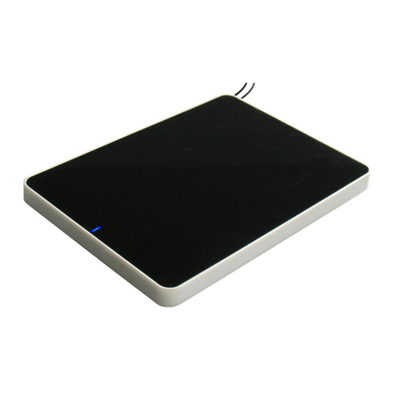
® OBID i-scan Montageanleitung ID ISC.SPAD102 Anzeigeelement (LED) Die blaue LED zeigt den Betriebszustand des Shielded Pad-Readers an: Table 5-1: LED-Anzeige LED-Signal Beschreibung LED blinkt nach Einschalten Readersoftware wird gebootet LED leuchtet Sendeleistung 13,56 MHz eingeschaltet LED blinkt Transponder lesen... -
Seite 13: Technische Daten
6 VA Betriebsfrequenz 13,56 MHz Sendeleistung 1,5 W ± 1 dB Schnittstellen - Ethernet (TCP/IP) (ID ISC.SPAD102-E) - USB (ID ISC.SPAD102-USB) Protokoll Modi - ISO Host Mode - Scan Mode - Notification Mode Unterstützte Transponder... - Seite 14 ® OBID i-scan Montageanleitung ID ISC.SPAD102 Umgebungsbedingungen Temperaturbereich - Betrieb -25...+55°C - Lagerung -25...+70°C Relative Luftfeuchtigkeit 5 bis 95% nicht betauend Angewendete Normen Zulassung Funk - Europa - EN 300 330 - USA - FCC 47 CFR Part 15...
-
Seite 15: Zulassung
® OBID i-scan Montageanleitung ID ISC.SPAD102 6.1 Zulassung 6.1.1 Europa (CE) Die Funkanlage entspricht, bei bestimmungsgemäßer Verwendung den grundlegenden Anforde- rungen des Artikels 3 und den übrigen einschlägigen Bestimmungen der R&TTE Richtlinie 1999/5/EG vom März 99. Equipment Classification gemäß ETSI EN 301 489: Class 2... -
Seite 16: Usa Und Canada
Warning: Changes or modification made to this equipment not expressly approved by FEIG ELECTRONIC GmbH may void the FCC authorization to operate this equipment. FEIG ELECTRONIC GmbH Seite 16 von 32... -
Seite 17: Anhang
® OBID i-scan Montageanleitung ID ISC.SPAD102 Anhang 7.1 Zubehör Zu dem Reader ist folgendes Zubehör zu erhalten. Artikel Nr. Bezeichnung Beschreibung Netzteil 95 - 265V AC Eingangsspannung, (Continental European Plug), 1688.002.00 ID NET.12V-B mit abgewinkelten DC Stecker 2,5mm*5,5mm Output: 12 V DC/ ;...