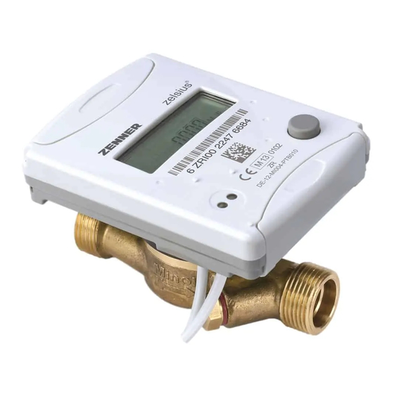
Zenner zelsius C5-IUF Montage- Und Bedienungsanleitung
Thermisches energiemessgerät für heiz- und/oder kühlanlagen mit ultraschall-durchflusssensor iuf optional m-bus, wireless m-bus (oms), lora und 3 ein-/ausgänge qp 0,6/1,5/2,5/3,5/6/10 m³/h
Vorschau ausblenden
Andere Handbücher für zelsius C5-IUF:
- Montage- und bedienungsanleitung (84 Seiten) ,
- Montage- und bedienungsanleitung (88 Seiten) ,
- Montage- und bedienungsanleitung (52 Seiten)
Inhaltsverzeichnis
Werbung
Verfügbare Sprachen
Verfügbare Sprachen
zelsius® C5 - IUF
DE
Montage- und Bedienungsanleitung ............................... 2
Thermisches Energiemessgerät für Heiz- und/oder Kühlanlagen mit
Ultraschall-Durchflusssensor IUF
optional M-Bus, wireless M-Bus (OMS), LoRa® und 3 Ein-/Ausgänge
q
0,6/1,5/2,5/3,5/6/10 m³/h
p
EN
Installation and operating instructions .........................14
Thermal energy meter for heating and/or cooling plants with
ultrasonic flow sensor IUF
optional with M-Bus, wireless M-Bus (OMS), LoRa® and 3 inputs/outputs
q
0.6/1.5/2.5/3.5/6/10 m³/h
p
Werbung
Kapitel
Inhaltsverzeichnis

Verwandte Anleitungen für Zenner zelsius C5-IUF


Inhaltszusammenfassung für Zenner zelsius C5-IUF
- Seite 1 zelsius® C5 - IUF Montage- und Bedienungsanleitung ....... 2 Thermisches Energiemessgerät für Heiz- und/oder Kühlanlagen mit Ultraschall-Durchflusssensor IUF optional M-Bus, wireless M-Bus (OMS), LoRa® und 3 Ein-/Ausgänge 0,6/1,5/2,5/3,5/6/10 m³/h Installation and operating instructions ......14 Thermal energy meter for heating and/or cooling plants with ultrasonic flow sensor IUF optional with M-Bus, wireless M-Bus (OMS), LoRa®...
-
Seite 2: Inhaltsverzeichnis
Deutsch Inhalt Lieferumfang Technische Daten Konformitätshinweise Sicherheitshinweise Elektromagnetische Störungen Pflegehinweise Montageanleitung Sicherheitshinweise zur Montage Einbau des Durchflusssensors (DFS) Einbau des Kugelhahns Montage Wärme-/Kältezähler Montage Temperaturfühler Einbau in Bestandstauchhülsen Inbetriebnahme Impulsein- und -ausgänge (optional) M-Bus (optional) Programmierung der M-Bus-Adresse (optional) Funk (optional) Einfaches Beispiel der Menüführung Legende Statusanzeigen / Fehlercodes Entsorgung... -
Seite 3: Lieferumfang
Lesen Sie unbedingt die Montage- und Sie sich und vermeiden Schäden. Bedienungsanleitung vor der Installati- Prüfen Sie den Inhalt der Verpackung on / Inbetriebnahme. Dadurch schützen vor Montage auf Vollständigkeit. Lieferumfang zelsius® C5-IUF für Wärme- und/oder Kältezählung ■ Zwei Dichtungen ■ Plombiermaterial ■ Wandhalter mit Montagematerial ■... -
Seite 4: Konformitätshinweise
übersteigen. Bei Heizungsanlagen mit Messgerät beigefügt. Neueste Informa- fehlender Temperaturdurchmischung tionen zu diesem Produkt können unter bzw. Temperaturschichtung ist eine www.zenner.de abgerufen werden. Zulaufstrecke von min. 10 x DN am Einbauort vorzusehen. Der Durch- flusssensor ist verschleißfrei, da ohne bewegliche Teile. Es sind keine Ein- oder Auslaufstrecken notwendig. Es ist auf ausreichenden Anlagendruck zur Vermeidung von Kavitation zu achten. -
Seite 5: Einbau Des Durchflusssensors (Dfs)
Bei Heizwassertemperaturen über Nur neues Dichtmaterial verwen- ■ 90 °C sowie kombinierter Wärme- und den, kein Hanf oder ähnliches! Kältemessung oder reiner Kältemes- Dichtflächen säubern und auf sung darf das Rechenwerk zum Schutz Beschädigung kontrollieren. vor zu hohen Temperaturen bzw. äuße- N euen DFS fließrichtungs- und ■ rer Betauung ausschließlich separat auf lagerichtig einbauen. den Wandadapter montiert werden. R echenwerk des Zählers in die ge- ■... -
Seite 6: Einbau In Bestandstauchhülsen
Nach abgeschlossener Inbetrieb- ■ Temperaturfühler für Wärmezähler in nahme den Zähler mit beigelegtem Bestandstauchhülsen“, veröffentlicht in Plombiermaterial gegen unbefugten den PTB Mitteilungen 119 (2009), Heft Ausbau sichern. 4, eingesetzt werden. Die Regelung hat I nbetriebnahmeprotokoll gemäß ■ nach aktuellem Stand den Geltungszeit- PTB-Richtlinie TR K9 ausfüllen. raum bis 30.10.2026. Für die Identi- fikation und Kennzeichnung der in Verbindung mit C5-IUF einsetzbaren Be- standstauchhülsen kann ein Identifika- tions- und Kennzeichnungsset bezogen werden (Artikelnummer 137382). Eine Aufstellung für welche Be- standstauchhülsen C5-IUF zugelassen ist, finden Sie unter www.zenner.de... -
Seite 7: Impulsein- Und -Ausgänge (Optional)
Hinweis: die Auswahl nicht wie nachstehend Nur für Ausführungen mit program- beschrieben aktiviert wurde. Nach 2 mierbarem Einbauort für den Durch- weiteren Minuten ohne zwischenzeit- flusssensor (Bezeichnung „point of liche Tastenbetätigung programmiert installation: see display“ auf dem sich der Zähler automatisch auf den seitlichen Typenschild). Anlagenrücklauf ("outlet"). Der Zähler befindet sich im Ausliefe- rungszustand im Sleep-Mode (Anzeige Aktiviert wird die Auswahl mit dem Tür- SLEEP 1). -
Seite 8: M-Bus (Optional)
Programmierung der M-Bus-Adresse Farbe Anschluss Bedeutung (optional) A nwahl der Anzeige „Adr 000“ in ■ weiß I/O 1 Ein-/Ausgang 1 Ebene 3 (für Zusatzeingänge analog gelb I/O 2 Ein-/Ausgang 2 „Adr1“ bis „Adr3“) grün I/O 3 Ein-/Ausgang 3 T aste für ca. 2 Sekunden drü- ■ cken (bis das Türsymbol wieder Gemeinsame braun Masse für I/O 1-3 erscheint) und dann loslassen. Die rechte Ziffer beginnt zu blinken. Mit jeweils einem kurzen Tastendruck Technische Daten I/O wird der Wert der Ziffer hochge- zählt. - Seite 9 Die Funkschnittstelle ist bei Auslieferung immer deaktiviert. Zur Aktivierung des Gerätes ist keine Software erforderlich. Achtung! Bei zelsius C5 mit LoRa-Schnittstelle empfehlen wir zunächst die zum Gerät gehörenden Key-Informationen (DevEUI, Joi- nEUI und AppKey) auf Ihrer jeweiligen IoT-Plattform zu hinterlegen, bevor Sie das Gerät wie nachfolgend beschrieben aktivieren! Es ist lediglich der ab Werk immer aktivierte Sleep-Modus zu been- den: Geräte, die sich im Sleep-Modus befinden (Anzeige: SLEEP 1), sind mittels mind. fünfsekündigem Tastendruck zu aktivieren bis die Energieanzeige bzw. die Anzeige "r. outlet" (s. auch Seite 7) erscheint. Bei Varianten mit LoRa-Schnittstelle kann mit einem wählbaren Sendeintervall von 15 Minuten bis 24 Stunden ein vom Network Server berechnetes Diagnose- Protokoll abgerufen werden, das die folgenden Daten enthält: Energie (Wärme oder/und Kälte) ■...
-
Seite 10: Einfaches Beispiel Der Menüführung
Einfaches Beispiel der Menüführung Ebene 1 Ebene 2 Wärmeenergie Wärmeenergie vom letzten (Hauptanzeige) Stichtag bis heute Kälteenergie Kälteenergie vom letzten Stichtag bis heute Segmenttest Aktueller Monatsverbrauch Wärmeenergie Datum Stichtag Aktueller Monatsverbrauch Kälteenergie Energie am Stichtag Aktuelles Monatsvolumen Kälteenergie am Stichtag Maximaler Durchfluss Volumen Maximaler Monats-... -
Seite 11: Legende
Ebene 3 Ebene 4 Fühlerart und Einbauort DFS Funktion Impulswertigkeit Ausgang 1 Eingang 1 Seriennummer (bzw. die Funktion Impulswertigkeit rechten 8 Stellen der DevEUI) Ausgang 2 Eingang 2 DevEUI Funktion Impulswertigkeit (die linken 8 Stellen) Ausgang 3 Eingang 3 JoinEUI Restenergie opt. (die rechten 8 Stellen) Schnittstelle JoinEUI (die linken 8 Stellen) Home_NetID Legende T aste kurz drücken (S), zum Blättern von LoRa Status oben nach unten. Nach unterstem Menü- punkt erfolgt ein automatischer Sprung zum obersten Menüpunkt (Schleife). -
Seite 12: Statusanzeigen / Fehlercodes
Statusanzeigen / Fehlercodes Die Symbole in untenstehender Tabelle zeigen den Betriebszustand des Zählers eindeutig an. Sie erscheinen nur in der Hauptanzeige (Energie). Eine vorüber- gehende Anzeige des Warndreiecks kann durch besondere Betriebszustände der Anlage verursacht werden und bedeutet nicht immer eine Gerätestörung. Erst wenn das Symbol dauerhaft ansteht, sollte der Servicebetrieb informiert werden! Symbol Status Maßnahme externe Spannungsversorgung (nur bei M-Bus) Durchfluss vorhanden Anlage / Gerät auf Fehler Achtung! prüfen Symbol blinkend: Datenübertragung ■ Symbol dauernd angezeigt: optische ■... -
Seite 13: Entsorgung
Ende der Nutzungsdauer wieder mit- nehmen und fachgerecht entsorgen. Sofern diesbezüglich keine andere ver- tragliche Regelung getroffen wurde, können alternativ die Altgeräte und Zubehör auch bei unserer Betriebs- stätte in D-09619 Mulda, Talstraße 2 , kostenlos abgegeben werden. Zenner stellt in jedem Fall die fachgerechte Entsorgung sicher. ZENNER International GmbH & Co. KG Römerstadt 6 | 66121 Saarbrücken | Deutschland Telefon +49 681 99 676-30 E-Mail info@zenner.com Telefax +49 681 99 676-3100 Internet www.zenner.de... - Seite 14 English Contents Scope of supply Technical data Declaration of Conformity Safety instructions Electro-magnetic interference Care instructions Installation manual Safety instructions for installation Installation flow sensor (FS) Installation of the ball valve Mounting heat/cooling energy meter Installation of the temperature sensors Installation with existing immersion sleeves Commissioning Pulse inputs and outputs (optional) M-Bus (optional) Programming of M-Bus address (optional) Radio (optional) Simple example of the display menu Legend Status display / Error codes Disposal...
-
Seite 15: Scope Of Supply
Be sure to read the installation and protect yourself and prevent damage. operating manual before installing Check the contents of the packing / commissioning. This allows you to before installation to be complete. Scope of supply z elsius® C5 -IUF compact heat and /or cooling meter ■ Two seals ■... -
Seite 16: Declaration Of Conformity
EU. a straight pipeline of min. 10 x DN has to be provided upstream of the meter. If you have questions, please direct The flow sensor is wear-free, there are them to info@zenner.com no moving parts. No straight lengths of pipe required. It is important to ensure The declaration of conformity is at- adequate system pressure to avoid tached to each measuring instrument. -
Seite 17: Installation Flow Sensor (Fs)
Installation flow sensor (FS) Installation of the temperature sensors Mount ball valves up- and down- The installation of the temperature ■ ■ stream of the flow sensor. sensors should be preferably sym- Consider the correct installa- metrical and as direct installation. ■ tion point. Normally this is the Do not remove the temperatur sen- ■... -
Seite 18: Installation With Existing Immersion Sleeves
Mounting with brass adaptor: ■ – Slide brass screwing with loosely mounted groove pin onto tem- perature sensor in right position – Slide temperature sensor into mounting aid until mechanical stop (28 mm) – Check again, if brass screwing is in right position (the groove pin must Mounting example be pressed in the upper groove which is in the closest position to... -
Seite 19: Pulse Inputs And Outputs (Optional)
Note: activated as described below. After Only for versions with programmable another 2 minutes, the meter programs place of installation of the flow sen- itself automatically to "outlet", if the sor (marking “point of installation: push button hasn't been operated see display” at the type plate on the meanwhile. side). The meter is in the delivery status in The selection is being activated with the sleep mode (SLEEP 1). -
Seite 20: M-Bus (Optional)
Programming of M-Bus address colour connection signification (optional) S elect of the display „Adr 000“ in ■ white I/O 1 In-/Output 1 level 3 (same for the additional yellow I/O 2 In-/Output 2 inputs „Adr1“ to „Adr3“). green I/O 3 In-/Output 3 P ress the button for about 2 ■ seconds (until the door symbol common ground brown for I/O 1-3 reappears) and then release. The right digit starts flashing. With one short push the value of the digit is Technical data I/O incremented. - Seite 21 The radio interface is always deactivated at delivery. To activate the device, no software is required. Attention! For zelsius C5 with LoRa interface, we recommend at first to do the onboarding of the device on your respective IoT platform by putting in the key information belonging to the device (DevEUI, JoinEUI and AppKey) before activating the device as described below! Only the activated sleep mode has to be finished: Devices that are in sleep mode (Display: SLEEP 1) must be activated by at least five second press of the button until the energy display appears or display "r. outlet" (see page 19). In the case of variants with LoRa-interface it is possible to retrieve a diagnostic tele- gram calculated by the network server with the following data: Heating or resp.
-
Seite 22: Simple Example Of The Display Menu
Simple example of the display menu Level 1 Level 2 Heat energy Heat energy difference from (Main display) last due date to now Cooling energy Cooling energy difference from last due date to now Segment test Heat energy difference from 1. of this month to now Date last due date Cooling energy difference from 1. -
Seite 23: Legend
Level 3 Level 4 Sensor type and installation Pulse value Pulse value point of the flow sensor Output 1 Input 1 Serial number (or the right 8 Pulse value Pulse value digits of the DevEUI) Output 2 Input 2 DevEUI Pulse value Pulse value (the left 8 digits) Output 3 Input 3 JoinEUI Opto readout energy (the right 8 digits) Interfaces JoinEUI (the left 8 digits) Home_NetID Legend P ress the button shortly (S) to switch LoRa status... -
Seite 24: Status Display / Error Codes
Status display / Error codes The symbols in the table below show the meter’s operational status. The status messages only appear in the main display (energy). The temporary display of the warning triangle can be caused by special operating states and does not always mean that the device is malfunctioning. However, should the symbol be displayed over a longer period of time, you should contact the service company! Symbol Status... -
Seite 25: Disposal
Your local or municipal authority or the local waste disposal company can give you information relating the collection points for your used equipment. ZENNER will always ensure correct disposal. ZENNER International GmbH & Co. KG Römerstadt 6 | 66121 Saarbrücken | Germany Phone +49 681 99 676-30 E-Mail info@zenner.com Fax... - Seite 26 Notice...
- Seite 28 ZENNER International GmbH & Co. KG Römerstadt 6 66121 Saarbrücken Germany Telefon +49 681 99 676-30 Telefax +49 681 99 676-3100 E-Mail info@zenner.com Internet www.zenner.de...