Herunterladen Inhalt Inhalt Diese Seite drucken
Maico AKE 100 Montage- Und Betriebsanleitung

Maico AKE 100 Montage- Und Betriebsanleitung

Automatische kellerentfeuchtung
Vorschau ausblenden Andere Handbücher für AKE 100:
Inhaltsverzeichnis

Werbung

Verfügbare Sprachen

Verfügbare Sprachen

Montage- und Betriebsanleitung
DE
Automatische Kellerentfeuchtung
Mounting and operating instructions
UK
Automatic cellar dehumidification
Notice de montage et mode d'emploi
FR
Déshumidification automatique des caves
w w w . m a i c o - v e n t i l a t o r e n . c o m
AKE 100

Werbung

Inhaltsverzeichnis
loading

Inhaltszusammenfassung für Maico AKE 100

  • Seite 1 Automatic cellar dehumidification Notice de montage et mode d'emploi Déshumidification automatique des caves AKE 100 w w w . m a i c o - v e n t i l a t o r e n . c o m...
  • Seite 2: Inhaltsverzeichnis

    DE │ Inhaltsverzeichnis AKE 100 Inhaltsverzeichnis Lesen Sie diese Anleitung vor der Montage und ersten Benutzung bitte 1. Lieferumfang ........... 3 sorgfältig durch. Folgen Sie den 2. Qualifikation Fachinstallateur ....3 Anweisungen. Übergeben Sie die 3. Bestimmungsgemäße Verwendung ..3 Anleitung an den Eigentümer zur...
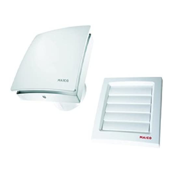
  • Seite 3: Lieferumfang

    Wasser über Böden und Wänden in den Kellerraum. ● Ventilatoreinheit mit Innen-Klimasensor In solchen Fällen kann das Lüf- ● Außenverschlussklappe mit Außen- tungssystem AKE 100 ergänzend Klimasensor und Sensorverbindungskabel für die Kellerentfeuchtung einge- setzt werden. Das Gerät unter- ● Zwei Dichtbänder stützt die Mauerwerkstrocknung...
  • Seite 4: Sicherheitshinweise Beachten

    DE │ 4. Sicherheitshinweise und Warnungen am Ventilator aufhalten. Bei Betrieb Der Ventilator darf in folgenden Situati- unbedingt genügend Abstand halten, damit onen auf keinen Fall eingesetzt werden. dies nicht passieren kann. Entzündungs-/Brandgefahr durch brennbare Materialien, Flüssigkeiten Verletzungsgefahr, wenn oder Gase in der Nähe des Fremdkörper in das Gerät Ventilators.
  • Seite 5: Zuluftnachströmung Innerhalb Der Wohnung

    Luft aus alle Versorgungsstromkreise abschalten Küche, Bad und WC in die Räume, in (Netzsicherung ausschalten), gegen Wieder- denen die AKE 100 installiert ist, einschalten sichern und ein Warnschild überströmen kann. sichtbar anbringen. Ventilator nur komplett ● Ein zu entlüftender Raum muss mit einem montiert betreiben.
  • Seite 6 Entfeuchtung ermöglichen. liegt eine Störung vor, siehe Kapitel Störbehebung. Entfeuchtungserfolg – Taster 1 / Blinken LED 2: Die AKE 100 signalisiert einen Entfeuchtungserfolg durch das Blinken der LED 2 bei einer Reduzierung der Raumfeuchte um mindestens 0,2 g/m im Vergleich zu einem Referenzwert.
  • Seite 7: Umgebungsbedingungen Und Grenzen Für Den Betrieb

    5. Produktinformationen │ DE Manuelles Lüften – Taster 2: Schädigung der Bausubstanz ACHTUNG Die AKE 100 schaltet den Ventilator durch manuellen Lüften vollautomatisch und bedarfsoptimiert Ein zu langes manuelles Lüften ein und aus. Im Auszustand kann der kann bei feuchten Ventilator manuell mit dem Taster 2 Außenbedingungen zu einer...
  • Seite 8: Decke

    DE │ 8. Montagevorbereitungen 1. Im Bereich des Gehäuses für einen 1. Außenverschlussklappe mit Außen- ebenen Untergrund sorgen. Klimasensor auspacken und Außenstück [11] abnehmen. Zum Lösen des 2. Wanddurchbruch anbringen oder Kernloch Außenstücks Rasthaken ( Pfeil) mit bohren: Mindestdurchmesser 105 mm. Schraubendreher entriegeln.
  • Seite 9: Montage

    8. Montagevorbereitungen │ DE 2. Das Sensorverbindungskabel mit Klebeband möglichst auf Unterseite in Wanddurchbruch/Wandhülse befestigen. Für die Verbindung mit der Steuerelektronik werden maximal 10 cm im Ventilatorgehäuse benötigt. 9.3 Gehäuseeinbau Ventilator An AKE100 unbedingt das Dichtband anbringen, damit die 1. Gehäuse [1] in Wanddurchbruch/Wand- Geräte keine Fehlluft von außen hülse stecken (TOP = oben).
  • Seite 10: Elektrischer Anschluss

    DE │ 9. Montage ̶ Elektrischer Anschluss Gerätebeschädigung bei ACHTUNG Kurzschluss. Schutzleiter und nicht benötigte Adern isolieren. 1. Im Gerät nur Einzeladern verlegen. Dazu Mantel der Netzleitung auf einer Länge von 70mm entfernen. Einzelne Adern auf 9 bis 10 mm abisolieren. 2.
  • Seite 11: Inbetriebnahme

    9. Montage │ DE 1. Elektronikabdeckung [6] mit den 3 Rast- 11. Reinigung nasen in die Gehäuseaussparungen I, II und III stecken, bis diese einrasten. Dabei Lebensgefahr durch Strom- die Elektronikabdeckung an den schlag. Pfeilpositionen fest in das Gehäuse GEFAHR Netzsicherung ausschalten.
  • Seite 12: Demontage

    Das Gerät ist nach Ablauf seiner Lebens- dauer nach den in Ihrem Land geltenden Bestimmungen zu entsorgen. 15. Schaltbild Für Schaltbild siehe Seite 36. Impressum: © Maico Elektroapparate- Fabrik GmbH. Deutsche Originalanleitung. Druckfehler, Irrtümer und technische 13. Demontage Änderungen vorbehalten.
  • Seite 13 Table of contents │ UK AKE 100 Table of contents Please read the instructions carefully before mounting and using for the 1. Scope of delivery ........14 first time. Follow the instructions. 2. Specialist installer qualification ....14 Pass these instructions onto the owner for safekeeping.
  • Seite 14: Scope Of Delivery

    ● Two sealing strips through floors and ceilings. ● These mounting and operating instructions In such cases, the AKE 100 ventilation system can be additionally be used for cellar 2. Specialist installer qualification dehumidification. The unit helps...
  • Seite 15 3. Safety instructions and warnings │ UK any flammable materials, liquids or gases A fan that is not installed correctly near the fan, which may ignite in the event of may result in non-intended operation heat or sparks and catch fire. or impermissible operation.
  • Seite 16: Product Information

    Attach a warning sign in a clearly visible 5. Product information place.  Be sure to observe the relevant regula- AKE 100 is a small room fan for dehumidi- tions for electrical installation; e.g. fying rooms, especially cellars and other EN 50110-1, in Germany this is particularly similar rooms.
  • Seite 17 LED 2 blinking briefly. Frost protection: To prevent the room from cooling down, Button 1 Reference value the AKE 100 has a frost protection (Taster 1) determination function. This means that the fan automatically switches off at inside room...
  • Seite 18: Environmental Conditions And Operating Limits

    UK │ 5. Product information Manual ventilation – external 8. Installation preparations button/switch: Optionally to button 2, manual operation can 8.1 Wall take place with an external button or switch, The prescribed minimum distances see wiring diagram in Chapter 15. between the wall and the ceiling To achieve this, an automatic button/switch shown in the figure must be...
  • Seite 19: Duct

    8. Installation preparations │ UK 8.3 Duct 1. Debur edges on the inside of the duct. 2. Perform installation preparations as described in Chapter 8.1. 8.4 External cover 3. Remove the electronics cover [6]. Unlock locking hook ( arrow) with screwdriver. 4.
  • Seite 20: Attachment Of The Sensor Connection Cable

    UK │ 9. Mounting 2. Align housing horizontally and mark the two dowel holes (arrows). 3. Remove housing [1], drill M6 dowel holes with a Ø of 6 mm and insert dowels. 4. Push cable grommet [9] carefully out of housing and remove.
  • Seite 21: Electrical Connection

    9. Mounting │ UK 3. Check position of cable grommet [9]. It must be well sealed. 9.5 Final assembly Before fitting the electronics cover, check the location of the external climate sensor's connection cable to make sure that the mounting of the internal climate sensor is not 7.
  • Seite 22: Start-Up

    UK │ 9. Mounting 2. Insert the supplied internal climate sensor 2. If the designer cover [3] is very dirty, [5] correctly ( arrow X) in the connector remove it carefully from the fan and clean sockets. with water. 3. Fit cover [4]. 3.
  • Seite 23: Dismantling

    15. Wiring diagram For wiring diagram see page 36. Acknowledgements © Maico Elektroapparate-Fabrik GmbH. This instruct- tion is a translation of the German original operating 1. Unlock covers ( arrow) and remove. instructions. We cannot be held responsible for mis- 2.
  • Seite 24 FR │ Sommaire AKE 100 Sommaire Veuillez lire attentivement ces instructions avant le montage et 1. Volume de fourniture ......25 la première utilisation. Suivez les 2. Qualification de l'installateur spécialisé .. 25 instructions. Remettez les 3. Utilisation conforme........ 25 instructions au propriétaire pour...
  • Seite 25: Volume De Fourniture

    Seul un personnel qualifié, disposant de sols ou les murs. Le système connaissances et d'expérience dans la de ventilation AKE 100 peut, technique de ventilation, est autorisé à dans ce cas, être utilisé en effectuer le montage.
  • Seite 26: Consignes De Sécurité Et Avertissements

    FR │ 4. Consignes de sécurité et avertissements Respectez toutes les instructions de 4. Consignes de sécurité et sécurité. avertissements Danger pour les enfants et les Danger immédiat qui, s'il n'est personnes ayant des capacités pas pris en compte, entraîne de physiques, sensorielles ou psychiques graves blessures corporelles ou DANGER...
  • Seite 27 électriques. dans lesquelles l'AKE 100 est installé.  Avant toute installation électrique, couper ● La pièce à ventiler doit être équipée d'une tous les circuits d'alimentation électrique, section d'air entrant impossible à...
  • Seite 28: Informations Produit

    FR │ 5. Informations produit conditions climatiques permettent une 5. Informations produit déshumidification. AKE 100 est un aérateur pour petite pièce servant notamment à déshumidifier les caves et locaux similaires. Cet appareil possède une grille intérieure fixe et est équipé d'un détecteur d'atmosphère intérieure intégré.
  • Seite 29: Conditions Ambiantes Et Limites D'utilisation

    LED 2 : Avec le clignote- connexion de l'alimentation en courant. Une ment de la LED 2, l'AKE 100 signale que la fermeture du contact de commutation déshumidification a réussi et se solde par supérieure à...
  • Seite 30: Caractéristiques Techniques

    FR │ 7. Caractéristiques techniques 8.2 Plafond 7. Caractéristiques techniques Risque de court-circuit et ATTENTION Se référer à la plaque signalétique ou à d'endommagement de Internet. l'appareil résultant de la formation de condensat dans le boîtier de l'aérateur ! 8. Préparatifs de montage Effectuer une isolation thermique des gaines d'air dans les règles 8.1 Mur...
  • Seite 31: Ventilateur

    à la partie inférieure du perçage de cloison / de la gaine murale. La connexion à l'électronique de Sur le modèle AKE 100, poser commande occupe au plus 10 cm impérativement le ruban isolant dans le boîtier du ventilateur.
  • Seite 32: Montage Du Boîtier De Ventilateur

    FR │ 9. Montage 9.3 Montage du boîtier de ventilateur 1. Introduire le boîtier [1] dans le perçage de cloison / la gaine murale (TOP = haut). 5. Introduire le manchon de câble [9] dans le boîtier. Introduire le câble secteur dans l'espace de raccordement de manière à...
  • Seite 33: Montage Final

    9. Montage - Branchement électrique │ FR Risque de court-circuit et d'en- ATTENTION Endommagement de l'appa- ATTENTION dommagement de l'appareil ! reil en cas de court-circuit ! Pénétration d'humidité en cas Isoler le conducteur de de mauvais positionnement protection et les conducteurs du cache électronique.
  • Seite 34: Entretien

    9. Montage │ FR 4. Poser le cache de protection design [3]. Les deux Pas de tension du secteur. LED son La mémorisation de la valeur de Contrôler si le fusible secteur éteintes référence est signalée par le fonctionne correctement. Le clignotement de la LED 1.
  • Seite 35: Élimination

    3. Retirer le câble secteur. Voir le schéma de branchement à la page 36. 4. Démonter le ventilateur. Mentions légales © Maico Elektroapparate Fabrik GmbH. Cette instruc-tion est une traduction de l'instruction allemande originale. Sous réserve de fautes d'impression, d'erreurs et de modifications...
  • Seite 36: Schaltbild

    Connection for optional supply air element, e.g. ECA 11 E Raccord pour élément d'air entrant en option, p. ex ECA 11 E Maico Elektroapparate-Fabrik GmbH • Steinbeisstr. 20 • 78056 Villingen-Schwenningen • Germany • Service +49 7720 6940 • info@maico.de...

Inhaltsverzeichnis