Herunterladen Inhalt Inhalt Diese Seite drucken
Inhaltsverzeichnis

Werbung

Verfügbare Sprachen

Verfügbare Sprachen

RACK TOWER 1KVA-3KVA
UPS User's manual
DE
BEDIENUNGSANLEITUNG
PL
INSTRUKCJA OBSŁUGI
FR
MODE D'EMPLOI

Werbung

Inhaltsverzeichnis
loading

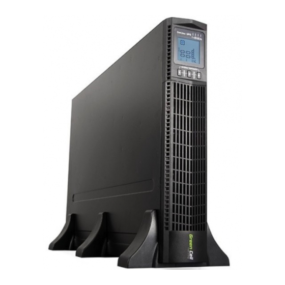
Inhaltszusammenfassung für Green Cell 1KVAS-EBP

  • Seite 1 RACK TOWER 1KVA-3KVA UPS User’s manual BEDIENUNGSANLEITUNG INSTRUKCJA OBSŁUGI MODE D’EMPLOI...
  • Seite 2: Inhaltsverzeichnis

    Table of contents INTRODUCTION SAFETY WARNINGS INSTALLATION OPERATION COMMUNICATION UPS MAINTENANCE SPECIFICATIONS TROUBLESHOOTING EINLEITUNG SICHERHEITSWARNUNGEN INSTALLATION BETRIEB ANSCHLUSS USV-WARTUNG TECHNISCHE DATEN FEHLERBEHEBUNG WSTĘP OSTRZEŻENIA DOTYCZĄCE BEZPIECZEŃSTWA INSTALACJA EKSPLOATACJA POŁĄCZENIE KONSERWACJA UPS DANE TECHNICZNE ROZWIĄZYWANIE PROBLEMÓW...
  • Seite 3 INTRODUCTION CONSIGNES DE SÉCURITÉ INSTALLATION FONCTIONNEMENT COMMUNICATION OPTIONS DE COMMUNICATION ET RACCORDS DE CONTRÔLE CARACTÉRISTIQUES TECHNIQUES DÉPANNAGE...
  • Seite 4 Special Symbols The following are examples of symbols used on the UPS or accessories to alert you to important information: RISK OF ELECTRIC SHOCK - Observe the warning associated with the risk of electric shock symbol. CAUTION,need your attention This symbol indicates that you should not discard the UPS or the UPS batteries in the trash. This product contains sealed, lead‐acid batteries and must be disposed of properly.
  • Seite 5 1 Introduction This UPS protects your sensitive electronic equipment from most common power problems, including power failures, power sags, power surges, brownouts, line noise, high voltage spikes, frequency variations, switching transients, and harmonic distortion. Power outages might occur unexpectedly and power quality can be erratic. These power problems have potential to corrupt critical data, destroy unsaved work sessions, and damage hardware —...
  • Seite 6: Safety Warnings

    2 Safety Warnings IMPORTANT SAFETY INSTRUCTIONS - SAVE THESE INSTRUCTIONS This manual contains important instructions that you should follow during installation and maintenance of the UPS and batteries. Please read all instructions before operating the equipment and save this manual for future reference. DANGER The UPS contains LETHAL VOLTAGES.
  • Seite 7: Unpacking The Cabinet

    UNPACKING THE CABINET CAUTION • Unpacking the cabinet in a low-temperature environment may cause condensation to occur in and on the cabinet. Do not install the cabinet until the inside and outside of the cabinet are absolutely dry (hazard of electric shock). •...
  • Seite 8: Rackmount Setup

    RACKMOUNT SETUP CAUTION The cabinet is heavy. Removing the cabinet from its carton requires a minimum of two people. If installing optional EBP (S), make sure to install the EBP (S) directly below the UPS so that all wiring between the cabinets is installed behind the front covers and inaccessible to users. NOTE Mounting rails are required for each individual cabinet TO INSTALL THE RAIL KIT: 1.
  • Seite 9 1. Mounting Bracket 2. M4x8 Flat-Head Screws (4 places) FIG 5: Installing the Mounting Brackets 9. Align the mounting brackets with the screw holes on each side of the UPS and fi x with the supplied M4×8 fl at-he- ad screws (see FIG. 5) 10.
  • Seite 10: Installation

    FIG 8: Connecting the UPS Internal Batteries FIG 7: Extract UPS front cover 1. Battery 1. Top EBP Cable Knockout 2. Black wire 2. EBP Cover Hooks (2places) 3. Red wire 3. Insert the two thin-wall into the slot FIG 9: Long backup external battery connection FIG 10 2.
  • Seite 11 7. If an emergency power-off (disconnect) switch is required by local codes, see “Remote Emergency Power-off” (REPO) to install the REPO switch before powering on the UPS. 8. Continue to “UPS Initial Startup”. CONNECTING THE EBP (S) To install the optional EBP (s) for a UPS: 1.
  • Seite 12 RACKMOUNT CONVERTED TO TOWER INSTALLATION Rackmount converted to Tower plastic base installation If an EBP is needed to be placed in the middle, the assembly of plastic base is similar. The difference is that two 1U plastic base extended boards are added in the middle. (as the following shows) 1.
  • Seite 13: Ups Initial Startup

    1. Battery 2. Black wire 3. Red wire FIG 16: The installation for UPS and battery box FIG 17: Long backup external battery connection The installation between UPS and EBPS can be referred to Fig.16 1. Install the base, then place the RT UPS on the base one by one as Fig.16 shows. 2.
  • Seite 14: Operation

    12. If you installed an optional EPO, test the EPO function: Activate the external EPO switch. Verify the status change on the UPS display. Deactivate the external EPO switch and restart the UPS. NOTE: The internal batteries charge to 80% capacity in less than 5 hours. However, we recommend that NOTE: The internal batteries charge to 80% capacity in less than 5 hours.
  • Seite 15 Table 3: The corresponding working status of indications N° Working status Indication WARNING Remarks Line mode Normal voltage None High/low voltage protec- Once every four tion, turn to battery mode seconds Battery mode Normal voltage Once every four seconds Battery Voltage abnormal Once per second WARNING Bypass mode...
  • Seite 16: Display Functions

    DISPLAY FUNCTIONS As the default or after 5 minutes of inactivity, the LCD displays the output parameters. The backlit LCD automatically dims after 5 minutes of inactivity. Press any button to restore the screen. LCD display comprises numerical value section, capacity graphics section, fan-status graphics section and charger- -status graphics section , refer to Table 4 for detail.
  • Seite 17 PARAMETERS INQUIRING Press and hold the scroll key for more than half a second (less than 2 seconds) to inquire about items. The inquired items include input, battery, output, load, temperature. Press and hold the scroll key for more than 2 seconds, LCD begins to display the items circularly and orderly which transfer to another every 2 seconds.
  • Seite 18: User Settings

    USER SETTINGS The UPS has setting functions. This user settings can be done under any kind of UPS working mode. The setting will take effect under certain condition. Below table describes how to set the UPS. Table 6. User Settings ECO FUNCTION SETTING (1) 1.
  • Seite 19 lect the numerical value in accordance with “OPU” function. The provided voltages are 208v, 220v, 230v, 240,you can choose any one of them by yourself (The default is 220v). 3. Confi rm the output voltage selecting interface. After selecting numerical value, press and hold the function set- ting key for more than half a second (less than 2 seconds).
  • Seite 20 FREQUENCY CONVERTER MODE SETTING (7) 1. Enter the setting interface. Press and hold the function setting key for more than 2 seconds, then come to setting interface, Press and hold the scroll keyfor more than half a second (less than 2 seconds), select the func- tion setting, choose output frequency setting interface, the letters “OPF”...
  • Seite 21: Startup / Operation

    Fault When the UPS has fault. The WARNING red LED is on and the buzzer Mode beeps. The UPS will turn to fault mode. The UPS cuts off the output and the LCD display fault codes. At the moment, you can press the mute key to make the buzzer stop beeping temporarily to wait for maintenance.
  • Seite 22: Communication

    CONFIGURING BATTERY SETTINGS Set the UPS for the number of EBPs installed. To ensure maximum battery runtime, confi gure the UPS for the correct number of EBPs, refer to Table 8 for the appropriate setting of battery numbers and type. Use the up and down scroll keys to select the number of battery strings according to your UPS confi...
  • Seite 23 COMMUNICATION OPTIONS AND CONTROL TERMINALS Installing Communication Options and Control Terminals To install the communication options and control terminals: 1. Install the appropriate connectivity card and/or necessary cable (s) and connect the cables to the appropriate location. 2. Route and tie the cable (s) out of the way. 3.
  • Seite 24: Emergency Power-Off

    FIG 22: Optional Connectivity Cards NOTE: Before installing the connectivity card , please remove the clip from the bay. Refer to the user’s manual of the appropriate cards. EMERGENCY POWER-OFF EPO is used to shut down the UPS from a distance. This feature can be used for shutting down the load and the UPS by thermal relay, for instance in the event of room overtemperature.
  • Seite 25: Load Segments

    NOTE Depending on user confi guration, the pins must be shorted or opened to keep the UPS running. To NOTE Depending on user confi guration, the pins must be shorted or opened to keep the UPS running. To restart the UPS, reconnect (re-open) the EPO connector pins and turn on the UPS manually. Maximum restart the UPS, reconnect (re-open) the EPO connector pins and turn on the UPS manually.
  • Seite 26: Replacing Batteries

    48 hours after long-term storage. If optional EBPs are installed, see the recharge times listed in Table 21. Check the battery recharge date on the shipping carton label. If the date is expired and the batteries were never recharged, do not use the UPS.
  • Seite 27 1. Insert the thin-wall into the slot. 2. M4X8 Pan-Head Screws FIG 25: The Installation for baffl e of battery pack (2places) FIG 26: Remove the battery park 1. Insert the thin-wall into the slot 2. M4X8 Pan -Head Screws (4 places) FIG 27: Installation for battery pack EN / 27...
  • Seite 28: Model Specifications

    Compatible Connectivity Cards SNMP card /Contact Relay Card Communication Ports RS232 (DB-9) 2400bps Table 11: Extended Battery Model EBP Model Confi guration Battery Voltage For Power Ratings 1KVAS-EBP 24VDC 1000 VA 1.5KVAS-EBP 36VDC 1000/1500 VA 2KVAS-EBP 48VDC 2000 VA 3KVAS-EBP...
  • Seite 29 Table 14: Electrical Input (All Models) Nominal Frequency 50/60 Hz auto-sensing Frequency Range 45–55 Hz (50Hz)/55-65Hz (60Hz) before transfer to battery Bypass Voltage Range +5%,+10%,+15%,+25% (+25% by default),-20%,-30%,-45% (-45% by default) Table 15: Electrical Input (All Models) Model Default Input Voltage/Current Selectable Input Voltages Voltage Range at 100%...
  • Seite 30 Output Overload 108%±5%–150%±5%: Load transfers to Fault mode after 30 seconds. (Battery Mode) 150%±5%–200%±5%: Load transfers to Fault mode after 300 ms. >200%±5%: Load transfers to Fault mode after 20 ms. Voltage Waveform Sine wave Harmonic Distortion <3% THD on linear load; <5% THD on non-linear load Transfer Time Online mode: 0 ms (no break) High Effi...
  • Seite 31: Troubleshooting

    Storage Temperature -20°C to 40°C (-4°F to 104°F) with batteries -25°C to 55°C (-13°F to 131°F) without batteries Transit Temperature -25°C to 55°C (-13°F to 131°F) Relative Humidity 0–90% noncondensing Operating Altitude Up to 3,000 meters (9,843 ft) above sea level REAR COVERS 1.
  • Seite 32 Table 23 Fault Cause Solution The “INPUT” letters on LCD display Anti-connection of mains live and Re-connect the input power cable section fl ashes neutral or mains is out of range and make a correct connection Battery capacity indicator fl ashes Battery low voltage or battery Check UPS battery, connect battery disconnected...
  • Seite 33 Table 24: Warning and Fault Codes Line Bat Test Mode Mode Mode Mode Mode Voltage error High positive voltage High negative voltage Low positive voltaget Low negative voltage Unbalanced voltage Soft inverter Inverter error High risk Minimal risk Soft fail Discharge voltage error Overheating error Loading error...
  • Seite 34 Spezielle Symbole Nachfolgend fi nden Sie Beispiele für Symbole, die auf der USV oder ihrem Zubehör verwendet werden, um vor wichti- gen Informationen zu warnen: STROMSCHLAG - Beachten Sie die Warnungen bezüglich der Gefahr eines elektrischen Schlages VORSICHT, Vorsicht ist erfordert Dieses Symbol weist darauf hin, dass die USV oder die Batterie nicht in den Müll entsorgt werden darf.
  • Seite 35: Einleitung

    1 Einleitung Die USV schützt empfi ndliche elektronische Geräte vor den häufi gsten Energieproblemen, einschließlich Netzausfäl- len, Stromausfällen, Überspannungen, Spannungsabfällen, Leitungsstörungen, hohen Spannungsspitzen, Schaltfrequ- enzänderungen, Überspannungen und harmonischen Verzerrungen. Spannungsfehler können unerwartet auftreten und die Stromqualität kann instabil sein. Diese Energieprobleme haben das Potenzial, kritische Daten zu verändern, nicht gespeicherte Arbeitssitzungen und Geräte zu zerstören - was zu stundenlangen Produktivitätsverlusten und kostspieligen Reparaturen führt.
  • Seite 36: Überprüfung Der Anlage

    WARNUNG • Der USV-Ausgang kann Hochspannung führen, auch wenn das Netzteil nicht an das Netz angeschlos- sen ist. • Um das Risiko eines Brandes oder Stromschlags zu verringern, installieren Sie die USV in einer tempera- tur- und feuchtigkeitskontrollierten, kontaminationsfreien Innenumgebung. Die Umgebungstemperatur darf 40°...
  • Seite 37: Überprüfung Der Ausrüstung

    Stellen Sie das Gehäuse an einem geeigneten Ort auf, der einen angemessenen Luftstrom hat und frei von Feuchtig- keit, brennbaren Substanzen und Korrosion ist. ÜBERPRÜFUNG DER AUSRÜSTUNG Überprüfung der Ausrüstung umfasst: • USV-Handbuch • CD mit Softwarepaket • USB-Kabel • Netzkabel (Ein- und Ausgang) •...
  • Seite 38 1. hintere Schienen 2. Schirmschrauben 3. Rechte Schiene 4. Linke Schiene Abb.3: Schienenschutz 2. Wählen Sie die entsprechende Größe im Schrank für die Positionierung der Stromversorgung (siehe Abbildung 4). Die Schiene nimmt vier Punkte auf der Vorder- und Rückseite des Gehäuses ein. 3.
  • Seite 39 11. Legen Sie die USV und alle anderen optionalen Batterien in den Schrank. 12. Sichern Sie die Vorderseite der Stromversorgung mit einer M5 × 12-Schraube und einer M5-Mutter auf jeder Seite (siehe Abbildung 6). Installieren Sie die untere Schraube auf jeder Seite durch das untere Loch der Montagehalte- rung und das untere Loch der Schiene.
  • Seite 40 Abb.7: Öffnen der Vorderseite einer USV Abb.8: Anschluss der internen UPS-Batterien 1. Batterie 1. EBP Kabelbuchse 2. Schwarzer Kabel 2. Haken der Kappe EBP (2 Plätze) 3. Roter Kabel 3. Zwei fl ache Elemente in den Schlitz einführen Abb.9: Anschluss externer Batterien über lange Abb.10 Back-UPS kationsanschlüsse das entsprechende Kabel.
  • Seite 41 HINWEIS: Beim Anschluss von EBP an die USV kann es zu einer geringen Lichtbogenbildung kommen. Das ist normal und schadet einer Person nicht. Schließen Sie das EBP-Kabel schnell und fest an den USV-Batterieanschluss an. 5. Schließen Sie das/die EBP-Kabel an den/die Batteriestecker an, wie auf ABB.dargestellt. Schließen Sie maximal 4 (vier) EBPs an die Stromversorgung an.
  • Seite 42: Gestell - Rack Umgebaut Für Die Turmmontage

    GESTELL – RACK UMGEBAUT FÜR DIE TURMMONTAGE Gestell – Rack umgebaut für die Turmmontage 1. zwei Kunststoff-Basisgriffe kreuzen sich wie im Abb.14 dargestellt 2. an einer Kreuzung abfl achen 3. Muss das EBP in der Mitte platziert werden, ist die Grundfaltung ähnlich. Der Unterschied besteht darin, dass in der Mitte zwei Kunststoffsockel hinzugefügt werden (wie unten gezeigt) 1.
  • Seite 43 Installation zwischen USV und EBPS unter Bezugnahme auf dem Abb.16 1. Installieren Sie die Sockel und setzen Sie dann die RT USV nacheinander auf den Sockel - wie im Abb.16 darge- stellt. 2. Die Abdeckung und das Kabel für die Stromversorgung und das EBPS sind die gleichen wie bei RT. (Zur Installa- tion des optionalen EBP-sy für USV) 1.
  • Seite 44: Betrieb

    HINWEIS: Beim Erstbetriebnahme müssen Sie die Ausgangsspannung für die USV vor dem nächsten Start der USV in der Ausgangsspannungseinstellung einstellen. 11. Wenn ein optionales EPA installiert ist, testen Sie bitte dessen Funktionalität: Schalten Sie den externen EPA-Schalter ein. Prüfen Sie, ob es eine Statusänderungauf der UPS-Anzeige gibt. Schalten Sie den externen EPO-Schalter aus und starten Sie die USV neu.
  • Seite 45 Tabelle 3: Zustand entsprechend dem Status der Indikatoren N° Status der Arbeiet Bezeichnung Warnung HINWEISe Lineare Arbeit normall kein Hoch-/Niederspannun- einmal alle 4 Sekunden gsschutz, Umschaltung auf Batteriebetrieb Batteriebetrieb Normale Spannung einmal alle 4 Sekunden Warnung vor anormaler einmal pro Sekunde Batteriespannung Bypassbetrieb Normale Spannung der...
  • Seite 46: Anzeigefunktionen

    ANZEIGEFUNKTIONEN Das Display zeigt standardmäßig die Parameter des Ausgangsstroms an oder verfällt nach 5 Minuten Inaktivität. Die Anzeige erlischt automatisch nach 5 Minuten Inaktivität. Durch Drücken einer beliebigen Taste wird die Hinter- grundbeleuchtung wieder hergestellt. Das Display enthält grafi sche Informationen zu Kapazität, Kühl- und Ladestatus sowie numerische Informationen zu Spannung, Ausgangsfrequenz usw.Details fi...
  • Seite 47: Überprüfung Der Parameter

    ÜBERPRÜFUNG DER PARAMETER Drücken sie die Taste und halten länger als 2 Sekunden gedrückt, um Informationen über ausgewählte Pa- rameter zu erhalten. Dazu gehören Parameter wie: Ausgangs- und Eingangsstrom, Batteriekapazität und -spannung, Temperatur und Last. Drücken Sie und halten Sie die Taste länger als 2 Sekunden gedrückt, und die LCD-Anzeige beginnt zu blinken.
  • Seite 48: Benutzereinstellungen

    Verbleibende Lebens- Zeigt die verbleibende Zeit an, die das Gerät bei dauer der Batterie der aktuellen Last halten kann. Die Zahl gibt die Anzahl der Minuten an. Wie Sie in der folgenden Grafi k sehen können, verbleiben noch 686 Minuten zum Entladen. Systemsoftwarenver- Systemsoftwareversion: Zeigt die Systemso- sion...
  • Seite 49: Ausgangsspannungseinstellungen

    weniger als zwei Sekunden. 3. Bestätigen Sie die BPS-Einstellungen. Nachdem Sie EIN oder AUS gewählt haben, drücken und halten Sie die Funktionstaste länger als eine halbe Sekunde (weniger als 2). Nun ist die BPS-Einstellung abgeschlossen und ON oder OFF unter BPS leuchtet auf, ohne zu blinken. 4.
  • Seite 50: Einstellungen Der Epo-Ausgangspolarität

    3. Bestätigung der Auswahl der maximalen Batteriespannungseinstellung. Halten Sie nach Auswahl des numerischen Werts die Funktionstaste länger als eine halbe Sekunde (weniger als 2) gedrückt. Die Einstellung für die maximale Batte- rieladung wird jetzt bestätigt. 4. Beenden Sie die Schnittstelle. Halten Sie die Funktionstaste länger als eine halbe Sekunde (weniger als 2) gedrückt.
  • Seite 51: Ein- Und Ausschalten Des Geräts

    Modus Eine gelbe LED und alle 2 Minuten ein Alarmton. -„Bypass” Die rote Warn-LED leuchtet während des Pieptons, die Last- und Batteriekapazitätsanzeigen werden auf dem LCD-Display angezeigt. Die Bypass-Toleranz kann über die Schnittstelle auf dem LCD- -Display eingestellt werden. Unter den folgenden Umständen geht die USV in den Bypass-Modus: Der Bypass wurde vom Benutzer eingestellt, die USV ist ausgeschal- tet.
  • Seite 52 USV im Modus „Line” ausgeschaltet 1. Halten Sie die Taste länger als eine halbe Sekunde gedrückt, um die USV und den Wechselrichter auszuschalten. 2. Wenn die USV ausgeschaltet wird, erlöschen die LEDs und der Ausgangsstrom wird abgeschaltet. Wenn Sie die Ausgangsspannung beibehalten müssen, stellen Sie BPS im Menü...
  • Seite 53: Anschluss

    5 Anschluss Dieser Abschnitt beschreibt: • Kommunikationsanschlüsse (RS-232 und USB) • Kommunikationskarten • Notfall-Stopp (EPO) • Empfangende Segmente • UPSilon2000 Energieverwaltungs-Software 1. Ausgangsbuchse 2. Akku-Buchse 3. Innenschlitz (sog. Slot) SNMP 4. Schutz des Netzes vor Kurzschlüssen 5. Lüfter 6. RS232, USB 7.
  • Seite 54: Notabschaltung (Emergency Power-Off)

    RS-232- UND USB-KOMMUNIKATIONSANSCHLÜSSE Um die Kommunikation zwischen der USV und dem Computer herzustellen, schließen Sie den Compu- ter mit dem entsprechenden Kommunikationskabel (USB-Kabel im Lieferumfang enthalten) an einen der USV-Kommunikationsanschlüsse an, wobei der Kommunikationsanschluss vorhanden sein muss (Abbildungen 19, 20). Sobald das Kommunikationskabel installiert ist, kann die Energieverwaltungs- software Daten mit der USV austauschen.
  • Seite 55: Anmerkung

    WARNUNG EPO 60950 ist eine Schutzschaltung für sehr niedrige Spannungen (SELV) der IEC-Schaltung. Dieser Stromkreis muss durch eine verstärkte Isolierung von allen gefährlichen Spannungskreisen getrennt bleiben. VORSICHT EPO darf nicht an Schaltkreise angeschlossen werden, die isoliert sind. Der EPO-Schaltermuss eine Mindestspannung von 24 VDC und 20 mA haben und muss ein dedizierter Schnappschalter sein, der nicht an einen anderen Stromkreis angeschlossen ist.
  • Seite 56: Usv-Wartung

    Jede Stromversorgung hat zwei Lastsegmente: • Lastsegment 1: Die Umlenkung der Batteriespannung dieses Segments kann über den LCD-Bildschirm eingestellt werden. • Lastsegment 2: Siehe „Rückwand”. für die Lastsegmente jedes USV-Modells.Oprogramowanie UPSilon2000 Power Management UPSILON2000 ENERGIEVERWALTUNGS-SOFTWARE Jede USV wird mit der UPSilon2000 Verwaltungssoftware geliefert. Um mit der Installation von UPSilon2000 zu beginnen, lesen Sie die mit der Software-Suite-CD gelieferten Anweisungen.
  • Seite 57: Ersetzen Von Rt Ups Und Ebps

    von Werkzeugen und Metallteilen auf Batterien 4) Verwendung von Gummihandschuhen und Schuhen mit Gummiisolierung, z.B.aus Gummi. • Wenn Sie Batterien austauschen, ersetzen Sie die Batterie durch genau denselben Typ wie das Original- produkt. Wenden Sie sich an Ihr Servicezentrum, um neue, geeignete Batterien zu bestellen. •...
  • Seite 58: Erprobung Neuer Batterien

    1. Schieben Sie 2 fl ache Teile in die Schlitze 2. SchraubenM4X8 (4 Plätze) Abb.27: Installation von Akkus ERPROBUNG NEUER BATTERIEN Um die neuen Batterien zu testen, müssen Sie: 1. Schließen Sie die USV für 48 Stunden an, um die Batterien aufzuladen. 2.
  • Seite 59: Kommunikationsports

    Kommunikationsports Unabhängiger Kommunikationsport für Verbindungskarten verfügbar Kompatible Verbindungskarten Karte SNMP Kommunikationsports RS232 (DB-9) 2400bps Tabelle 11: Modelle mit vergrößerten Batterien Model EBP Konfi guration Batteriespannung Nennleistung 1KVAS-EBP 24VDC 1000 VA 1.5KVAS-EBP 36VDC 1000/1500 VA 2KVAS-EBP 48VDC 2000 VA 3KVAS-EBP 72VDC...
  • Seite 60 Tabelle 15: Eingabeparameter (alle Modelle) Standardeingangsspannung (Spannung / Strom) Spannung zur Auswahl Spannungsbereich bei 100% Last 1KVAS/1KVAH 230V / 4.4A 200, 208, 220, 230, 240 160 - 290Vac 1.5KVAS/1.5KVAH 230V / 6,5A 200, 208, 220, 230, 240 160 - 290Vac 2KVAS/2KVAH 230V / 8,7A 200, 208, 220, 230, 240...
  • Seite 61 Übertragungszeit Tryb online: 0 ms (ohne Pause) Hochleistungsmodus: 10ms maksimum (durch den Verlust der Nützlichkeit) Leistungsverhältnis Koeffi zient des Spitzenwertes Tabelle 18: Elektrische Anschlüsse Ausgang (Alle Modelle) Modell Ausgangsanschlüsse Ausgangsleitungen 1K - RT (IEC C13-10A)*6 IEC320 C14-10A 1.5K - RT (IEC C13-10A)*6 IEC320 C14-10A 2K - RT...
  • Seite 62 Höhe, in der der Transit Bis zu 10.000 Meter über dem Meeresspiegel (32,808 ft) stattfi ndet Hörbare Lautstärke <55 dBA in einem Abstand von 1 Meter Laufende Verluste <1.5 mA Tableau 20 Modell Bemerkungen Standardeinheit 1KVAS Internes Ladegerät 1.4A , 2 Batteriestücke der 9AH 1.5KVAS Internes Ladegerät.4A, 3 Batteriestücke 9AH 2KVAS...
  • Seite 63: Fehlerbehebung

    1. Ausgangsbuchse 2. Akku-Buchse 3. Innenschlitz (sog. Slot) SNMP 4. Schutz des Netzes vor Kurzschlüssen 5. Lüfter 6. RS232, USB 7. AC Buchse 8. Reset, 9. EPO 8 Fehlerbehebung Die folgenden Meldungen sind die Informationen, die Sie bei Problemen auf UPS fi nden. Die Benutzer können beurteilen, ob die Fehlfunktion durch externe Faktoren verursacht wird, und lernen, wie sie mit dieser Fehlfunktion umgehen können, indem sie die Informationen vollständig nutzen.
  • Seite 64 Kurze Haltezeit Batterien nicht vollständig geladen Schließen Sie die USV für mehr als 8 Stunden an das Netzwerk an. Laden Sie die Batterie auf Überlastung der USV Prüfen Sie die Lastauslastung, entfernen Sie unnötige Geräte. Alte Batterien Wenn die Batterien ersetzt werden müssen, wenden Sie sich an Ihren Händler oder ein autorisiertes Servicezentrum.
  • Seite 65 Tabelle 24: Kody błędu dla zasilaczy typu RT Bypas- Linien- Batterie- Batterie- Ecomo- smodus -Modus modus -Prüfmo- Spannungsfehler Hohe positive Spannung Hohe negative Spannung Niedrige positive Span- nung Niedrige negative Spannung Unsymmetrische Span- nung Weicher Wechselrichter Wechselrichter-Fehler Hohes Risiko Geringes Risiko Softfail Fehler bei der Entlade- spannung...
  • Seite 66 Symbole Specjalne Poniżej przedstawiono przykłady symboli użytych na UPS lub akcesoriów do ostrzegania przed ważnymi informacja- RYZYKO PORAŻENIEM - Należy zwrócić uwagę na ostrzeżenia związane z ryzykiem porażenia prądem UWAGA, wymagają uwagi Ten symbol oznacza, że nie należy wyrzucać zasilacza UPS lub baterii do śmieci. Produkt zawiera zaplom- bowane akumulatory ołowiowo-kwasowe, które muszą...
  • Seite 67: Wstęp

    1 Wstęp UPS chroni wrażliwy sprzęt elektroniczny przed najczęstszymi problemami energetycznymi, w tym awarii zasilania, zanikami zasilania, przepięciami, spadkami napięcia, zakłóceniami linii, skokami wysokiego napięcia, zmianami częstotliwości przełączania, przepięciami i zniekształceniami harmonicznymi. Zaniki napięcia mogą pojawić się nieoczekiwanie i jakość zasilania może być niestabilna. Te problemy z zasilaniem mają...
  • Seite 68: Instalacja

    OSTRZEŻENIE • UPS zawiera własne źródło energii (baterie). Wyjście UPS może przewodzić duże napięcie, nawet gdy zasilacz nie jest podłączony do zasilania sieciowego. • Aby zmniejszyć ryzyko pożaru lub porażenia prądem elektrycznym, należy instalować UPS w kontrolo- wanej temperaturze i wilgotności, w środowisku wewnętrznym, wolnym od zanieczyszczeń. Tempera- tura otoczenia nie może przekraczać...
  • Seite 69 Umieścić obudowę w odpowiednim obszarze, który ma prawidłowy przepływ powietrza i jest wolny od wilgoci, łatwo- palnych substancji oraz korozji. SPRAWDZANIE WYPOSAŻENIA Wyposażenie obejmuje: • Podręcznik UPS • CD z pakietem oprogramowania • Kabel USB • Przewód zasilający (wejście i wyjście) •...
  • Seite 70 1. Tylnie szyny 2. Wkręty parasolowe m5 3. Prawa szyna 4. Lewa szyna Rysunek 3: Zabezpieczenie szyn 2. Wybrać odpowiedni rozmiar w szafi e do pozycjonowania zasilacza (patrz rys. 4). Szyna zajmuje cztery punkty z przodu i z tyłu szafy. 3.
  • Seite 71 12. Zabezpieczyć przód zasilacza przy użyciu jednej śruby M5 × 12 i jeden nakrętki M5 z każdej strony (patrz rys. 6). Zamontować dolną śrubę na każdej stronie, przez dolny otwór wspornika mocującego oraz dolny otwór szyny. Powtórzyć dla wszystkich opcjonalnych szaf. 13.
  • Seite 72 Rysunek 7: Otwieranie frontu szafy Rysunek 8: Podłączenie baterii wewnętrznych UPS 1. Bateria 1. Gniazdo kabla EBP 2. Czarny kabel 2. Zaczepy pokrywy EBP (2 miejsca) 3. Czerwony kabel 3. Wsunąć dwa płaskie elementy w sloty Rysunek 9: Podłączenie baterii zewnętrznych Rysunek 10 przez długi Backup 6.
  • Seite 73 5. Podłączyć kabel (i) EBP do złącza (y) baterii, jak przedstawiono na Rysunek. 1 Do zasilacza można podpiąć maksymalnie 4 (cztery) EBPs. Połączyć czarny kabel do czarnego kabla. Mocno docisnąć w celu zapewnienia dobrego połączenia. Aby połączyć drugi EBP należy odpiąć złącze EBP od pierwszego EBP i delikatnie pociągnąć. Pozwoli to na przedłu- żenie przewodów dla złącza EBP do drugiego EBP.
  • Seite 74 RACK - KONWERTOWANE DO MONTAŻU WIEŻY Konwersja rack do wersji tower 1. dwa plastikowe uchwyty bazowe skrzyżować jak na Rys. 14 2. spłaszczyć po skrzyżowaniu 3. Jeśli istnieje potrzebna aby EBP był umieszczony pośrodku, składanie podstawy jest podobne. Różnica polega na tym, że dwie plastikowe podstawy dodane są...
  • Seite 75 Instalacja pomiędzy UPS i EBPS w odniesieniu do Rys.16 1. Zainstalować podstawy, a następnie umieścić RT UPS na bazie jeden po drugim - jak pokazuje Rys.16. 2. Instalacja pokrywy i kabla dla zasilacza i EBPS są takie same jak w przypadku RT. (Aby zainstalować opcjonalnie EBP-sy dla UPS) 1.
  • Seite 76: Eksploatacja

    12. Jeśli zainstalowano opcjonalny EPO, prosimy o przetestowanie jego funkcjonalności: Włączyć zewnętrzny włącz- nik EPO. Sprawdzić, czy dokonała się zmiana statusu na wyświetlaczu UPS. Wyłączyć zewnętrzny wyłącznik EPO i  uruchom ponownie UPS. UWAGA: Wbudowane akumulatory są ładowane do 80% pojemności w czasie krótszym niż 5 godzin. Zaleca się...
  • Seite 77 PL / 77...
  • Seite 78 FUNKCJE WYŚWIETLACZA Wyświetlacz pokazuje parametry prądu wyjściowego domyślnie, lub wygasa po 5 minutach bezczynności. Wyświetlacz gaśnie automatycznie po 5 minutach bezczynności. Naciśnięcie jakiegokolwiek przycisku przywraca podświetlenie. Wyświetlacz zawiera informacje grafi czną o pojemności, statusie chłodzenia i ładowania oraz numeryczną o warto- ściach napięcia, częstotliwości wyjścia, etc.
  • Seite 79 SPRAWDZANIE PARAMETRÓW Wcisnąć i przytrzymać przycisk na dłużej niż 2 sekundy, by uzyskać informacje o wybranych parametrach. Zawierają się w tym takie parametry jak: prąd wyjściowy i wejściowy, pojemność i napięcie akumulatora, temperatura oraz obciążenie. Wcisnąć i przytrzymać przycisk na dłużej niż 2 sekundy, a wyświetlacz LCD zacznie pokazywać kolejne wartości co każde kolejne 2 sekundy, aż...
  • Seite 80: Ustawienia Użytkownika

    USTAWIENIA UŻYTKOWNIKA Ustawienia mogą być zmieniane w każdym trybie pracy. Ustawienia decydują o zachowaniu urządzenia w  konkret- nych okolicznościach. Poniższa tabela opisuje w jaki sposób je zmieniać. USTAWIENIA FUNKCJI ECO (1) 1. Wejście w interfejs ustawień. Należy naciśnąć i przytrzymać przycisk funk- cyjny na dłużej niż...
  • Seite 81 5. Ustawienie tolerancji funkcji BPS. Należy nacisnąć przycisk nawigacji na dłużej niż pół sekundy (krócej niż 2) by wybrać procentowy zakres napięcia:+5%,+10%,+15%,+25% (standardowo +25%)a następnie nacisnąć przycisk funkcyjny na dłużej niż pół sekundy (krócej niż 2) by potwierdzić wybór, a następnie by wybrać dolny margines.
  • Seite 82 USTAWIENIA BIEGUNOWOŚCI WYJŚCIA EPO (6) 1. Wejście w interfejs ustawień. Należy nacisnąć i przytrzymać przycisk funkcyjny na dłużej niż 2 sekundy i przejść do ustawień. Używając przycisków nawigacji przejść do ustawień funkcji i wybrać ustawienia „EPO polarity setting”. W tym momencie litery „EPO” powinny zacząć migać. 2.
  • Seite 83: Włączanie I Wyłączanie Urządzenia

    Tryb Świecąca żółta dioda LED oraz sygnał dźwiękowy alarmujący co „Bypass” 2 minuty. Czerwona dioda ostrzegawcza jest włączona podczas sygnału dźwięko-wego, wskaźniki obciążenia oraz pojemności baterii poka- zane na wyś-wietlaczu LCD. Tolerancja bypassu może być ustawiona poprzez interfejs na wyświet-laczu LCD. W poniższych okolicznościach UPS przejdzie w tryb bypass: Bypass został...
  • Seite 84 PROCES WYŁĄCZANIA Wyłączenie UPS-a w trybie „Line” 1. Nacisnąć i przytrzymać przycisk off na dłużej niż pół sekundy, w celu wyłączenia UPS-a i falownika. 2. Po wyłączeniu UPS-a diody LED gasną i prąd wyjściowy zostanie odłączany. Jeśli zachodzi potrzeba utrzymania napięcia wyjściowego, należy ustawić...
  • Seite 85: Połączenie

    5 Połączenie Ta sekcja opisuje: • Porty komunikacyjne (RS-232 i USB) • Karty Łączności • Wyłącznik awaryjny (EPO) • Segmenty odbiorów • Oprogramowanie UPSilon2000 Power Management 1. Gniazdo wyjścia 2. Gniazdo baterii 3. Wewnętrzny slot SNMP 4. Zabezpieczenie sieci przed zwarciem 5.
  • Seite 86 PORTY KOMUNIKACYJNE RS-232 I USB Aby nawiązać komunikację pomiędzy UPS i komputerem, należy podłączyć komputer do jednego z portów komunikacyjnych UPS za pomocą odpowiedniego kabla komunikacyjnego (w zestawie kabel USB), na miejscach port komunikacyjny (Rysunek 19, 20). Po zainstalowaniu kabla komu- nikacyjnego oprogramowanie do zarządzania zasilaniem może wymieniać...
  • Seite 87 Istnieje również możliwość użytkowania EPO poprzez panel przedni. Aby zainicjować EPO należy użyć przedniego panelu naciskając trzy włączniki równocześnie. Kiedy trzy przełączniki zostają wciśnięte jednocześnie, funkcja EPO zostanie aktywowana, UPS wyłączy się i nastąpi długi sygnał dźwiękowy. Naciśnięcie standardowego włącznika zasilacza nie uruchomi go, chyba że funkcja jest EPO zostanie wyłączona, poprzez ponowne naciśnięcie guzików. Spowoduje to powrót do stanu fabrycznego.
  • Seite 88: Konserwacja Ups

    SEGMENTY OBCIĄŻENIA Segmenty obciążenia to zestawy pojemników, które mogą być kontrolowane poprzez oprogra- mowanie do zarządzania energią lub za pośrednictwem wyświetlacza, zapewniając prawi- dłowe zamknięcie i uruchomienie sprzętu. Na przykład, podczas przerwy w zasilaniu można podtrzymać niezbędne urządzenia podczas wyłączenia innego sprzętu. Funkcja ta pozwala zaoszczędzić...
  • Seite 89 wymienić baterie, patrz „Włączanie i wyłączanie UPS”. wymienić baterie, patrz „Włączanie i wyłączanie UPS”. OSTRZEŻENIE: OSTRZEŻENIE: Serwisowanie urządzenia powinno zostać przeprowadzone przez wykwalifi kowany personel, który posia- Serwisowanie urządzenia powinno zostać przeprowadzone przez wykwalifi kowany personel, który posia- da odpowiednią wiedzę na temat baterii oraz wymogów związanych z ich utylizacją. Należy przetrzymy- da odpowiednią...
  • Seite 90 FIG 26: Wyjmowanie pakietów baterii 1. Wsunąć dwa płaskie elementy w sloty 2. Śruby M4x8 (4 miejsca) FIG 27: Instalacja pakietów baterii TESTOWANIE NOWYCH AKUMULATORÓW Aby przetestować nowe akumulatory należy: 1. Podpiąć UPS do zasilania na 48 godzin, w celu naładowania akumulatorów. 2.
  • Seite 91: Dane Techniczne

    Dostępny niezależny port komunikacyjny dla kart połączeniowych Kompatybilne karty połączeniowe Karta SNMP Porty komunikacyjne Rs232 (DB-9) 2400bps Tabela 11: Modele z powiększonymi akumulatorami Model EBP Konfiguracja Napięcie baterii Moc znamionowa 1KVAS-EBP 24Vdc 1000 VA 1.5KVAS-EBP 36Vdc 1000/1500 VA 2KVAS-EBP 48Vdc 2000 VA 3KVAS-EBP...
  • Seite 92 Tabela 13: Waga i wymiary (wszystkie modele) Model UPS (wersja RACK) Wymiary (SZ*DŁ*W) Waga 1KVAS/1KVAH-RT 440*430*86.5mm 15.7 kg/11.5kg 1KVAS/1.5KVAS/1.5KVAH -RT 440*430*86.5mm 18.7kg/18.7kg/11.5 kg 2KVAS/2KVAH/3KVAH- RT 440*552*86.5mm 26.3kg/17.5kg/17.5 kg 2KVAS/3KVAS- RT 440*720*86.5mm 33.0kg /33.0kg Model (RT EBP) Wymiary (SZ*DŁ*W) Waga 1KVAS- RT 440*430*86.5mm 19.0 kg 1.5KVAS- RT...
  • Seite 93 Tabela 17: Parametry wyjścia (wszystkie modele) Modele wysokiego napięcia 200/208/220/230/240V (Konfigurowalne napięcie lub auto-strojenie) Nominalne parametry wyjścia 1000/1500/2000/3000 VA 0.9/1.35/1.8/2.7 kW Częstotliwość 50 or 60 Hz, automatycznie wykrywane Przeciążenie urządzenia 108%±5%–150%±5%: Obciążenie transferów do trybu błędu po 30 sekundach. 150%±5%–200%±5%:Obciążenie transferów do trybu błędu po 300 milisekundach (Normal Mode) >200%±5%: Obciążenie transferów do trybu błędu po 20 milisekundach.
  • Seite 94 Tabela 19: Środowisko i Bezpieczeństwo (wszystkie modele) Modele 208/230/240 Vac Tłumienie Przepięć EN 61000-2-2 EN 61000-4-2, Level 4 EN 61000-4-3, Level 3 EN 61000-4-4, Level 4 (również dla portów sygnału) EN 6100-4-5, Level 4 Criteria A Certyfikaty EMC CE per IEC/EN 62040-2, Class B Class B EMC (Emisja)
  • Seite 95 Tabela 21: Czasy pracy baterii (w minutach) dla obciążenia 100% (wszystkie modele) Model Wewnętrzne + 1EBP + 2EBPs +3EBPs +4EBPs baterie 1KVAS(24vdc) 1KVAS(36vdc) 1.5KVAS(36vdc) 2KVAS(48vdc) 2KVAS(72vdc) 3KVAS(72vdc) UWAGA: Czasy podtrzymania baterii, są czasami przybliżonymi i mogą różnić się w zależności od konfi guracji napięcia i poziomy naładowania baterii.
  • Seite 96: Panel Tylni

    PANEL TYLNI 1. Gniazdo wyjścia 2. Gniazdo baterii 3. Wewnętrzny slot SNMP 4. Zabezpieczenie sieci przed zwarciem 5. Wiatrak 6. RS232, USB 7. Gniazdo AC 8. Reset 9. EPO FIG 28,29 8 Rozwiązywanie problemów Następujące komunikaty są informacjami, które użytkownik znajdzie na UPS, o ile pojawią się problemy. Użytkownicy mogą...
  • Seite 97 Przeciążenie UPSa Sprawdź wykorzystanie obciążenia, odepnij zbędne urządzenia. Stare baterie Kiedy baterie należy wymienić, skontaktuj się ze sprzedawcą lub autoryzowanym serwisem. UPS nie włącza się po przyciśnięciu Kombinacja przycisków „ON” nie Naciśnij obydwa guziki w tym guzika „ON” została wciśnięta. samym czasie.
  • Seite 98 Symboles spéciaux Voici des exemples de symboles spéciaux qui fournissent des informations importantes sur l’utilisation de l’appareil : RISQUE DE CHOC ELECTRIQUE – indique qu’il faut faire attention aux avertissements liés au risque de choc électrique ATTENTION - demande d’attention particulière Ce symbole indique que vous ne devez pas jeter l’ASI ni ses batteries dans les ordures ménagères.
  • Seite 99 1. Introduction L’ASI (Alimentation Sans Interruption) protège le matériel électronique sensible contre les problèmes d’électricité fréquents tels que : pannes de courant, coupures de courant, surtension, basse et haute tension, les variations de la fréquence, les distorsions harmoniques. Les coupures de courant peuvent apparaître de manière inattendue et la qualité de l’alimentation peut être instable. Les problèmes de courant peuvent modifi...
  • Seite 100: Consignes De Sécurité

    2. Consignes de sécurité INFORMATIONS IMPORTANTES CONCERNANT VOTRE SÉCURITÉ CONSERVER CES CONSIGNES La présente notice comprends des instructions importantes qu’il convient de respecter lors de l’installa- tion et de l’utilisation de l’ASI et de ses batteries. Veuillez lire attentivement toutes les instructions avant le premier démarrage et conserver la notice pour votre référence ultérieure.
  • Seite 101: Contenu Du Kit

    DÉBALLAGE DE L’ARMOIRE ATTENTION ATTENTION • Le déballage de l’armoire dans des ambiances froides peut provoquer de la condensation dans et sur • Le déballage de l’armoire dans des ambiances froides peut provoquer de la condensation dans et sur l’armoire. Évitez d’installer l’alimentation jusqu’à ce que l’armoire soit complètement sèche à l’intérieur l’armoire.
  • Seite 102 CONFIGURATION DE L’ARMOIRE RACK: • L’alimentation est lourd. Le produit doit être sorti de l’emballage par 2 personnes au minimum. • Dans le cas de l’installation du compartiment des batteries supplémentaires (EBP), installez-le directement sous l’alimentation pour que tous les câbles entre les armoires soient installés derrière le couvercle avant et ne soient pas accessibles aux utilisateurs.
  • Seite 103 5. Répetez l’étape 3 et 4 pour l’autre glissière 6. Vissez 4 écrous à oreilles M5 au milieu de chaque glissière. 7. Si vous installez des armoires supplémentaires, répétez les étapes 1 à 6 pour chaque ensemble des glissières. 8. Placez l’ASI sur une surface plate et stable avec l’armoire orientée vers l’avant. 9.
  • Seite 104 Figure 7 Ouverture du couvercle avant de l’ASI Figure 8 Connexion des batteries internes de l’ASI 1. Batterie 1. Prise du câble EBP 2. Câble noir 2. ILoquets du couvercle EBP (2 endroits) 3. Câble rouge 3. Insérez deux éléments plats dans les fentes Figure 9 Connexion des batteries externes par Figure 10...
  • Seite 105 CONNEXION D’EBP Pour installer les batteries externes supplémentaires (EBP) à l’onduleur : 1. Retirez le couvercle avant de chaque batterie et l’ASI (voir Fig. 10), par analogie avec l’installation du panneau avant (voir « Installation de l’ASI »). 2. Dans la partie inférieure du couvercle avant de l’ASI, retirez le capuchon de protection du câble de batterie supplé- mentaire (EBP).
  • Seite 106 RACK - CONVERSION AU TOUR Conversion du rack à la version tour 1. croisez deux éléments de base comme l’indique la Figure 14 2. aplatissez les éléments croisésMuss das EBP in der Mitte platziert werden, ist die Grundfaltung ähnlich. 3. Si un compartiment des batteries supplémentaires (EBP) est placé au milieu, le montage de la base est similaire. La différence est que les deux éléments supplémentaires sont ajoutés au milieu (comme montré...
  • Seite 107 L’installation de l’ASI et des batteries supplémentaires (EBP) en référence à la Fig. 16 1. Installez les éléments de base et mettez dessus l’ASI et les compartiments de batteries supplémentaires, un par un, comme l’indique la Figure 16. 2. L’installation du couvercle et du câble de l’ASI et des batteries supplémentaires est la même que pour RT (pour installer les batteries supplémentaires pour l’ASI).
  • Seite 108 10. Si vous installez des compartiments de batteries supplémentaires (EBP), regardez Paramètres de type et de quantité des batteries - le Tableau 4, point 6, pour défi nir le nombre de batteries supplémentaires. 11. Afi n de modifi er la confi guration d’usine, regardez « Paramètres utilisateur » - le Tableau 6 12.
  • Seite 109 Tableau 3 : État correspondant aux indicateurs N° État de fonctionnement Indication Alarme Commentaire Mode linéaire Normal Protection haute / basse Toutes les 4 secondes tension, passez en mode batterie Mode batterie Tension normale Toutes les 4 secondes Avertissement de tension Chaque seconde anormale de la batterie Mode Bypass...
  • Seite 110: Fonctions De L'écran

    FONCTIONS DE L’ÉCRAN L’écran affi che les paramètres du courant de sortie par défaut. L’écran est mis en veille après 5 minutes d’inactivité. Appuyez sur n’importe quel bouton pour que l’écran s’éclaire de nouveau. L’écran fournit des informations en forme graphique sur la capacité, l’état de refroidissement et de charge ainsi que des informations numériques sur la tension, la fréquence de sortie, etc.
  • Seite 111 VÉRIFICATION DES PARAMÈTRES Appuyez sur le bouton et maintenez-le enfoncé pendant plus de 2 secondes pour obtenir des informations sur les paramètres sélectionnés. Vous pouvez trouver ici les paramètres tels que : courant d’entrée, courant de sortie, capacité et tension de la batterie, température et charge. Appuyez sur le bouton et maintenez-le enfoncé...
  • Seite 112: Paramètres Utilisateur

    Temps de fonctionne- L’écran affi che le temps restant dans lequel ment restant l’appareil peut fonctionner avec la charge actuelle. La valeur affi chée indique le nombre de minutes. Comme l’indique l’image à côté, il reste 686 minutes pour se décharger. Version du logiciel L’écran affi...
  • Seite 113 mais moins de 2. Une fois les paramètres de BPS confi gurés, ON ou OFF sous BPS demeureront allumés sans clignoter. Wenn Sie AUS gewählt haben, gehen Sie zu Schritt 7, wenn EIN, gehen Sie zu Schritt 5. 4. Si « OFF » est sélectionné, passez à l’étape 7, si « ON » est sélectionné, passez à l’étape 5. 5.
  • Seite 114 charge maximale de batterie sont validés.Beenden Sie die Schnittstelle. Halten Sie die Funktionstaste länger als eine halbe Sekunde (weniger als 2) gedrückt. Dadurch gelangen Sie von der Schnittstelle zur Hauptoberfl äche. 4. Pour quitter l’interface des paramètres, appuyez sur le bouton de fonction et maintenez-le enfoncé...
  • Seite 115: Mise En Marche Et Arrêt De L'appareil

    Mode « By- En mode Bypass, la diode LED jaune est allumée et le signal sonore pass » retentit toutes les 2 minutes. La diode d’avertissement rouge est allumée pendant un signal sonore et les voyants de charge et de capacité de la batterie sont affi...
  • Seite 116 Mise à l’arrêt sans alimentation externe 1. Appuyez le bouton OFF et maintenez-le enfoncé pendant plus d’une demie-seconde pour mettre l’ASI en arrêt. 2. Avant l’arrêt, l’appareil effectue un autotest. Les diodes clignotent dans l’ordre approprié et l’écran se met en veille.
  • Seite 117: Communication

    5 Communication Cette section décrit: • Ports de communication (RS-232 et USB) • Cartes de communication • Arrêt d’urgence (EPO) • Segments de réception • Logiciel de gestion de l’alimentation UPSilon2000 1. Ausgangsbuchse 2. Akku-Buchse 3. Innenschlitz (sog. Slot) SNMP 4.
  • Seite 118 PORTS DE COMMUNICATION RS-232 ET USB Afi n d’établir la communication entre l’ASI et l’ordinateur, il faut connecter l’ordinateur à l’un des ports de communication de l’ASI avec le câble de communication approprié (câble USB est inclus dans le kit), à...
  • Seite 119: Segments De Charge

    AVERTISSEMENT Le circuit EPO 60950 est un circuit de protection très basse tension (TBTS) du circuit CEI. Ce circuit doit être séparé de tous les circuits de tension dangereuse par une isolation renforcée. REMARQUE • Ne connectez pas EPO aux circuits avec l’isolation. Le commutateur EPO doit avoir une tension mini- male de 24 VCC et 20 mA et être un commutateur à...
  • Seite 120: Remplacement De Batterie

    LOGICIEL UPSILON2000 POWER MANAGEMENT Chaque ASI comprend le logiciel de gestion de l’alimentation UPSilon2000. Pour lancer l’installation du logiciel UPSilon2000, lisez les instructions incluses au disque CD Software Suite. REMARQUE : Installez le logiciel de gestion de l’alimentation UPSilon2000 avec le numéro de série indiqué sur la couverture de CD.
  • Seite 121 température.Entsorgen Sie Batterien niemals in einem Feuer. Batterien können explodieren, wenn sie hohen Temperaturen ausgesetzt werden REMPLACEMENT DE RT ASI ET EBP Si une défaillance des batteries survient, remplacez la batterie selon les étapes suivantes : 1. Retirez le couvercle avant de batterie 2.
  • Seite 122: Caractéristiques Techniques

    1. Insérez deux éléments plats dans les fentes 2. Vis M4X8 (4 endroits) Figure 27 : Installation des kits de batteries TEST DES NOUVELLES BATTERIES Pour faire un test de nouvelles batteries 1. 1) Branchez l’ASI à la prise de secteur pendant 48 heures pour charger les batteries. 2.
  • Seite 123 Carte de communication compatible Carte SNMP Ports de communication RS232 (DB-9) 2400bps Tableau 11 : Modèle avec des batteries agrandies Modèle EBP Confi guration Tension de batterie Puissance nominale 1KVAS-EBP 24VDC 1000 VA 1.5KVAS-EBP 36VDC 1000/1500 VA 2KVAS-EBP 48VDC 2000 VA...
  • Seite 124 Tableau 15 : Paramètres d’entrée (tous les modèles) Tension d’entrée par défaut (Tension / Intensité) Tension à choix Plage de tension avec 100% de charge 1KVAS/1KVAH 230V / 4.4A 200, 208, 220, 230, 240 160 - 290Vac 1.5KVAS/1.5KVAH 230V / 6,5A 200, 208, 220, 230, 240 160 - 290Vac 2KVAS/2KVAH...
  • Seite 125 Temps de transfert Mode en ligne: 0 ms (sans arrêt) Mode haute rendement: 10ms au max. (à cause des pertes d’effi cacité) Facteur d’effi cacité Facteur de crête Tableau 18 : Connexions électriques de sortie (tous les modèles) Modèle Connexion de sortie Câbles de sortie 1K - RT (IEC C13-10A)*6...
  • Seite 126 Volume audible <55 dBA à une distance de 1 mètre Pertes d’intensité <1.5 mA Tableau 20 Modèle Commentaires Standard 1KVAS Alimentation interne 1.4A , 2 batteries 9AH 1.5KVAS Alimentation interne 1.4A, 3 batteries 9AH 2KVAS Alimentation interne 1.4A, 4 batteries 9AH 3KVAS Alimentation interne 1.4A, 6 batteries 9AH Avec un long...
  • Seite 127: Dépannage

    1. Prise de sortie 6. RS232, USB 2. Connecteur de batterie 7. Prise CA 3. Emplacement de carte SNMP 8. Bouton de réinitialisation (Reset) 4. Protection du réseau contre le court-circuit 9. EPO 5. Ventilateur 8 Dépannage Les alertes suivantes sont affi chées sur l’écran d’onduleur lorsqu’une erreur survient. De cette façon, l’utilisateur peut vérifi...
  • Seite 128 Normale Netzstromversorgung, UPS Leistungsschalter offen Drücken Sie den Schalter / die nimmt keine Eingangsleistung auf Sicherung (Unterbrecher), um den Computer neu zu starten. Kurze Haltezeit Batterien nicht vollständig geladen Schließen Sie die USV für mehr als 8 Stunden an das Netzwerk an. Laden Sie die Batterie auf Überlastung der USV Prüfen Sie die Lastauslastung,...
  • Seite 129 Mode Mode Mode Mode de Mode Bypass « Line » sur bat- test de teries batteries Erreurs de tension Haute tenacsion positive Haute tension négative Basse tension positive Basse tension négative Tension déséquilibrée Onduleur doux Erreur d’inverteur Risque élevé Faible risque Soft fail Erreur de tension de recharge Erreur de surchauffe...
  • Seite 130 © ® Green Cell Fresh Energy. Registered trademark. All rights reserved. Actual product may differ from pictures. All brand names and products are registe- red trademarks of their respective owners. Warranty service: Green Cell ul. Mieczysława Majdzika 15 dok 36, 32-050 Skawina, Poland tel.

Inhaltsverzeichnis