Werbung
Quicklinks
A
Verwendungsbereich
DE
Die thermische Ablaufsicherung ist vorgeschrieben für Wechselbrandkessel
und Heizungsanlagen mit festen Brennstoffen. Diese Anlagen dürfen für
maximal 93 KW (80.000 kcal/h) ausgelegt werden. (DIN EN 12828)
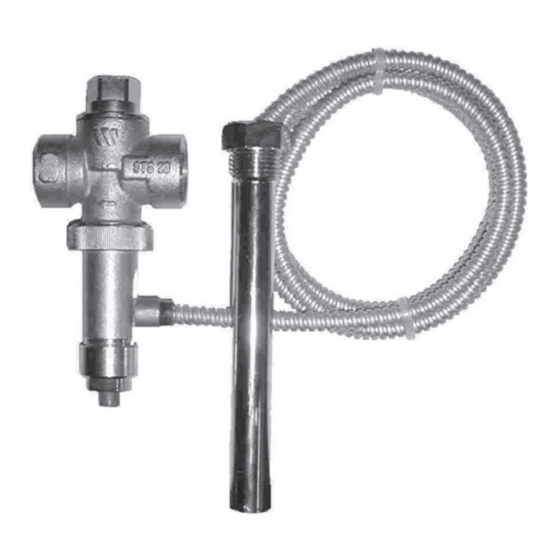
Die Ablaufsicherung Th Typ STS20 ist ein druckunabhängiges Ventil, das
durch die Vorlauftemperatur des Wärmeerzeugers bei Erreichen von 97°C
einen Wasserablauf am Brauchwasserwärmer öffnet und dadurch eine
Te m p e r a t u r s t e i g e r u n g ü b e r m a x i m a l 1 1 0 ° C ve r h i n d e r t .
Ausführung
Die thermische Ablaufsicherung ist gemäß DIN EN 14597 hergestellt.
Die verwendenten Werkstoffe entsprechen diesen Anforderungen.
Technische Daten
Min. Betriebstemperatur
Temperatur-Ansprechpunkt
Max. Betriebstemperatur
Betriebsüberdruck
Max. Leistung
Max. Leistung (1bar delta-p)
2,5 m
Hinweis
Nach DIN 1988 und AD-Merkblatt A3 bzw. 4753 ersetzt die thermische
Ablaufsicherung nicht das vorgeschriebene Membran-Sicherheitsventil.
Entsprechend der Vorschrift nach DIN EN 12170 ist der Betreiber der
Anlage verpflichtet, mindestens einmal jährlich die Ablaufsicherung durch
einen Fachmann auf Funktionstüchtigkeit überprüfen zu lassen.
Technische Eigenschaften
* Körper und Haube aus Pressmessing EN12165-99 CW617N
* Dichtung aus Viton
* Feder aus INOX-Stahl
* Druckknopf für manuellen Ablass aus rotem Kunstoff
* Kapillarrohr aus Kupfer, 1300 mm mit Schutzrohr
Wartung
Es ist notwendig den Ventilsitz von Ablagerungen und Schmutzpartikel zu
reinigen. Hierzu mehrmals den roten Druckknopf am Ventil betätigen, um
einen manuellen Ablass zu erzeugen.
Wenn das Ventil im geschlossenen Zustand undicht ist, Sitz und Kegel
wie folgt reinigen:
1. Sechskant (1) abschrauben u. Ventilkegel (2) entfernen.
2. Alle Teile sorgfältig mit Wasser reinigen, besonders Ventilsitz.
3. Teile wieder einführen u. Sechskant (1) gut anziehen.
Zubehör:
Ablauftrichter IS20 (3/4" x 1")
B
STS20
STS20/GX
STS20/85 STS20/55
(
1)
STS20/200
-10°C
-10°C
-10°C
97 ± 2°C
85 ± 3°C
55 ± 3°C
110°C
100°C
80°C
10 bar
10 bar
10 bar
6,5 m /h
6,5 m /h
3
3
6,5 m /h
3
/h
3
(1) Kapillarrohr 2000 mm lang.
DE
UK
IT
FR
PL
SK
HU
ES
CZ
Use
UK
The use of thermal relief valves is obligatory in all open tank systems using
solid, non-pulverized fuel fired boilers (R. 3.C.)
It prevents the temperature of the water inside boiler rising above boiling
point at standard atmospheric pressure.
Fitting
The thermal relief safety valve should be fitted proximate to the furnace
with the heat sensitive element submerged in the boiler water and the
valve body coupled to:
1. the hot sanitation water outlet pipework, for furnaces with boiler (A)
2. on the emergency heat exchanger inlet connexion for furnaces
devoid of boiler (B)
Ratings
STS20/103
-10°C
103 ± 3°C
Min. temperature
110°C
Set temperature (initial aperture)
10 bar
Maximum operating temperature
6,5 m /h
3
Maximum operating pressure
Max. discharge capacity
Max. discharge capacity
Dual Safety
The thermal relief valve type STS20 is furnished with 2 heat sensitive
elements; in the event of failure of one element, the other will assure that
the valve is operated.
Specifications
* Nickel plated, EN12165-99 CW617N brass construction body and bonnet.
* Viton seal and packing.
* Stainless steel spring.
* Manual discharge button in red resin.
* Copper capillary tube, lenght 1300 mm, with sheath.
Maintenance:
It's necessary to wash the valve seat in order to clean it from impurities
and deposits. To activate the manual discharge and therefore the cleaning,
press a few times the red button on the valve.
In the event of water leakage when the valve is shut, clean the valve seat
and the disk as follows:
1. Unscrew the bottom plug (1) and remove the disk (2) with the spring
inside it.
2. Clean, with water, the valve seat and remove any encrustations from
the seal.
3. Refit the spring inside the disk and introduce the assembly into the
bottom plug and screw to the valve body.
Accessories
Drain-off funnel IS20 (3/4" x 1)
STS20
STS20/103
STS20/85
STS20/55
STS20
STS20/GX
STS20/85 STS20/55
(
1)
STS20/200
-10°C
-10°C
97± 2°C
85 ± 3°C
110°C
100°C
10 bar
10 bar
6,5 m /h
6,5 m /h
3
(without back pressure)
2,5 m
/h
3
(1) Capillary tube lenght 2000 mm.
(with 1bar delta-p inlet outlet)
- 8FI/TS001AL
grafidea
STS20/103
-10°C
-10°C
55 ± 3°C
103 ± 3°C
80°C
110°C
10 bar
10 bar
6,5 m /h
3
6,5 m /h
3
3
Werbung

Verwandte Anleitungen für Watts STS20


Inhaltszusammenfassung für Watts STS20
- Seite 1 Dual Safety Nach DIN 1988 und AD-Merkblatt A3 bzw. 4753 ersetzt die thermische The thermal relief valve type STS20 is furnished with 2 heat sensitive Ablaufsicherung nicht das vorgeschriebene Membran-Sicherheitsventil. elements; in the event of failure of one element, the other will assure that Entsprechend der Vorschrift nach DIN EN 12170 ist der Betreiber der the valve is operated.
- Seite 2 Port. di scarico Max (1) Elemento sensibile da 2000 mm di lunghezza (con 1 bar delta-p ingresso uscita) La soupape thermique STS20 est munie de 2 éléments sensibles: en cas Doppia sicurezza d’avarie de l’un des deux, le deuxième assure également l’intervention Lo scarico di sicurezza termico STS20 è...
- Seite 3 Caudal máximo de descarga (1) Tube capiler de 2000 mm. Double seguridad El descargador térmico de seguridad STS20 está dotado de 2 elementos sensibles: en caso de avería de uno de los mismos, el segundo asegura igualmente la intervención de la válvula.