Inhaltsverzeichnis
Werbung
Verfügbare Sprachen
Verfügbare Sprachen
Quicklinks
BEDIENUNGSANWEISUNG
mit Montageanweisungen
INSTRUCTION FOR USE
and installation
D
GB
F
NL
I
E
P
VKM1820.0
Lesen Sie unbedingt die Gebrauchsanleitung
und den Montageplan vor Aufstellung,
Installation sowie Inbetriebnahme.
Please read the users an installation
instructions carefully before installation ot the
appliance and before starting to use.
Service und Kundendienst
Telefon: 0209 - 401 631
Email: kundendienst@kueppersbusch.de
240 920 0001 KC1
Werbung
Kapitel
Inhaltsverzeichnis

Verwandte Anleitungen für Küppersbusch VKM1820.0


Inhaltszusammenfassung für Küppersbusch VKM1820.0
- Seite 1 BEDIENUNGSANWEISUNG mit Montageanweisungen INSTRUCTION FOR USE and installation VKM1820.0 Lesen Sie unbedingt die Gebrauchsanleitung und den Montageplan vor Aufstellung, Installation sowie Inbetriebnahme. Please read the users an installation instructions carefully before installation ot the appliance and before starting to use.
-
Seite 2: Inhaltsverzeichnis
1 Allgemeines ..............3 1.1 Küppersbusch-Kundendienst ........3 1.2 Garantiebedingungen ..........4 1.3 Hier fi nden Sie............4 1.4 Bestimmungsgemäße Verwendung ......4 2 Sicherheitshinweise und Warnungen......5 2.1 Für Anschluss und Funktion ........5 2.2 Für Personen ............5 2.3 Symbol- und Hinweiserklärung ........6 3 Gerätebeschreibung ............7 4 Lüfter verwenden ............8 4.3.1 Lüfter ein- und ausschalten ........8 4.3.2 Lüfternachlauf ............8... -
Seite 3: Allgemeines
Allgemeines 1 Allgemeines Sie erreichen uns: Montag bis Freitag von 8:00 bis 17:00 Uhr 1.1 Küppersbusch-Kundendienst Außerhalb der Dienstzeiten teilen Sie uns Ihre Wünsche Zentrale Kundendienst- / Ersatzteilanforderung bitte per Telefax oder Internet unter Deutschland: www.kueppersbusch.at mit. Küppersbusch Hausgeräte GmbH Bitte beachten Sie: Küppersbuschstraße 16 Damit unser Kundendienst Reparaturen sorgfältig vorbe-... -
Seite 4: Garantiebedingungen
Allgemeines 1.2 Garantiebedingungen 4. In Fällen, in denen die Nachbesserung fehlschlägt oder von uns abgelehnt wird, liefern wir innerhalb der oben Zusätzlich zu seinen Gewährleistungsansprüchen aus genannten Garantiezeit auf Wunsch des Endabneh- seinem Kaufvertrag mit dem Händler leisten wir dem mers kostenfrei gleichwertigen Ersatz. -
Seite 5: Sicherheitshinweise Und Warnungen
Sicherheitshinweise und Warnungen 2 Sicherheitshinweise und Warnungen • Beim Kochen wird durch den Wrasen zusätz- lich Feuchtigkeit in die Raumluft abgegeben 2.1 Für Anschluss und Funktion • Im Umluftbetrieb wird die Feuchtigkeit aus • Die Geräte werden nach den einschlägigen dem Wrasen nur geringfügig entfernt. -
Seite 6: Symbol- Und Hinweiserklärung
Sicherheitshinweise und Warnungen 2.3 Symbol- und Hinweiserklärung Zusätzlich werden an einigen Stellen die folgenden Gefah- rensymbole verwendet: Das Gerät wurde nach aktuellem Stand der Technik gefer- tigt. Dennoch gehen von Maschinen Risiken aus, die sich konstruktiv nicht vermeiden lassen. WARNUNG VOR ELEKTRISCHER Um dem Bediener ausreichende Sicherheit zu gewähr- ENERGIE! leisten, werden zusätzlich Sicherheitshinweise gegeben,... -
Seite 7: Gerätebeschreibung
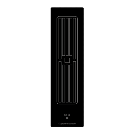
Gerätebeschreibung 3 Gerätebeschreibung Das Dekor kann von den Abbildungen abweichen. 1. Lüfter 2. Lüftesteuerung 3. Plus/Minus Taste Lüfter 4. Ein/ Aus Taste Lüfter... -
Seite 8: Lüfter Verwenden
Lüfter verwenden 4 Lüfter verwenden Wichtig: Abdeckung nicht auf dem Kochfeld ablegen! Verbrennungsgefahr! 4.3.1 Lüfter ein- und ausschalten 1. Ein-/Aus-Taste vom Lüfter betätigen (ca. 1 Sek.) 2. Anschließend kann durch die Plus- oder Minus-Taste eine gewünschte Leistungsstufe 1, 2, 3, 4 oder P gewählt werden. -
Seite 9: Hinweise Zur Nachlaufzeit
Lüfter verwenden Automatischen Nachlauf deaktivieren 4.3.4 Anzeige Fettfi lter reinigen 1. Die Steuerung über die Ein-/Aus-Taste vom Lüfter Nach 10 Betriebsstunden erscheint die Anzeige für Fil- einschalten. ter Cleaning. Der Fettfi lter muss gereinigt werden, ansons- ten besteht Brandgefahr. 2. Die Ein-/Aus-Taste vom Lüfter ca. -
Seite 10: Reinigung Und Pfl Ege
Reinigung und Pfl ege 5 Reinigung und Pfl ege Reinigung und Pfl ege des Lüfters Am besten reinigen Sie den Lüfter mindestens bei jeder Reinigung der Metallfettfi lter Filterreinigung. Reinigen Sie die Metallfettfi lter mindestens einmal im Nach intensivem Verkochen von Wasser mit geöff netem Monat oder bei Überfettung und intensiver Nutzung im Topfdeckel kann sich Kondenswasser unter dem Filter an- Geschirrspüler oder in milder Spüllauge. -
Seite 11: Zusammenbau Abluftsystem
Zusammenbau Abluftsystem 6 Zusammenbau Abluftsystem Abluftkanal-Komponenten oder Die Verbindung zwischen Kochfeld und Lüfter kann mit einem Flexschlauch oder einem Flachkanal erfolgen. oder Die Abluftkomponenten einer dieser beiden Varianten liegen dem Kochfeld bei und werden gemäß Abbildung ineinander gesteckt. Den Flachkanal nach Bedarf in der Länge mit einer Feinsäge kürzen. -
Seite 12: 6-Poliger Stecker Anschluss Lüfter
Zusammenbau Abluftsystem 6.1 6-poliger Stecker Anschluss Lüfter 6.2 Einbau Kochmulden Lüfter • Das Produkt darf nur von einem zugelassenen Fach- GEFAHR mann unter Beachtung der örtlich geltenden Vorschrif- Stromschlaggefahr ten angeschlossen werden, gleiches gilt für die Ab- Steckverbindung Lüfter muss vor dem Net- luftanschlüsse. -
Seite 13: Technische Daten
Technische Daten 8 Außerbetriebnahme, Entsorgung 7 Technische Daten 8.1 Außerbetriebnahme Abmessungen Wenn das Gerät eines Tages ausgedient hat, erfolgt die Höhe/ Breite/ Tiefe ..mm 174 x 140 x 520 Außerbetriebnahme. Lüfter ......kW 0,168 • Schalten Sie die Sicherung in der Hausinstallation aus, um Stromschlaggefahr zu vermeiden. -
Seite 14: General
General Contents 1 General 1.1 For your information... 1 General ................14 Please keep this manual in a safe place and pass it on to 1.1 For your information..........14 new owners for their information and safety. 1.2 Intended use ............14 2 Safety Instructions and Warnings ......15 1.2 Intended use 2.1 For connection and operation ........15... -
Seite 15: Safety Instructions And Warnings
Safety Instructions and Warnings 2 Safety Instructions and Warnings vapours in the convection air mode. This is why a suffi cient supply of fresh air must al- 2.1 For connection and operation ways be provided, e.g. by opening the window •... -
Seite 16: Explanation For Symbols And Indications
Safety Instructions and Warnings 2.3 Explanation for symbols and indications The following danger symbols are used at some points: The appliance was produced according to state of the art technology. Machines nevertheless give rise to risks which WARNING OF ELECTRICAL ENERGY cannot be constructively avoided. -
Seite 17: Appliance Description
Appliance description 3 Appliance description The decorative design may deviate from the illustrations. 1. Fan 2. Fan control 3. Plus key / Minus key fan 4. ON/OFF key fan... -
Seite 18: Using The Fan
Using the fan 4 Using the fan Important: Do not put the cover onto the hob! Risk of burning! 4.3.1 Switching the fan on and off 1. Press the fan ON/OFF key (approx. 1 s.) 2. You will then be able to select a power setting, 1,2,3 or 4, by using the Plus or Minus key . -
Seite 19: Notes On The After Run Time
Using the fan Disable automatic after-run 4.3.4 Display: Clean the grease fi lters 1. Turning on the control via the ON/OFF key on the fan After 10 hours of operation the display for fi lter clea- ning appears. The grease fi lter must be cleaned, otherwise there is a risk of fi... -
Seite 20: Cleaning And Care
Cleaning and care 5 Cleaning and care The fan is best cleaned every time you clean the fi lters. Condensation water may collect under the fi lter after water Cleaning the metal grease fi lters has boiled rapidly with the lid of the pot removed. This is Clean the metal grease fi... -
Seite 21: Extraction Air System Assembly
Extraction air system assembly 6 Extraction air system assembly Exhaust air duct components The hob and the fan can be connected with a fl exible hose or a fl at duct. The exhaust air components for on these two options are supplied with the hob and are fi... -
Seite 22: 6-Pole Fan Plug Connector
Extraction air system assembly 6.1 6-pole fan plug connector 6.2 Hob fan installation • The product may only be connected by a qualifi ed fi tter DANGER according to applicable local regulations. The same Risk of electric shocks applies for the extraction air connections. The fi tter is The fan plug connection must be made befo- responsible for proper functioning at the installation re the mains connection! -
Seite 23: Technical Data
Technical data 8 Decommissioning and disposal of the ap- 7 Technical data pliance Dimensions 8.1 Switching the appliance off completely height/ width/ depth ...mm 174 x 140 x 520 The appliance is to be put out of operation when its useful Fan ......kW 0.168 life has fi... -
Seite 24: Généralités
Généralités Sommaire 1 Généralités 1.1 Ce que vous trouverez ici... 1 Généralités ..............24 Conservez soigneusement cette notice. Remettez-la aux 1.1 Ce que vous trouverez ici........24 nouveaux propriétaires de l'appareil, pour leur sécurité et 1.2 Utilisation conforme ..........24 leur information. 2 Consignes de sécurité... -
Seite 25: Consignes De Sécurité Et Avertissements
Consignes de sécurité et avertissements 2 Consignes de sécurité et avertissements dité supplémentaire dans l'air ambiant. 2.1 Pour le raccordement et le fonctionnement • En mode « Recyclage d'air », cette humidité des vapeurs de cuisson n'est que très peu •... -
Seite 26: Explication Des Symboles Et Des Consignes
Consignes de sécurité et avertissements 2.3 Explication des symboles et des consignes En outre, les symboles de danger suivants marquent cer- tains passages de texte : L'appareil a été fabriqué selon l'état actuel de la technique. Cependant, les machines recèlent toujours des risques qu'il n'est pas possible d'exclure en matière de constructi- ATTENTION - ÉNERGIE ÉLECTRIQUE ! DANGER DE MORT ! -
Seite 27: Description De L'appareil
Description de l’appareil 3 Description de l’appareil Le décor peut être diff érent de celui illustré. 1. Ventilateur 2. Commande du ventilateur 3. Touche Plus/Moins du ventilateur 4. Touche Marche/Arrêt du ventilateur... -
Seite 28: Utiliser Le Ventilateur
Utiliser le ventilateur 4 Utiliser le ventilateur Important : Ne pas déposer le couvercle sur la table de cuisson ! Risque de brûlures ! 4.3.1 Mettre en marche et arrêter le ventilateur 1. Actionner la touche Marche/Arrêt du ventilateur (env. 1 sec.) 2. -
Seite 29: Conseils Concernant La Durée De La Temporisation D'arrêt
Utiliser le ventilateur Désactiver la temporisation d’arrêt automatique 4.3.4 Affi chage - Nettoyez les fi ltres à graisses 1. Activer la commande via la touche Marche/Arrêt du La mention , pour « Filter Cleaning », est affi chée au ventilateur bout de 10 heures de service. -
Seite 30: Nettoyage Et Entretien
Nettoyage et entretien 5 Nettoyage et entretien Il est recommandé de nettoyer le ventilateur au moins à chaque nettoyage de fi ltre. Nettoyage du fi ltre à graisses métallique Après une cuisson intensive avec de l'eau et des réci- Nettoyer au moins une fois par mois le fi ltre à graisses pients sans couvercle, de l'eau de condensation peut s'ac- métallique ou, en cas d'encrassement important et d'uti- cumuler sous le fi... -
Seite 31: Assemblage Du Système D'évacuation D'air
Assemblage du système d'évacuation d'air 6 Assemblage du système d'évacuation d'air Composants du canal d'évacuation Le raccordement de la table de cuisson au ventilateur peut se faire avec une gaine fl exible ou un canal plat. Les composants d'évacuation d'air de l'une de ces deux variantes sont fournies avec la table de cuisson et seront enfi... -
Seite 32: Connecteur 6 Pôles Pour Le Raccordement Du Ventilateur
Assemblage du système d'évacuation d'air 6.1 Connecteur 6 pôles pour le raccordement du 6.2 Ventilateur de table de cuisson ventilateur • Le produit doit être raccordé uniquement par un pro- fessionnel dans le respect des prescriptions locales en DANGER vigueur, ce qui vaut également pour les raccordements Risque d'électrocution ! d'évacuation. -
Seite 33: Caractéristiques Techniques
Caractéristiques techniques 8 Mise hors service, élimination 7 Caractéristiques techniques 8.1 Mise hors service Dimensions La mise hors service de l'appareil survient lorsque l'appa- hauteur/ largeur/ profondeur 174 x 140 x 520 reil n'est plus utilisé. Ventilateur ....kW 0,168 • Couper les fusibles de votre installation domestique afi... -
Seite 34: Algemene Opmerkingen
Algemene opmerkingen Inhoud 1 Algemene opmerkingen 1.1 Hier vindt u... 1 Algemene opmerkingen ..........34 Bewaar deze handleiding zorgvuldig. Geef deze gebruiks- 1.1 Hier vindt u.............34 en montagehandleiding ter informatie en veiligheid aan 1.2 Reglementair gebruik ..........34 een nieuwe eigenaar door. 2 Veiligheidsaanwijzingen en waarschuwingen ..35 2.1 Voor aansluiting en werking ........35 1.2 Reglementair gebruik... -
Seite 35: Veiligheidsaanwijzingen En Waarschuwingen
Veiligheidsaanwijzingen en waarschuwingen 2 Veiligheidsaanwijzingen en waarschuwin- • In circulatiebedrijf wordt het vocht uit de damp maar voor een klein deel verwijderd. Er moet daarom altijd voor voldoende toevoer van ver- 2.1 Voor aansluiting en werking se lucht, worden gezorgd, bijvoorbeeld door •... -
Seite 36: Symbool- En Instructieverklaring
Veiligheidsaanwijzingen en waarschuwingen 2.3 Symbool- en instructieverklaring Het apparaat werd volgens de huidige stand van de WAARSCHUWING VOOR ELEKTRI- techniek geproduceerd. Desondanks kunnen machines SCHE ENERGIE! risico's opleveren, die constructief niet te vermijden zijn. ER BESTAAT LEVENSGEVAAR! Om voldoende veiligheid voor de bediener te waarborgen, In de buurt van dit symbool zijn onder worden extra veiligheidsinstructies gegeven in de vorm spanning staande onderdelen aangebracht. -
Seite 37: Beschrijving Van Het Toestel
Beschrijving van het toestel 3 Beschrijving van het toestel Het decor kan van de afbeeldingen afwijken. 1. Ventilator 2. Ventilatoraansturing 3. Plus-min-toets van de ventilator 4. Aan/Uit-toets van de ventilator... -
Seite 38: Ventilator Gebruiken
Ventilator gebruiken 4 Ventilator gebruiken Belangrijk: Leg het deksel niet op de kookplaat! Gevaar voor verbranding! 4.3.1 Ventilator in- en uitschakelen 1. Aan/Uit-toets van de ventilator indrukken (ca. 1 sec.) 2. Daarna kan met de plus- / of min-toets een gewenste vermogensstand 1, 2, 3 of 4 worden gekozen. -
Seite 39: Aanwijzingen M.b.t. De Nalooptijd
Ventilator gebruiken Automatische naloop deactiveren Na 10 bedrijfsuren verschijnt de indicatie voor ‘Filter Cleaning’. De vetfi lter moet gereinigd worden, anders 1. De besturing met de Aan/Uit-toets van de ventilator bestaat er brandgevaar. inschakelen. 2. De Aan/Uit-toets van de ventilator ca. -
Seite 40: Reiniging En Onderhoud
Reiniging en onderhoud 5 Reiniging en onderhoud Het geniet de voorkeur om de ventilator bij iedere fi lterrei- niging te reinigen. Reiniging van de metalen vetfi lters Na langdurige koken van water met geopend deksel kan Reinig de metalen vetfi lters minimaal één keer per maand zich condenswater onder het fi... -
Seite 41: Montage Afzuigsysteem
Montage afzuigsysteem 6 Montage afzuigsysteem Componenten afzuigkanaal De verbinding tussen kookplaat en ventilator kan met een fl exibele slang of een plat kanaal tot stand worden ge- bracht. De afzuigcomponenten van een van deze twee varianten is bij de kookplaat bijgevoegd en deze worden overeen- komstig de afbeelding in elkaar gestoken Het platte kanaal indien nodig met een fi... -
Seite 42: 6-Polige Stekker Aansluiting Ventilator
Montage afzuigsysteem 6.1 6-polige stekker aansluiting ventilator 6.2 Montage kookplaatventilator • Het product mag alleen door een erkende vakman met GEVAAR inachtneming van de plaatselijk geldende voorschriften Gevaar voor elektrische schokken worden aangesloten; hetzelfde geldt voor de afzui- De stekker van de ventilator moet voor de gingsaansluitingen. -
Seite 43: Technische Gegevens
Technische gegevens 8 Buitenbedrijfstelling, afvoer 7 Technische gegevens 8.1 Buitenbedrijfstelling Afmetingen Als het apparaat ooit is uitgediend, vindt de buitenbedri- hoogte/ breedte/ diepte mm 174 x 140 x 520 jfstelling plaats. Ventilator ....kW 0,168 • Schakel de zekering in de huisinstallatie uit om het risico op elektrische schokken uit te sluiten. -
Seite 44: Linee Generali
Linee generali Contenuto 1 Linee generali 1.1 Qui trovate... 1 Linee generali .............44 Conservare questo manuale per un’eventuale consulta- 1.1 Qui trovate.............44 zione futura Consegnarlo ai nuovi eventuali proprietari 1.2 Utilizzo conforme alla destinazione d’uso .....44 per loro opportuna informazione e per la tutela della loro incolumità. -
Seite 45: Indicazioni In Materia Di Sicurezza E Avvertenze
Indicazioni in materia di sicurezza e avvertenze 2 Indicazioni in materia di sicurezza e avver- grasso viene rimossa soltanto in piccola tenze parte. Occorre pertanto provvedere sempre a un suffi ciente apporto di aria fresca, per es. 2.1 Per il collegamento e il funzionamento lasciando una fi... -
Seite 46: Spiegazione Dei Simboli E Delle Avvertenze
Indicazioni in materia di sicurezza e avvertenze 2.3 Spiegazione dei simboli e delle avvertenze L'apparecchio è stato costruito secondo lo stato attuale ATTENZIONE! ENERGIA ELETTRICA! della tecnica. Le macchine comportano tuttavia dei rischi PERICOLO DI MORTE! che non sono evitabili sotto il profi lo costruttivo. Questo simbolo mette in guardia dalle parti Per garantire all’operatore una sicurezza suffi... -
Seite 47: Descrizione Dell'apparecchio
Descrizione dell'apparecchio 3 Descrizione dell'apparecchio La decorazione del piano può diff erire dalle illustrazioni. 1. Ventilatore 2. Comando del ventilatore 3. Tasto Più / Meno del ventilatore 4. Tasto di accensione/spegnimento del ventilatore... -
Seite 48: Usare La Cappa Aspirante
Usare la cappa aspirante 4 Usare la cappa aspirante Importante! Non mettere la copertura sul piano cottura! Pericolo di ustionarsi! 4.3.1 Accensione e spegnimento del ventilatore 1. Premere il tasto di accensione/ spegnimento per 1 s. circa. 2. Usare adesso i tasti Più o Meno per scegliere il livello di potenza desiderato 1, 2, 3 o 4 del ventilatore. -
Seite 49: Indicazioni Per Il Tempo Di Alimentazione Successiva
Usare la cappa aspirante Disattivare il tempo di alimentazione successiva auto- 4.3.4 Indicazione - Pulire il fi ltro per grassi matico Dopo 10 ore di funzionamento, appare sul display l’indi- 1. Accendere il controllo del ventilatore con il tasto di cazione per la pulizia del fi... -
Seite 50: Pulizia E Manutenzione
Pulizia e manutenzione 5 Pulizia e manutenzione Dopo la cottura intensa di acqua senza aver coperto la pentola è possibile che l'acqua condensata si accumuli Pulizia dei fi ltri antigrasso metallici sotto il fi ltro. Questo è del tutto normale. Però si deve eli- Pulire i fi... -
Seite 51: Assemblaggio Del Sistema Di Scarica Dell'aria
Assemblaggio del sistema di scarica dell'aria 6 Assemblaggio del sistema di scarica de- Componenti del canale di scarica ll'aria oppure La giunzione tra ventilatore e piano di cottura può essere oppure eseguita con un tubo fl essibile o un canale piatto. I componenti di scarica di una delle varianti sono allegati al piano di cottura e devono essere inseriti come illustrato. -
Seite 52: Connettore A 6 Poli Per L'allacciamento Al Ventilatore
Assemblaggio del sistema di scarica dell'aria 6.1 Connettore a 6 poli per l'allacciamento al 6.2 Incasso del sistema di ventilazione ventilatore • L'allacciamento alle rete elettrica e il collegamento degli allacciamento per l'aria di scarica del prodotto può PERICOLO essere eseguito solo da un tecnico specializzato e abili- Lesione da corrente elettrica tato e in base alle norme in materia valide! L'installatore Collegare il ventilatore prima dell'allaccia-... -
Seite 53: Dati Tecnici
Dati tecnici 8 Messa fuori servizio, smaltimento 7 Dati tecnici 8.1 Mettere fuori servizio Dimensioni del piano di Quando l'apparecchio un giorno cessa il suo servizio gior- cottura 174 x 140 x 520 naliero, avviene la sua messa fuori servizio. Altezza /larghezza /profon- •... -
Seite 54: Generalidades
Generalidades Índice 1 Generalidades 1.1 Aquí encontrará usted... 1 Generalidades ............54 Conserve estas instrucciones cuidadosamente. Entregue 1.1 Aquí encontrará usted..........54 estas instrucciones de uso y de montaje a los nuevos 1.2 Uso previsto ............54 propietarios para su información y seguridad. 2 Indicaciones de seguridad y advertencias .....55 1.2 Uso previsto 2.1 Conexión y funcionamiento ........55... -
Seite 55: Indicaciones De Seguridad Y Advertencias
Indicaciones de seguridad y advertencias 2 Indicaciones de seguridad y advertencias se carga más de humedad. 2.1 Conexión y funcionamiento • En el modo de circulación de aire, la hume- dad es eliminada del vapor sólo en una me- • Los aparatos hay que montarlos siguiendo las dida muy reducida. -
Seite 56: Explicación De Los Símbolos Y De Las Indicaciones
Indicaciones de seguridad y advertencias 2.3 Explicación de los símbolos y de las indicaci- Además, en algunos lugares se emplean los siguientes ones símbolos de peligro: El aparato ha sido fabricado conforme al nivel de desar- rollo actual de la técnica. Aún así, de las máquinas se de- ¡ADVERTENCIA DE ENERGÍA ELÉCTRI- rivan ciertos riesgos que no es posible evitar con medidas constructivas. -
Seite 57: Descripción Del Aparato
Descripción del aparato 3 Descripción del aparato La decoración puede diferir de la representada en las fi guras. 1. Ventilador 2. Control del ventilador 3. Tecla Más/Menos del ventilador 4. Tecla de encendido / apagado del ventilador... -
Seite 58: Uso Del Ventilador
Uso del ventilador 4 Uso del ventilador Importante: ¡No depositar la cubierta sobre la encimera! ¡Peligro de quemaduras! 4.3.1 Conexión y desconexión del ventilador 1. Pulsar la tecla de encendido / apagado del ventilador (aprox. 1 segundo) 2. Seguidamente, pulsando la tecla más o menos posible seleccionar el nivel de potencia deseado 1, 2, 3, 4 o P. -
Seite 59: Indicaciones Relativas Al Tiempo De Funcionamiento Suplementario
Uso del ventilador Desactivación del funcionamiento suplementario Con el modo de recirculación de aire hay que tomar las automático medidas oportunas para que haya una entrada y salida de aire sufi cientes de manera que pueda ser evacuada la 1. Conectar el control con la tecla de encendido/apagado humedad. -
Seite 60: Limpieza Y Conservación
Limpieza y conservación 5 Limpieza y conservación Limpieza y cuidados del ventilador La mejor opción es limpiar el ventilador tras cada limpieza Limpieza de los fi ltros de grasa de metal de los fi ltros. Limpie los fi ltros de grasa de metal en el lavavajillas o en Tras una cocción intensiva de agua con la tapa de la olla agua jabonosa suave como mínimo una vez al mes o en abierta puede acumularse agua condensada debajo del... -
Seite 61: Montaje Del Sistema De Extracción De Aire
Montaje del sistema de extracción de aire 6 Montaje del sistema de extracción de aire Componentes del canal de aire de escape o bien La conexión entre la encimera y el ventilador puede reali- zarse con un tubo fl exible o con un canal plano. o bien Los componentes para el escape del aire de una de estas dos variantes se adjuntan con la encimera y se empalman... -
Seite 62: Conector De 6 Polos Conexión Ventilador
Montaje del sistema de extracción de aire 6.1 Conector de 6 polos conexión ventilador 6.2 Montaje del ventilador de encimera • El producto tiene que ser conectado obligatoriamente PELIGRO por un profesional autorizado observando las normas Riesgo de electrocución vigentes localmente; lo mismo vale para las conexiones ¡La conexión del ventilador tiene que tener de aire de escape. -
Seite 63: Datos Técnicos
Datos técnicos 8 Puesta fuera de servicio, eliminación 7 Datos técnicos 8.1 Puesta fuera de servicio Dimensiones La puesta fuera de servicio tiene lugar una vez concluido Alto/ Ancho/ Largo ..mm 174 x 140 x 520 el periodo de vida del aparato. Ventilador ....kW 0,168 •... -
Seite 64: Aspetos Gerais
Aspetos gerais Índice 1 Aspetos gerais 1.1 Aqui você encontra... 1 Aspetos gerais ............64 Guarde cuidadosamente este manual. Por favor entregue 1.1 Aqui você encontra..........64 estas instruções de uso e instalação a proprietários novos 1.2 Utilização conforme as determinações ....64 para a informação e segurança dos mesmos. -
Seite 65: Indicações De Segurança E Avisos
Indicações de segurança e avisos 2 Indicações de segurança e avisos mais humidade ao ar ambiente. 2.1 Ligação e funcionamento • No funcionamento com recirculação, a humi- dade só é retirada minimamente aos vapores. • Os aparelhos são construídos de acordo com Por isso, é... -
Seite 66: Explicação De Símbolos E Indicações
Indicações de segurança e avisos 2.3 Explicação de símbolos e indicações seguintes símbolos de perigo: O aparelho foi fabricado segundo o estado atual da técnica. No entanto, as máquinas implicam riscos que não AVISO DE ENERGIA ELÉTRICA! podem ser evitados com a construção. EXISTE PERIGO DE VIDA! Para garantir uma segurança sufi... -
Seite 67: Descrição Do Aparelho
Descrição do aparelho 3 Descrição do aparelho A aparência pode divergir das ilustrações. 1. Ventilador 2. Controlo do ventilador 3. Tecla Mais / Menos do ventilador 4. Tecla LIG/DESL do ventilador... -
Seite 68: Usar O Ventilador
Usar o ventilador 4 Usar o ventilador Importante! Não colocar a cobertura sobre a placa de cozinhar! Risco de queimaduras! 4.3.1 Ligar e desligar o ventilador 1. Acione a tecla de Ligar/Desligar do ventilador (aprox. 1 seg.) 2. A seguir pode ser escolhido o nível de potência desejado 1, 2, 3, 4 ou P com a tecla Mais ou a tecla Menos O símbolo do ventilador... -
Seite 69: Notas Sobre A Marcha Posterior
Usar o ventilador Desativar a marcha posterior automática Após 10 horas de funcionamento, aparece o ecrã de Filter Cleaning (limpeza do fi ltro) . O fi ltro de gorduras deve 1. Ligue o comando através a tecla LIG/DESL do ventil- ser limpo, caso contrário existe o risco de incêndio. -
Seite 70: Limpeza E Conservação
Limpeza e conservação 5 Limpeza e conservação O melhor é limpar o ventilador pelo menos após cada limpeza do fi ltro. Limpeza dos fi ltros de gordura metálicos Após uma fervura intensa de água com a tampa da panela Limpe os fi ltros de gordura metálicos, pelo menos uma aberta pode acumular-se água condensada por baixo do vez por mês ou no caso de excesso de gordura e uti- fi... -
Seite 71: Montagem Do Sistema De Exaustão
Montagem do sistema de exaustão 6 Montagem do sistema de exaustão Componentes do canal de exaustão A ligação entre a placa de cozinhar e o ventilador pode ser realizada com um tubo fl exível ou um canal chato. Os componentes de exaustão de uma destas duas varian- tes estão incluídos na placa de cozinhar e são encaixados uns nos outros conforme é... -
Seite 72: Conector De 6 Polos Para A Ligação Do Ventilador
Montagem do sistema de exaustão 6.1 Conector de 6 polos para a ligação do ventil- 6.2 Instalação do ventilador da placa de cozinhar ador • O produto só pode ser conectado por um técnico autorizado sob consideração dos regulamentos locais PERIGO vigentes;... -
Seite 73: Características Técnicas
Características técnicas 8 Colocação fora de serviço, eliminação 7 Características técnicas 8.1 Colocação fora de serviço Medidas Quando o aparelho, um dia, deixar de trabalhar, é neces- Altura/ largura/ profundidade 174 x 140 x 520 sário proceder à colocação fora do serviço. Ventilador ...... - Seite 74 Características técnicas...
- Seite 75 Características técnicas...