Inhaltsverzeichnis
Werbung
Verfügbare Sprachen
Verfügbare Sprachen
Quicklinks
Version 1.1
Published September 2015
Copyright©2015 ASRock INC. All rights reserved.
Copyright Notice:
No part of this documentation may be reproduced, transcribed, transmitted, or
translated in any language, in any form or by any means, except duplication of
documentation by the purchaser for backup purpose, without written consent of
ASRock Inc.
Products and corporate names appearing in this documentation may or may not
be registered trademarks or copyrights of their respective companies, and are used
only for identiication or explanation and to the owners' beneit, without intent to
infringe.
Disclaimer:
Speciications and information contained in this documentation are furnished for
informational use only and subject to change without notice, and should not be
constructed as a commitment by ASRock. ASRock assumes no responsibility for
any errors or omissions that may appear in this documentation.
With respect to the contents of this documentation, ASRock does not provide
warranty of any kind, either expressed or implied, including but not limited to
the implied warranties or conditions of merchantability or itness for a particular
purpose.
In no event shall ASRock, its directors, oicers, employees, or agents be liable for
any indirect, special, incidental, or consequential damages (including damages for
loss of proits, loss of business, loss of data, interruption of business and the like),
even if ASRock has been advised of the possibility of such damages arising from any
defect or error in the documentation or product.
his device complies with Part 15 of the FCC Rules. Operation is subject to the following
two conditions:
(1) this device may not cause harmful interference, and
(2) this device must accept any interference received, including interference that
may cause undesired operation.
CALIFORNIA, USA ONLY
he Lithium battery adopted on this motherboard contains Perchlorate, a toxic substance
controlled in Perchlorate Best Management Practices (BMP) regulations passed by the
California Legislature. When you discard the Lithium battery in California, USA, please
follow the related regulations in advance.
"Perchlorate Material-special handling may apply, see www.dtsc.ca.gov/hazardouswaste/
perchlorate"
ASRock Website: http://www.asrock.com
Downloaded from
www.Manualslib.com
manuals search engine
Werbung
Inhaltsverzeichnis

Verwandte Anleitungen für ASROCK H110M Combo-G


Inhaltszusammenfassung für ASROCK H110M Combo-G
- Seite 1 (including damages for loss of proits, loss of business, loss of data, interruption of business and the like), even if ASRock has been advised of the possibility of such damages arising from any defect or error in the documentation or product.
- Seite 2 he terms HDMI™ and HDMI High-Deinition Multimedia Interface, and the HDMI logo are trademarks or registered trademarks of HDMI Licensing LLC in the United States and other countries. Downloaded from www.Manualslib.com manuals search engine...
-
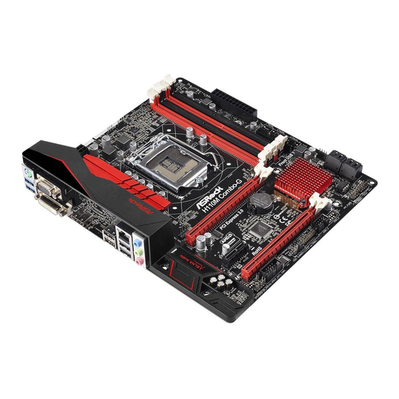
Seite 3: Motherboard-Layout
H110M Combo-G Motherboard Layout CPU_FAN1 ATX12V1 USB 2.0 T: USB5 B: USB6 USB 2.0 Top: T: USB7 RJ-45 B: USB8 H110M Combo-G CHA_FAN2 Front USB 3.0 PCIE1 PCI Express 3.0 CMOS Battery Intel PCIE2 H110 RoHS PCIE3 BIOS SPK_PLED PANEL1... - Seite 4 No. Description ATX 12V Power Connector (ATX12V1) CPU Fan Connector (CPU_FAN1) 2 x 288-pin DDR4 DIMM Slots (DDR4_A1, DDR4_B1) 2 x 240-pin DDR3/DDR3L DIMM Slots (DDR3_A1, DDR3_B1) ATX Power Connector (ATXPWR1) USB 3.0 Header (USB3_1_2) USB 2.0 Header (USB9_10) Chassis Fan Connector (CHA_FAN1) SATA3 Connector (SATA3_2) SATA3 Connector (SATA3_3) SATA3 Connector (SATA3_1)
- Seite 5 H110M Combo-G I/O Panel No. Description No. Description PS/2 Mouse/Keyboard Port USB 2.0 Ports (USB78) D-Sub Port USB 2.0 Ports (USB56) LAN RJ-45 Port* HDMI Port Line In (Light Blue)** DVI-D Port Front Speaker (Lime)** USB 3.0 Ports (USB3_34) Microphone (Pink)** * here are two LEDs on each LAN port.
- Seite 6 ** To conigure 7.1 CH HD Audio, it is required to use an HD front panel audio module and enable the multi- channel audio feature through the audio driver. Please set Speaker Coniguration to “7.1 Speaker”in the Realtek HD Audio Manager. Function of the Audio Ports in 7.1-channel Coniguration: Port Function...
-
Seite 7: Chapter 1 Introduction
If you require technical support related to this mother- board, please visit our website for speciic information about the model you are using. You may ind the latest VGA cards and CPU support list on ASRock’s website as well. ASRock website http://www.asrock.com. - Seite 8 1.2 Speciications • Micro ATX Form Factor Platform • Solid Capacitor design • Supports 6 Generation Intel® Core i7/i5/i3/Pentium®/ Celeron® Processors (Socket 1151) • Digi Power design • 6 Power Phase design • Supports Intel® Turbo Boost 2.0 Technology • Intel® H110 Chipset • Dual Channel DDR4/DDR3/DDR3L Memory Technology Memory...
- Seite 9 * To conigure 7.1 CH HD Audio, it is required to use an HD front panel audio module and enable the multi-channel audio feature through the audio driver. • Supports Surge Protection (ASRock Full Spike Protection) • ELNA Audio Caps • Gigabit LAN 10/100/1000 Mb/s • Giga PHY Intel®...
- Seite 10 • 1 x D-Sub Port • 1 x DVI-D Port • 1 x HDMI Port • 4 x USB 2.0 Ports (Supports ESD Protection (ASRock Full Spike Protection)) • 2 x USB 3.0 Ports (Supports ESD Protection (ASRock Full Spike Protection)) • 1 x RJ-45 LAN Port with LED (ACT/LINK LED and SPEED...
- Seite 11 * To install Windows® 7 OS, a modiied installation disk with xHCI drivers packed into the ISO ile is required. Please refer to page 138 for more detailed instructions. * For the updated Windows® 10 driver, please visit ASRock’s website for details: http://www.asrock.com • FCC, CE, WHQL Certiica- • ErP/EuP ready (ErP/EuP ready power supply is required)
-
Seite 12: Chapter 2 Installation
Chapter 2 Installation his is a Micro ATX form factor motherboard. Before you install the motherboard, study the coniguration of your chassis to ensure that the motherboard its into it. Pre-installation Precautions Take note of the following precautions before you install motherboard components or change any motherboard settings. -
Seite 13: Installing The Cpu
H110M Combo-G 2.1 Installing the CPU 1. Before you insert the 1151-Pin CPU into the socket, please check if the PnP cap is on the socket, if the CPU surface is unclean, or if there are any bent pins in the socket. Do not force to insert the CPU into the socket if above situation is found. - Seite 14 Downloaded from www.Manualslib.com manuals search engine...
- Seite 15 H110M Combo-G Please save and replace the cover if the processor is removed. he cover must be placed if you wish to return the motherboard for ater service. Downloaded from www.Manualslib.com manuals search engine...
- Seite 16 2.2 Installing the CPU Fan and Heatsink Downloaded from www.Manualslib.com manuals search engine...
- Seite 17 H110M Combo-G 2.3 Installing Memory Modules (DIMM) his motherboard provides two 288-pin DDR4 (Double Data Rate 4) and two 240- pin DDR3/DDR3L (Double Data Rate 3) DIMM slots, and supports Dual Channel Memory Technology. Warning! It is NOT allowed to install a memory module into a DDR4 slot and a DDR3 slot simultaneously;...
- Seite 18 Downloaded from www.Manualslib.com manuals search engine...
- Seite 19 H110M Combo-G 2.4 Expansion Slots (PCI Express Slots) here are 3 PCI Express slots on the motherboard. Before installing an expansion card, please make sure that the power supply is switched of or the power cord is unplugged. Please read the documentation of the expansion card and make necessary hardware settings for the card before you start the installation.
- Seite 20 2.5 Jumpers Setup he illustration shows how jumpers are setup. When the jumper cap is placed on the pins, the jumper is “Short”. If no jumper cap is placed on the pins, the jumper is “Open”. he illustration shows a 3-pin jumper whose pin1 and pin2 are “Short” when a jumper cap is placed on these 2 pins.
- Seite 21 H110M Combo-G 2.6 Onboard Headers and Connectors Onboard headers and connectors are NOT jumpers. Do NOT place jumper caps over these headers and connectors. Placing jumper caps over the headers and connectors will cause permanent damage to the motherboard. System Panel Header...
- Seite 22 SPEAKER Power LED and Speaker Please connect the DUMMY Header power LED and the DUMMY (7-pin SPK_PLED) chassis speaker to this (see p.1, No. 14) header. PLED+ PLED+ PLED- Serial ATA3 Connectors hese four SATA3 (SATA3_0) connectors support SATA (see p.1, No. 11) data cables for internal (SATA3_1) storage devices with up to...
- Seite 23 H110M Combo-G Front Panel Audio Header his header is for PRESENCE# MIC_RET (9-pin HD_AUDIO1) connecting audio devices OUT_RET (see p.1, No. 20) to the front audio panel. OUT2_L J_SENSE OUT2_R MIC2_R MIC2_L 1. High Deinition Audio supports Jack Sensing, but the panel wire on the chassis must sup- port HDA to function correctly.
- Seite 24 ATX Power Connector his motherboard pro- (24-pin ATXPWR1) vides a 24-pin ATX power (see p.1, No. 5) connector. To use a 20-pin ATX power supply, please plug it along Pin 1 and Pin ATX 12V Power his motherboard pro- Connector vides a 8-pin ATX 12V (8-pin ATX12V1) power connector.
- Seite 25 H110M Combo-G 1 Einleitung Vielen Dank, dass Sie sich für das H110M Combo-G von ASRock entschieden haben – ein zuverlässiges Motherboard, das konsequent unter der strengen Qualitätskontrolle von ASRock hergestellt wurde. Es liefert ausgezeichnete Leistung mit robustem Design, das ASRock Streben nach Qualität und Beständigkeit erfüllt.
-
Seite 26: Technische Daten
1.2 Technische Daten • Micro-ATX-Formfaktor Plattform • Feststokondensator-Design • Unterstützt die Prozessoren Intel® Core Prozessor i7/i5/i3/Pentium®/ Celeron® der 6. Generation (Sockel 1151) • Digi Power design • 6-Leistungsphasendesign • Unterstützt Intel® Turbo Boost 2.0-Technologie • Intel® H110 Chipsatz • Dualkanal-DDR4/DDR3/DDR3L-Speichertechnologie Speicher • 2 x DDR4-DIMM-Steckplätze • Unterstützt DDR4 2133 non-ECC, ungepuferter Speicher... - Seite 27 • 7.1-Kanal-HD-Audio (Realtek ALC887-Audiocodec) Audio *Zur Koniguration von 7.1-Kanal-HD-Audio müssen Sie ein HD- Frontblenden-Audiomodul nutzen und den Mehrkanalton über den Audiotreiber aktivieren. • Unterstützt Überspannungsschutz (ASRock Full Spike Protection) • ELNA-Audiokondensatoren • Gigabit LAN 10/100/1000 Mb/s • Giga PHY Intel® I219V • Unterstützt Wake-On-LAN...
- Seite 28 • 1 x DVI-D-Port • 1 x HDMI-Port • 4 x USB 2.0-Ports (unterstützt Schutz gegen elektrostatische Entladung (ASRock Full Spike Protection)) • 2 x USB 3.0-Ports (unterstützt Schutz gegen elektrostatische Entladung (ASRock Full Spike Protection)) • 1 x RJ-45-LAN-Port mit LED (Aktivität/Verbindung-LED und Geschwindigkeit-LED) • HD-Audioanschlüsse: Line-in / Vorderer Lautsprecher /...
- Seite 29 • ErP/EuP ready (ErP/EuP ready-Netzteil erforderlich) zierungen * Detaillierte Produktinformationen inden Sie auf unserer Webseite: http://www.asrock.com Bitte beachten Sie, dass mit einer Übertaktung, zu der die Anpassung von BIOS-Einstellungen, die Anwendung der Untied Overclocking Technology oder die Nutzung von Übertaktung- swerkzeugen von Drittanbietern zählen, bestimmte Risiken verbunden sind.
-
Seite 30: Jumpereinstellung
1.3 Jumpereinstellung Die Abbildung zeigt, wie die Jumper eingestellt werden. Wenn die Jumper-Kappe auf den Kontakten angebracht ist, ist der Jumper „kurzgeschlossen“. Wenn keine Jumper- Kappe auf den Kontakten angebracht ist, ist der Jumper „ofen“. Die Abbildung zeigt einen 3-poligen Jumper, dessen Kontakt 1 und Kontakt 2 „kurzgeschlossen“ sind, wenn eine Jumper-Kappe auf diesen 2 Kontakten angebracht ist. -
Seite 31: Integrierte Stiftleisten Und Anschlüsse
H110M Combo-G 1.4 Integrierte Stiftleisten und Anschlüsse Integrierte Stitleisten und Anschlüsse sind KEINE Jumper. Bringen Sie KEINE Jumper-Kappen an diesen Stitleisten und Anschlüssen an. Durch Anbringen von Jumper-Kappen an diesen Stitleisten und Anschlüssen können Sie das Motherboard dauerhat beschädigen. Systemblende-Stitleiste... - Seite 32 SPEAKER Betrieb-LED- und Bitte verbinden Sie DUMMY Lautsprecher-Stitleiste Betrieb-LED und DUMMY (7-polig, SPK_PLED) Gehäuselautsprecher mit (siehe S. 1, Nr. 14) dieser Stitleiste. PLED+ PLED+ PLED- Serial-ATA-III-Anschlüsse Diese vier SATA-III- (SATA3_0) Anschlüsse unterstützen (siehe S. 1, Nr. 11) SATA-Datenkabel für (SATA3_1) interne Speichergeräte mit (siehe S.
- Seite 33 H110M Combo-G Audiostitleiste Diese Stitleiste dient PRESENCE# MIC_RET (Frontblende) dem Anschließen von OUT_RET (9-polig, HD_AUDIO1) Audiogeräten an der (siehe S. 1, Nr. 20) Frontblende. OUT2_L J_SENSE OUT2_R MIC2_R MIC2_L 1. High Deinition Audio unterstützt Anschlusserkennung, der Draht am Gehäuse muss dazu jedoch HDA unterstützt.
- Seite 34 ATX-Netzanschluss Dieses Motherboard (24-polig, ATXPWR1) bietet einen 24-poligen (siehe S. 1, Nr. 5) ATX-Netzanschluss. Bitte schließen Sie es zur Nutzung eines 20-poligen ATX-Netzteils entlang Kontakt 1 und Kontakt 13 an. ATX-12-V-Netzanschluss Dieses Motherboard bietet (8-polig, ATX12V1) einen 8-poligen ATX- (siehe S. 1, Nr. 1) 12-V-Netzanschluss.
-
Seite 35: Contenu De L'emballage
Si vous avez besoin d’une assistance technique pour votre carte mère, veuillez visiter notre site Internet pour plus de détails sur le modèle que vous utilisez. La liste la plus récente des cartes VGA et des processeurs pris en charge est également disponible sur le site Internet de ASRock. Site Internet ASRock http://www.asrock.com. - Seite 36 1.2 Spéciications • Facteur de forme Micro ATX Plateforme • Conception à condensateurs solides • Prend en charge les processeurs 6 Processeur génération Intel® Core i7/i5/i3/Pentium®/Celeron® (Socket 1151) • Digi Power design • Alimentation à 6 phases • Prend en charge la technologie Intel® Turbo Boost 2.0 • Intel®...
- Seite 37 • Giga PHY Intel® I219V • Prend en charge la fonction Wake-On-LAN • Protection contre les orages/décharges électrostatiques (Protection complète contre les pics ASRock) • Prend en charge la fonction d’ é conomie d’ é nergie Ethernet 802.3az • Prend en charge PXE Downloaded from www.Manualslib.com...
- Seite 38 • 2 x embases USB 2.0 (4 ports USB 2.0 pris en charge) (Protection contre les décharges électrostatiques (Protection complète contre les pics ASRock)) • 1 x embase USB 3.0 (2 ports USB 3.0 pris en charge) (Protection contre les décharges électrostatiques (Protection complète contre les pics ASRock))
- Seite 39 Certiications • ErP/EuP Ready (alimentation ErP/EuP ready requise) * pour des informations détaillées de nos produits, veuillez visiter notre site : http://www.asrock.com Il est important de signaler que l’ o vercloking présente certains risques, incluant des modiica- tions du BIOS, l’ a pplication d’une technologie d’ o verclocking déliée et l’utilisation d’ o utils d’...
- Seite 40 1.3 Coniguration des cavaliers (jumpers) L’illustration ci-dessous vous renseigne sur la coniguration des cavaliers (jumpers). Lorsque le capuchon du cavalier est installé sur les broches, le cavalier est « court- circuité ». Si le capuchon du cavalier n’ e st pas installé sur les broches, le cavalier est « ouvert ».
- Seite 41 H110M Combo-G 1.4 Embases et connecteurs de la carte mère Les embases et connecteurs situés sur la carte NE SONT PAS des cavaliers. Ne placez JAMAIS de capuchons de cavaliers sur ces embases ou connecteurs. Placer un capuchon de cavalier sur ces embases ou connecteurs endommagera irrémédiablement votre carte mère.
- Seite 42 SPEAKER Prise DEL d’alimentation Veuillez connecter le LED DUMMY et haut-parleur d’alimentation et le et le DUMMY (SPK_PLED à 7 broches) haut-parleur du châssis sur (voir p.1, No. 14) ce connecteur. PLED+ PLED+ PLED- Connecteurs Serial ATA3 Ces quatre connecteurs (SATA3_0) SATA3 sont compatibles (voir p.1, No.
- Seite 43 H110M Combo-G Embase audio du panneau Cette embase sert au PRESENCE# MIC_RET frontal branchement des appareils OUT_RET (HD_AUDIO1 à 9 audio au panneau audio broches) frontal. OUT2_L (voir p.1, No. 20) J_SENSE OUT2_R MIC2_R MIC2_L 1. L’ a udio haute déinition prend en charge la technologie Jack Sensing (détection de la iche), mais le panneau grillagé...
- Seite 44 Connecteur d’alimentation Cette carte mère est dotée d’un connecteur (ATXPWR1 à 24 broches) d’alimentation ATX à 24 (voir p.1, No. 5) broches. Pour utiliser une alimentation ATX à 20 broches, veuillez efectuer les branchements sur la Broche 1 et la Broche 13. Connecteur d’alimentation Cette carte mère est ATX 12V...
-
Seite 45: Contenuto Della Confezione
Web di ASRock senza ulteriore preavviso. Per il supporto tecnico correlato a questa scheda madre, visitare il nostro sito Web per informazioni speciiche relative al modello attualmente in uso. - Seite 46 1.2 Speciiche • Fattore di forma Micro ATX Piattaforma • Design condensatore solido • Supporta processori 6 Generation Intel® Core i7/i5/i3/ Pentium®/Celeron® (Socket 1151) • Digi Power design • Potenza a 6 fasi • Supporta la tecnologia Intel® Turbo Boost 2.0 • Intel®...
- Seite 47 • LAN Gigabit 10/100/1000 Mb/s • Giga PHY Intel® I219V • Supporta Wake-On-LAN • Supporto la protezione da fulmini/scariche elettrostatiche (ESD) (protezione completa ASRock dai picchi di corrente) • Supporta Energy Eicient Ethernet 802.3az • Supporta PXE Downloaded from www.Manualslib.com...
- Seite 48 • 1 x porta DVI-D • 1 x porta HDMI • 4 x Porte USB 2.0 (supporto protezione da scariche elettro- statiche (ESD) (protezione completa ASRock dai picchi di corrente)) • 2 x Porte USB 3.0 (supporto protezione da scariche elettro-...
- Seite 49 * Per installare Windows® 7, è necessario un disco di installazione modiicato con i driver xHCI integrati nel ile ISO. Fare riferimento a pagina 138 per altre istruzioni dettagliate. * Per il driver aggiornato di Windows® 10, visitare il sito ASRock all’indirizzo: http://www.asrock.com • FCC, CE, WHQL Certiicazioni • ErP/EuP Ready (è...
- Seite 50 1.3 Impostazione jumper L'illustrazione mostra in che modo vengono impostati i jumper. Quando il cappuccio del jumper è posizionato sui pin, il jumper è "cortocircuitato". Se sui pin non è posizionato alcun cappuccio del jumper, il jumper è "aperto". L'illustrazione mostra un jumper a 3 pin i cui pin1 e pin2 sono "cortocircuitati"...
- Seite 51 H110M Combo-G 1.4 Header e connettori sulla scheda Gli header e i connettori sulla scheda NON sono jumper. NON posizionare cappucci del jumper su questi header e connettori. Il posizionamento di cappucci del jumper su header e connettori provocherà danni permanenti alla scheda madre.
- Seite 52 SPEAKER Connettore LED Collegare i LED alimen- DUMMY alimentazione e tazione e l’altoparlante del DUMMY altoparlante telaio a questo connettore. (SPK_PLED a 7 pin) (vedere pag. 1, n. 14) PLED+ PLED+ PLED- Connettori Serial ATA3 Questi quattro connettori (SATA3_0) SATA3 supportano cavi (vedere pag.
- Seite 53 H110M Combo-G Header audio pannello Questo header serve a PRESENCE# MIC_RET anteriore collegare i dispositivi OUT_RET (AUDIO1_HD a 9 pin) audio al pannello audio (vedere pag. 1, n. 20) anteriore. OUT2_L J_SENSE OUT2_R MIC2_R MIC2_L 1. L'audio ad alta deinizione supporta le funzioni Jack sensing, ma il ilo del pannello sullo chassis deve supportare HDA per funzionare correttamente.
- Seite 54 Connettore di Questa scheda madre è alimentazione ATX dotata di un connettore (ATXPWR1 a 24 pin) di alimentazione ATX (vedere pag. 1, n. 5) a 24 pin. Per utilizzare un'alimentazione ATX a 20 pin, collegarla lungo il pin 1 e il pin 13. Connettore di Questa scheda madre è...
-
Seite 55: Contenido Del Paquete
Si esta documentación sufre alguna modiicación, la versión actualizada estará disponible en el sitio web de ASRock sin previo aviso. Si necesita asistencia técnica relacionada con esta placa base, visite nuestro sitio web para obtener información especíica sobre el modelo que esté... - Seite 56 1.2 Especiicaciones • Factor de forma Micro ATX Plataforma • Diseño de condensador sólido • Admite la familia de procesadores Intel® Core i7/i5/i3/ Pentium®/Celeron® (zócalo 1151) de la 6ª generación • Digi Power design • Diseño de 6 fases de alimentación • Compatible con la tecnología de Intel®...
- Seite 57 • LAN Gigabit 10/100/1000 Mb/s • Giga PHY Intel® I219V • Compatible con Wake-On-LAN • Compatible con protección contra rayos y electricidad electrostática (protección ASRock Full Spike) • Compatible con Ethernet de consumo eiciente de energía 802.3az • Compatible con PXE Downloaded from www.Manualslib.com...
- Seite 58 • 1 puerto DVI-D • 1 puerto HDMI • 4 puertos USB 2.0 (compatible con protección contra electricidad estática (protección ASRock Full Spike)) • 2 puertos USB 3.0 (compatible con protección contra electricidad estática (protección ASRock Full Spike)) • 1 puerto LAN RJ-45 con LED (ACT/LINK LED y SPEED LED) • Conector de audio HD: Entrada de línea / Altavoz frontal /...
- Seite 59 ISO. Consulte la página 138 para obtener información más detallada. * Para obtener el controlador actualizado para Windows® 10, visite el sitio Web desde ASRock para obtener detalles: http://www.asrock.com • FCC, CE, WHQL Certiica- • Compatible con ErP/EuP (requiere toma de alimentación...
- Seite 60 1.3 Instalación de los puentes La instalación muestra cómo deben instalarse los puentes. Cuando la tapa de puente se coloca en los pines, el puente queda “Corto”. Si no coloca la tapa de puente en los pines, el puente queda “Abierto”. La ilustración muestra un puente de 3 pines cuyo pin 1 y pin 2 son “Cortos”...
- Seite 61 H110M Combo-G 1.4 Conectores y cabezales incorporados Los cabezales y conectores incorporados NO son puentes. NO coloque tapas de puente sobre estos cabezales y conectores. Si coloca tapas de puente sobre los cabezales y conectores dañará de forma permanente la placa base.
- Seite 62 SPEAKER LED de alimentación y Póngase conecte el LED de DUMMY base de conexiones para la alimentación y el altavoz DUMMY altavoz del chasis a esta base de (SPK_PLED de 7 conexiones. contactos) PLED+ (consulte la pág. 1, N.º 14) PLED+ PLED- Conectores Serie ATA3...
- Seite 63 H110M Combo-G Cabezal de audio del panel Este cabezal se utiliza para PRESENCE# MIC_RET frontal conectar dispositivos de OUT_RET (HD_AUDIO1 de 9 pines) audio al panel de audio (consulte la pág. 1, N.º 20) frontal. OUT2_L J_SENSE OUT2_R MIC2_R MIC2_L 1.
- Seite 64 Conector de alimentación Esta placa base contiene un conector de alimen- (ATXPWR1 de 24 pines) tación ATX de 24 pines. (consulte la pág. 1, N.º 5) Para utilizar una toma de alimentación ATX de 20 pines, conéctela en los Pines del 1 al 13. Conector de alimentación Esta placa base contiene un ATX de 12V...
-
Seite 65: Комплект Поставки
уведомления. При необходимости технической поддержки, связанной с материнской платой, посетите веб-сайт и найдите на нем информацию о модели используемой вами материнской платы. На веб-сайте ASRock также можно найти самый последний перечень поддерживаемых VGA-карт и ЦП. Веб-сайт ASRock http://www.asrock.com. 1.1 Комплект поставки... - Seite 66 1.2 Спецификация • Форм-фактор Micro ATX Платформа • Схема на основе твердотельных конденсаторов • Поддержка процессоров 6- го Процессор поколения Intel® Core i7/i5/i3/Pentium®/Celeron® (Socket 1151) • Digi Power design • Система питания 6 • Поддержка технологии Intel® Turbo Boost 2.0 • Intel®...
- Seite 67 *Для настройки 7.1-канального звук высокой четкости HD Audio используйте переднюю аудиопанель HD и активируйте функцию многоканального звука в аудиодрайвере. • Защита от перенапряжения (ASRock Full Spike Protection) • Конденсаторы для аудиосистем ELNA • Gigabit LAN 10/100/1000 Мб/с • Giga PHY Intel® I219V • Поддержка...
- Seite 68 задней панели • 1 x HDMI • 4 x Порт USB 2.0 с защитой от электростатического напряжения (ASRock Full Spike Protection) • 2 x Порт USB 3.0 с защитой от электростатического напряжения (ASRock Full Spike Protection) • 1 x RJ-45 для ЛВС с СИД (СИД ACT/LINK и МИД...
- Seite 69 измененный установочный диск с драйверами xHCI, упакованными в файл ISO. Более подробные инструкции представлены на стр. 138. * Подробные сведения об обновлении драйвера Windows® 10 представлены на веб-сайте ASRock: http://www.asrock.com • FCC, CE, WHQL Сертификация • Совместимость с ErP/EuP (необходим блок питания, соответствующий...
- Seite 70 1.3 Установка перемычек Установка перемычек показана на рисунке. При установке колпачковой перемычки на контакты перемычка «замкнута». Если колпачковая перемычка на контакты не установлена, перемычка «разомкнута». На рисунке показана 3-контактная перемычка с замкнутыми контактами 1 и 2 при установке на них колпачковой...
- Seite 71 H110M Combo-G 1.4 Колодки и разъемы, расположенные на материнской плате Расположенные на материнской плате колодки и разъемы перемычками НЕ являются. НЕ устанавливайте на эти колодки и разъемы колпачковые перемычки. Установка колпачковых перемычек на эти колодки и разъемы может вызвать неустранимое...
- Seite 72 SPEAKER Колодка светодиодного К этому разъему следует DUMMY индикатора питания и подключить индикатор DUMMY динамика корпуса питания и динамик. (7-контактная, SPK_PLED) PLED+ (См. стр. 1, № 14) PLED+ PLED- Разъемы Serial ATA3 Эти четыре (SATA3_0) разъема SATA3 (См. стр. 1, № 11) предназначены...
- Seite 73 H110M Combo-G Аудиоколодка передней Эта колодка PRESENCE# MIC_RET панели предназначена OUT_RET (9-контактная, для подключения HD_AUDIO1) аудиоустройств к OUT2_L (См. стр. 1, № 20) передней аудиопанели. J_SENSE OUT2_R MIC2_R MIC2_L 1. Аудиосистема высокого разрешения поддерживает функцию распознавания разъема, но для е правильной работы необходимо, чтобы провод панели корпуса поддерживал...
- Seite 74 Разъем питания АТХ Эта материнская плата (24-контактный, снабжена 24-контактным ATXPWR1) разъемом питания АТХ. (См. стр. 1, № 5) Чтобы использовать 20-контактный разъем питания ATX, подключите его вдоль контакта 1 и контакта 13. Разъем питания АТХ 12 В Эта материнская плата (8-контактный, снабжена...
-
Seite 75: Conteúdo Da Embalagem
Se precisar de assistência técnica relacionada a esta placa principal, visite o nosso site para obter informações especíicas sobre o modelo que estiver utilizando. Você também poderá encontrar a lista de placas VGA e CPU mais recentes suportadas no site da ASRock. Site da ASRock http://www.asrock.com. - Seite 76 1.2 Especiicações • Micro ATX Form Factor Plataforma • Design de condensador sólido • Supports Processadores Intel® 6 ª Geração Core i7/i5/i3/ Pentium®/Celeron® (Soquete 1151) • Digi Power design • Design com 6 fases de alimentação • Suporta a tecnologia Intel® Turbo Boost 2.0 • Intel®...
- Seite 77 H110M Combo-G Gráicos * Os gráicos incorporados Intel® HD e as saídas VGA só podem ser suportados com processadores com GPU integrada. • Suporta gráicos incorporados Intel® HD: Intel® Quick Sync Video com AVC, MVC (S3D) e MPEG-2 Full HW Encode1, Intel®...
- Seite 78 • 1 x conector de áudio do painel frontal • 2 x Plataformas USB 2.0 (Suporta 4 portas USB 2.0) (Suporta Proteção ESD (Proteção Total Contra Picos ASRock)) • 1 x Plataforma USB 3.0 (Suporta 2 portas USB 3.0) (Suporta Proteção ESD (Proteção Total Contra Picos ASRock))
- Seite 79 ISO é necessário. Consulte a página 138 para a operação mais detalhada. * Para o driver atualizado do Windows® 10, por favor, visite o website da ASRock para mais detalhes: http://www.asrock.com • FCC, CE, WHQL Certii- • Preparada para ErP/EuP (é...
- Seite 80 1.3 Coniguração dos jumpers A imagem abaixo mostra como os jumpers são conigurados. Quando a tampa do jumper é colocada nos pinos, o jumper é "Curto". Se não for colocada uma tampa de jumper nos pinos, o jumper é "Aberto". A imagem mostra um jumper de 3 pinos cujos pino1 e pino2 estão "Curtos"...
- Seite 81 H110M Combo-G 1.4 Suportes e conectores onboard Os conectores e suportes onboard NÃO são jumpers. NÃO coloque tampas de jumpers sobre estes terminais e conectores Colocar tampas de jumpers sobre os terminais e conectores irá causar danos permanentes à placa-mãe.
- Seite 82 SPEAKER LED de alimentação e Conecte o LED de alimen- DUMMY Cabeçote de Autofalante tação e o autofalante do DUMMY (SPK_PLED de 7 pinos) chassi a este cabeçote. (ver p.1, No. 14) PLED+ PLED+ PLED- Conectores série ATA3 Estes quatro conectores (SATA3_0) SATA3 suportam (ver p.1, No.
- Seite 83 H110M Combo-G Suporte de áudio do painel Este suporte destina-se à PRESENCE# MIC_RET frontal conexão dos dispositivos OUT_RET (HD_AUDIO1 de 9 pinos) de áudio no painel de (ver p.1, No. 20) áudio frontal. OUT2_L J_SENSE OUT2_R MIC2_R MIC2_L 1. O Áudio de alta deinição suporta Sensor de Adaptador, mas o io do painel no chassi deverá...
- Seite 84 Conector de alimentação Esta placa-mãe inclui um conector de alimentação (ATXPWR1 de 24 pinos) ATX de 24 pinos. Para (ver p.1, No. 5) utilizar uma fonte de alimentação ATX de 20 pinos, introduza-a no Pino 1 e Pino 13. Conector de alimentação Esta placa-mãe inclui um de 12V ATX conector de alimentação...
-
Seite 85: Ambalaj İçeriği
Bu dokümantasyon üzerinde herhangi bir değişiklik yapılması halinde, güncellenmiş sürüm, herhangi bir bildirim yapılmaksızın ASRock'ın web sitesinde yer alacaktır.. Bu anakart ile ilgili olarak teknik destek almak istiyorsanız, lütfen kullandığınız model hakkında özel bilgiler için web sitemizi ziyaret edin. - Seite 86 1.2 Özellikler • Micro ATX Form Faktörü Platform • Yekpare Kapasitör tasarımı • 6. Nesil Intel® Core i7/i5/i3/Pentium®/Celeron® İşlemcileri destekler (Yuva 1151) • Digi Power design • 6 Güç Sahası tasarımı • Intel® Turbo Boost 2.0 Teknolojisini destekler • Intel® H110 Yonga kümesi • Çit Kanallı...
- Seite 87 *7.1 CH HD Ses konigürasyonu için bir HD ön panel ses modülü kullanılmalı ve çok kanallı ses özelliği ses sürücüsüsü ile etkinleştirilmelidir. • Dalgalanma Koruması Destekler (ASRock Tam Ani Gerilim Koruması) • ELNA Ses Kapakları • Gigabit LAN 10/100/1000 Mb/s • Giga PHY Intel®...
- Seite 88 • 1 x 8 pim 12V Güç Bağlayıcısı • 1 x Ön Panel Ses Bağlayıcısı • 2 x USB 2.0 Bağlantısı (4 USB 2.0 bağlantı noktası destekler) (ESD Koruması Destekler (ASRock Tam Ani Gerilim Koruması)) • 1 x USB 3.0 Bağlantısı (2 USB 3.0 bağlantı noktası destekler) (ESD Koruması...
- Seite 89 • ErP/EuP için hazır (ErP/EuP için hazır güç beslemesi gereklidir) * Detaylı ürün bilgisi için, lütfen web sitemizi ziyaret edin: http://www.asrock.com Lütfen, BIOS ayarlarını düzenleme, Bağımsız Hız Aşırtma Teknolojinin uygulanması ya da üçüncü kişilerin hız aşırtma araçlarının kullanılması da dahil olmak üzere tüm hız aşırtma işlemlerinin belirli bir risk taşıdığını...
- Seite 90 1.3 Bağlantı Teli Kurulumu Çizim, bağlantı tellerinin kurulumunu göstermektedir. Tel kapağı, pimlerin üzerine yerleştirildiğinde, tel "Kısa" olur. Pimlerin üzerinde tel kapağı bulunmadığında, tel "Açık" olur. Çizim, pin1 ve pin2 alanları "Kısa" olan ve bu iki pim üzerinde bir bağlantı teli kapağı bulunan 3-pin bağlantı telini göstermektedir. CMOS'u Temizle Bağlantı...
- Seite 91 H110M Combo-G 1.4 Ekli Bağlantılar ve Bağlayıcılar Ekli bağlantılar ve bağlayıcılar bağlantı teli değildir. Bağlantı teli kapaklarını bu bağlantı ve bağlayıcılar üzerine yerleştirmeyin. Bağlantı teli kapaklarının bağlantılar ile bağlayıcılar üzerine yerleştirilmesi, anakarta kalıcı hasar verebilir. Sistem Paneli Bağlantısı Güç anahtarını bağlayın,...
- Seite 92 SPEAKER Güç LED’i ve Hoparlör Lütfen güç LED’ini ve kasa DUMMY Bağlantısı hoparlörünü bu bağlantıya DUMMY (7-pin SPK_PLED) takın. (bkz. s.1, No. 14) PLED+ PLED+ PLED- Seri ATA3 Bağlayıcıları Bu dört SATA3 bağlayıcısı, (SATA3_0) veri aktarım hızı 6,0 Gb/ (bkz. s.1, No. 11) sn'ye kadar olan dahili (SATA3_1) depolama aygıtları...
- Seite 93 H110M Combo-G Ön Panel Ses Bağlantısı Bu bağlantı, ses aygıtlarının PRESENCE# MIC_RET (9-pin HD_AUDIO1) ön ses paneline bağlanması OUT_RET (bkz. s.1, No. 20) içindir. OUT2_L J_SENSE OUT2_R MIC2_R MIC2_L 1. Yüksek Tanımlı Ses, Jak Algılama özelliğini destekler, ancak bu işlevin düzgün çalışabilmesi için kasa üzerindeki panel kablosunun HDA işlevini desteklemesi gerekmektedir.
- Seite 94 ATX Güç Bağlayıcısı Bu anakart, 24-pin (24-pin ATXPWR1) ATX güç bağlayıcısı (bkz. s.1, No. 5) sağlamaktadır. 20-pin ATX güç beslemesi kullanmak için, lütfen Pin 1 ve Pin 13'e bağlayın. ATX 12V Güç Bağlayıcısı Bu anakart, 8-pin ATX (8-pin ATX12V1) 12V güç bağlayıcısı (bkz.
- Seite 95 를 제공합니다 . 마더보드 규격과 BIOS 소프트웨어를 업데이트할 수도 있기 때문에 , 이 문서의 내용은 예고 없이 변경될 수 있습니다 . 이 설명서가 변경될 경우 , 업데이트된 버전은 ASRock 의 웹사이트에서 추가 통지 없이 제공됩니다 . 이 마더보드와 관련하여 기술적 지원이...
- Seite 96 1.2 규격 • Micro ATX 폼 팩터 플랫폼 • 솔리드 콘덴서 구조 • 6 세대 Intel® Core i7/i5/i3/Pentium®/Celeron® 프로세서 ( 소 켓 1151) 지원 • Digi Power design • 6 개 전원 위상 구조 • Intel® Turbo Boost 2.0 기술 지원 •...
- Seite 97 • 서지 보호 지원 (ASRock 풀 스파이크 보호 ) • ELNA 오디오 캡 • Gigabit LAN 10/100/1000 Mb/s • Giga PHY Intel® I219V • Wake-On-LAN 지원 • 번개 /ESD 보호 지원 (ASRock 풀 스파이크 보호 ) • 절전형 이더넷 802.3az 지원 • PXE 지원 Downloaded from www.Manualslib.com...
- Seite 98 • D-Sub 포트 1 개 • DVI-D 포트 1 개 • HDMI 포트 1 개 • USB 2.0 포트 4 개 (ESD 보호 지원 (ASRock 풀 스파이크 보 호 )) • USB 3.0 포트 2 개 (ESD 보호 지원 (ASRock 풀 스파이크 보...
- Seite 99 인증 • ErP/EuP 사용 가능 (ErP/EuP 사용 가능 전원공급장치 필요 ) * 자세한 제품 정보에 대해서는 당사 웹사이트를 참조하십시오 : http://www.asrock.com BIOS 설정을 조정하거나 Untied Overclocking Technology 를 적용하거나 타업체의 오 버클로킹 도구를 사용하는 것을 포함하는 오버클로킹에는 어느 정도의 위험이 따른...
- Seite 100 1.3 점퍼 설정 그림은 점퍼를 어떻게 설정하는지 보여줍니다 . 점퍼 캡을 핀에 씌우면 점퍼가 “단락” 됩니다 . 점퍼 캡을 핀에 씌우지 않으면 점퍼가 “단선”됩니다 . 그림 은 3 핀 점퍼를 보여주며 핀 1 과 핀 2 는 점퍼 캡을 씌울 때 “단락”됩니다 . Clear CMOS 점퍼...
- Seite 101 H110M Combo-G 1.4 온보드 헤더 및 커넥터 온보드 헤더와 커넥터는 점퍼가 아닙니다 . 점퍼 캡을 온보드 헤더와 커넥터에 씌우지 마십시오 . 점퍼 캡을 온보드 헤더와 커넥터에 씌우면 마더보드가 영구적으로 손상됩 니다 . 시스템 패널 헤더 섀시의 전원 스위치 , 리...
- Seite 102 SPEAKER 전원 LED 및 스피커 헤더 전원 LED 와 섀시 스피 DUMMY (7 핀 SPK_PLED) 커를 이 헤더에 연결하 DUMMY (1 페이지 , 14 번 항목 참조 ) 십시오 . PLED+ PLED+ PLED- 시리얼 ATA3 커넥터 이들 네 개의 SATA3 커 넥터는...
- Seite 103 H110M Combo-G 전면 패널 오디오 헤더 이 헤더는 오디오 장치 PRESENCE# MIC_RET (9 핀 HD_AUDIO1) 를 전면 오디오 패널에 OUT_RET (1 페이지 , 20 번 항목 참조 ) 연결하는 데 사용됩니 다 . OUT2_L J_SENSE OUT2_R MIC2_R MIC2_L 1. 고음질 오디오는 잭 감지를 지원하지만 올바르게 작동하려면 섀시의 패널 와이어가...
- Seite 104 ATX 전원 커넥터 이 마더보드에는 24 핀 (24 핀 ATXPWR1) ATX 전원 커넥터가 탑 (1 페이지 , 5 번 항목 참조 ) 재되어 있습니다 . 20 핀 ATX 전원공급장치 를 사용하려면 핀 1 과 핀 13 을 따라 연결하십 시오 . ATX 12V 전원...
- Seite 105 トでは、 最新の VGA カードおよび CPU サポート一覧もご覧になれます。 ASRock ウェブ サイ ト http://www.asrock.com. 1.1 パッケージの内容 • ASRock H110M Combo-G マザーボード (マイクロ ATX フォームファクター) • ASRock H110M Combo-G クイックインストールガイ ド • ASRock H110M Combo-G サポート CD • 2 x シリアル ATA (SATA) データケーブル (オプション)...
- Seite 106 1.2 仕様 • マイクロ ATX フォームファクター プラッ ト • 固体コンデンサ設計 フォーム • 第 6 世代 Intel® Core i7/i5/i3/Pentium®/Celeron® プロセッサ ーに対応 (ソケッ ト 1151) • Digi Power design • 6 電源フェーズ設計 • Intel® ターボブースト 2.0 テク ノロジーをサポート チップセッ ト • Intel® H110 メモリ...
- Seite 107 • サージ保護に対応 (ASRock 完全スパイク保護) • ELNA 製オーディオコンデンサ • ギガビッ ト LAN 10/100/1000 Mb/s • ギガ PHY Intel® I219V • ウェイクオンランをサポート • 雷 / 静電気放電 (ESD) 保護に対応 (ASRock 完全スパイク保 護) • エネルギー効率のよいイーサネッ ト 802.3az をサポート • PXE をサポート Downloaded from www.Manualslib.com...
- Seite 108 リアパネル • 1 x D-Sub ポート • 1 x DVI-D ポート • 1 x HDMI ポート • 4 x USB 2.0 ポート (静電気放電 (ESD) 保護に対応 (ASRock 完全スパイク保護) ) • 2 x USB 3.0 ポート (静電気放電 (ESD) 保護に対応 (ASRock 完全スパイク保護) )...
- Seite 109 • Microsot® Windows® 10 64-bit / 8.1 64-bit / 7 32-bit / 7 64-bit * Windows® 7 OS をインストールするために、 xHCI ドライバが ISO ファイルに含まれる変更されたインストールディスクが必 要です。 詳しい説明については 138 ページを参照してく ださい。 * 更新された Windows® 10 ドライバについては、 ASRock のウェ ブサイ トで詳細をご確認く ださい : http://www.asrock.com 認証 • FCC、 CE、 WHQL •...
- Seite 110 1.3 ジャンパー設定 このイラストは、 ジャンパーの設定方法を示しています。 ジャンパーキャップがピ ンに被さっていると、 ジャンパーは 「ショート」 です。 ジャンパーキャップがピンに被 さっていない場合には、 ジャンパーは 「オープン」 です。 この図は 3 ピンのジャンパー を表し、 ジャンパーキャップがピン 1 とピン 2 に被さっているとき、 これらのピンは 「ショート」 です。 CMOS クリアジャンパー (CLRMOS1) (p.1、 No. 17 参照) デフォルト CMOS のク リア CLRMOS1 を使って CMOS 内のデータをクリアできます。 ク リアして、 デフォルト 設定にシステムパラメーターをリセッ...
- Seite 111 H110M Combo-G 1.4 オンボードのヘッダーとコネクター オンボードヘッダーとコネクターはジャンパーではありません。 これらヘッダーとコネク ターにはジャンパーキャップを被せないでく ださい。 ヘッダーおよびコネクターにジャン パーキャップを被せると、 マザーボードに永久損傷が起こるこ とがあります。 システムパネルヘッダー 電源スイッチを接続し、 PLED+ PLED- (9 ピンパネル 1) スイッチをリセッ トし、 下 PWRBTN# (p.1、 No. 13 参照) 記のピン割り当てに従っ て、 シャーシのシステムス RESET# テータス表示ランプをこ HDLED- のヘッダーにセッ トしま HDLED+ す。 ケーブルを接続すると きには、 ピンの+と−に...
- Seite 112 電源 LED とスピーカーヘ SPEAKER 電源 LED とシャーシス DUMMY ッダー ピーカーをこのヘッダー DUMMY (7 ピン SPK_PLED) に接続してく ださい。 (p.1、 No. 14 参照) PLED+ PLED+ PLED- シリアル ATA3 コネクター これら 4 つの SATA3 コネ クターは、 最高 6.0 Gb/ 秒 (SATA3_0) (p.1、 No. 11 参照) のデータ転送速度で内部...
- Seite 113 H110M Combo-G フロントパネルオーディ このヘッダーは、 フロント PRESENCE# MIC_RET オヘッダー オーディオパネルにオー OUT_RET (9 ピン HD_AUDIO1) ディオデバイスを接続す (p.1、 No. 20 参照) るためのものです。 OUT2_L J_SENSE OUT2_R MIC2_R MIC2_L 1. ハイディフィニションオーディオはジャックセンシングをサポートしていますが、 正しく 機能するためには、 シャーシのパネルワイヤーが HDA をサポートしているこ とが必要 です。 お使いのシステムを取り付けるには、 当社のマニュアルおよびシャーシのマニュ アルの指示に従ってく ださい。 2. AC 97 オーディオパネルを使用する場合には、 次のステップで、 前面パネルオーディオ...
- Seite 114 ATX 電源コネクタ このマザーボードは 24 ピ (24 ピン ATXPWR1) ン ATX 電源コネクタを提 (p.1、 No. 5 参照) 供します。 20 ピンの ATX 電源を使用するには、 ピ ン 1 と 13 番に合わせて 接続してく ださい。 ATX 12V 電源コネクター このマザーボードは 8 ピ (8 ピン ATX12V1) ン ATX12V 電源コネク (p.1、...
- Seite 115 另行通知。如果本文档有任何修改,则更新的版本将发布在华擎网站上,我们不会另 外进行通知。如果您需要与此主板相关的技术支持,请访问我们的网站以具体了解所 用型号的信息。您也可以在华擎网站上找到最新 VGA 卡和 CPU 支持列表。华擎网站 http://www.asrock.com。 1.1 包装清单 • 华擎 H110M Combo-G 主板(Micro ATX 规格尺寸) • 华擎 H110M Combo-G 快速安装指南 • 华擎 H110M Combo-G 支持光盘 • 2 x 串行 ATA (SATA) 数据线(选购) • 1 x I/O 面板 Downloaded from www.Manualslib.com...
- Seite 116 1.2 规格 • Micro ATX 规格尺寸 平台 • 稳固的电容器设计 • 支持第 6 代 Intel® Core i7/i5/i3/Pentium®/Celeron® 处理器 (Socket 1151) • Digi Power design • 6 电源相设计 • 支持 Intel® Turbo Boost 2.0 技术 • Intel® H110 芯片集 • 双通道 DDR4/DDR3/DDR3L 内存技术 内存...
- Seite 117 H110M Combo-G 图形 * 只有 GPU 集成的处理器才支持 Intel® HD Graphics 内置视效 和 VGA 输出。 • 支持 Intel® HD Graphics 内置视效 : Intel® 快速同步视频,采 用 AVC、MVC (S3D) 和 MPEG-2 Full HW Encode1、Intel® 3D、Intel® Clear Video HD 技术、Intel® Insider 、 InTru Intel® HD Graphics 510/530 •...
- Seite 118 • 1 x PS/2 鼠标 / 键盘端口 后面板 I/O • 1 x D-Sub 端口 • 1 x DVI-D 端口 • 1 x HDMI 端口 • 4 x USB 2.0 端口(支持 ESD 保护,即华擎全防护) • 2 x USB 3.0 端口(支持 ESD 保护,即华擎全防护) •...
- Seite 119 H110M Combo-G • Microsot® Windows® 10 64-bit / 8.1 64-bit / 7 32-bit / 7 64-bit 操作系统 * 要安装 Windows® 7 OS,需要 xHCI 驱动程序已封装到 ISO 文件的经修改的安装盘。请参考第 138 页了解详情。 * 有关已更新的 Windows® 10 驱动程序,请访问华擎网站了解 详情 :http://www.asrock.com • FCC、CE、WHQL 认证 • ErP/EuP 支持(需要支持 ErP/EuP 的电源)...
- Seite 120 1.3 跳线设置 此图显示如何设置跳线。将跳线帽装到这些针脚上时,跳线 “短接”。如果这 些针脚上没有装跳线帽,跳线 “开路”。此图显示 3 针跳线,当跳线帽装在针 脚 1 和针脚 2 上,它们“短接”。 清除 CMOS 跳线 (CLRMOS1) ( 参见第 1 页,第 17 个 ) 默认 清除 CMOS CLRMOS1 允许您清除 CMOS 中的数据。要清除和重置系统参数到默认设 置,请关闭计算机,从电源上拔下电源线插头。等候 15 秒后,使用跳线帽将 CLRMOS1 上的针脚 2 和针脚 3 短接 5 秒。但是,请勿在更新 BIOS 后立即清 除...
- Seite 121 H110M Combo-G 1.4 板载接脚和接口 板载接脚和接口不是跳线。不要将跳线帽装到这些接脚和接口上。将跳线帽装到这些 接脚和接口上将会对主板造成永久性损坏。 系统面板接脚 按照下面的针脚分配, PLED+ PLED- PWRBTN# (9 针 PANEL1) 将机箱上的电源开关、 ( 见第 1 页, 第 13 个 ) 重置开关和系统状态指 示灯连接到此接脚。在 RESET# 连接线缆前请记下正负 HDLED- 针脚。 HDLED+ PWRBTN(电源开关): 连接到机箱前面板上的电源开关。您可以配置使用电源开关关闭系统的方式。 RESET(重置开关): 连接到机箱前面板上的重置开关。如果计算机死机,无法执行正常重新启动,按重置 开关重新启动计算机。 PLED(系统电源 LED): 连接到机箱前面板上的电源状态指示灯。系统操作操作时,此 LED 亮起。系统处在...
- Seite 122 SPEAKER 电源 LED 和扬声器接脚 请将电源 LED 和机箱扬 DUMMY (7 针 SPK_PLED) 声器连接到此接脚。 DUMMY ( 参见第 1 页,第 14 个 ) PLED+ PLED+ PLED- 串行 ATA3 接口 这四个 SATA3 接口支持 最高 6.0 Gb/s 数据传输 (SATA3_0) ( 参见第 1 页,第 11 个 ) 速率的内部存储设备的...
- Seite 123 H110M Combo-G 前面板音频接脚 此接脚用于将音频设备 PRESENCE# MIC_RET (9 针 HD_AUDIO1) 连接到前音频面板。 OUT_RET ( 参见第 1 页,第 20 个 ) OUT2_L J_SENSE OUT2_R MIC2_R MIC2_L 1. 高清音频支持插孔感测,但机箱上的面板连线必须支持 HDA 才能正常工作。请按 照我们的手册和机箱手册的说明安装系统。 2. 如果您使用 AC’97 音频面板,请按照以下步骤将它安装到前面板音频接脚: A. 将 Mic_IN (MIC) 连接到 MIC2_L。 B. 将 Audio_R (RIN) 连接到 OUT2_R,将 Audio_L (LIN) 连接到 OUT2_L。...
- Seite 124 ATX 电源接口 此主板提供 24 针 ATX (24 针 ATXPWR1) 电源接口。要使用 20 针 ( 参见第 1 页,第 5 个 ) ATX 电源,请沿针脚 1 和针脚 13 插接它。 ATX 12V 电源接口 此主板提供 8 针 ATX (8 针 ATX12V1) 12V 电源接口。 ( 参见第 1 页,第 1 个 ) RRXD1 串行端口接脚...
- Seite 125 H110M Combo-G 电子信息产品污染控制标示 依据中国发布的「电子信息产品污染控制管理办法」及 SJ/T 11364-2006「电子 信息产品污染控制标示要求」,电子信息产品应进行标示,藉以向消费者揭露 产品中含有的有毒有害物质或元素不致发生外泄或突变从而对环境造成污染或 对人身、财产造成严重损害的期限。依上述规定,您可于本产品之印刷电路板 上看见图一之标示。图一中之数字为产品之环保使用期限。由此可知此主板之 环保使用期限为 10 年。 图一 有毒有害物质或元素的名称及含量说明 若您欲了解此产品的有毒有害物质或元素的名称及含量说明,请参照以下表格 及说明。 有害物质或元素 部件名称 铅 (Pb) 镉 (Cd) 汞 (Hg) 六价铬 (Cr(VI)) 多溴联苯 (PBB) 多溴二苯醚 (PBDE) 印刷电路板 及电子组件 外部信号连 接头及线材 O: 表示该有毒有害物质在该部件所有均质材料中的含量均在 SJ/T 11363-2006 标准规定...
- Seite 126 如本文件有任何修改,可至華擎網站逕行取得更新版本,不另外通知。若您需要與本 主機板相關的技術支援,請上我們的網站瞭解有關您使用機型的特定資訊。您也可以 在華擎網站找到最新的 VGA 卡及 CPU 支援清單。華擎網站 http://www.asrock.com。 1.1 包裝內容 • 華擎 H110M Combo-G 主機板(Micro ATX 尺寸) • 華擎 H110M Combo-G 快速安裝指南 • 華擎 H110M Combo-G 支援光碟 • 2 x Serial ATA (SATA) 資料纜線(選用) • 1 x I/O 面板外罩 Downloaded from www.Manualslib.com...
- Seite 127 H110M Combo-G 1.2 規格 • Micro ATX 尺寸 平台 • 固態電容設計 • 支援第 6 代 Intel® Core i7/i5/i3/Pentium®/Celeron® 處理器 (插座 1151) • Digi Power design • 6 電源相位設計 • 支援 Intel® Turbo Boost 2.0 技術 • Intel® H110 晶片組 • 雙通道 DDR4/DDR3/DDR3L 記憶體技術...
- Seite 128 * 僅限整合 GPU 的處理器才可支援 Intel® HD Graphics Built-in 顯示卡 Visuals 及 VGA 輸出。 • 支援 Intel® HD Graphics Built-in Visuals: 轉換 AVC、 MVC (S3D) 及 MPEG-2 Full HW Encode1 的 Intel® 高速影 像同步轉檔技術、Intel® InTru 3D, Intel® Clear Video HD 、Intel® HD Graphics 510/530 Technology、Intel®...
- Seite 129 H110M Combo-G • 1 x PS/2 滑鼠/鍵盤連接埠 後面板 I/O • 1 x D-Sub 連接埠 • 1 x DVI-D 連接埠 • 1 x HDMI 連接埠 • 4 x USB 2.0 連接埠(支援靜電保護(華擎全防護)) • 2 x USB 3.0 連接埠(支援靜電保護(華擎全防護)) • 1 x RJ-45 LAN 連接埠,含 LED(ACT/LINK LED 及...
- Seite 130 * 若要安裝 Windows® 7 作業系統,需要使用修改過的安裝光 碟(已將 xHCI 驅動程式封裝至 ISO 檔案)。如需詳細說明, 請查看第 138 頁。 * 關於最新 Windows® 10 驅動程式的詳細資訊,請瀏覽華擎 網站:http://www.asrock.com • FCC、CE、WHQL 認證 • ErP/EuP ready(須具備 ErP/EuP ready 電源供應器) * 如需產品詳細資訊,請上我們的網站: http://www.asrock.com 請務必理解,超頻可能產生某種程度的風險,其中包括調整 BIOS 中的設定、採用自 由超頻技術或使用協力廠商的超頻工具。超頻可能會影響您系統的穩定性,或者甚至 會對您系統的元件及裝置造成傷害。您應自行負擔超頻風險及成本。我們對於因超頻 所造成的可能損害概不負責。 Downloaded from www.Manualslib.com manuals search engine...
- Seite 131 H110M Combo-G 1.3 跳線設定 圖例顯示設定跳線的方式。當跳線帽套在針腳上時,該跳線為「短路」。若沒 有跳線帽套在針腳上,該跳線為「開啟」。圖例顯示當 3-pin 跳線的跳線蓋套 在 pin1 及 pin2 時,這兩個針腳皆為「短路」。 清除 CMOS 跳線 (CLRMOS1) ( 請參閱第 1 頁,編號 17) 預設 清除 CMOS 您可利用 CLRMOS1 清除 CMOS 中的資料。若要清除及重設系統參數為預設 設定,請先關閉電腦電源,再拔下電源供應器的電源線。在等待 15 秒後, 請使用跳線帽讓 CLRMOS1 上的 pin2 及 pin3 短路約 5 秒。不過,請不要在更...
- Seite 132 1.4 板載排針及接頭 板載排針及接頭都不是跳線。請勿將跳線帽套在這些排針及接頭上。將跳線帽套在排 針及接頭上,將造成主機板永久性的受損。 系統面板排針 請依照以下的針腳排列 PLED+ PLED- PWRBTN# 將機殼上的電源開關、 (9-pin PANEL1) ( 請參閱第 1 頁, 編號 13) 重設開關及系統狀態指 示燈連接至此排針。在 RESET# 連接纜線之前請注意正 HDLED- 負針腳。 HDLED+ PWRBTN ( 電源開關 ): 連接至機殼前面板上的電源開關。您可設定使用電源開關關閉系統電源的方式。 RESET ( 重設開關 ): 連接至機殼前面板上的重設開關。若電腦凍結且無法執行正常重新啟動,按下重設開 關即可重新啟動電腦。 PLED ( 系統電源 LED): 連接至機殼前面板上的電源狀態指示燈。系統正在運作時,此...
- Seite 133 H110M Combo-G SPEAKER 電源 LED 及喇叭排針 請將電源 LED 及機殼 DUMMY 喇叭連接至此排針。 (7-pin SPK_PLED) DUMMY ( 請參閱第 1 頁,編號 14) PLED+ PLED+ PLED- Serial ATA3 接頭 這四組 SATA3 接頭皆 支援內部儲存裝置的 (SATA3_0) ( 請參閱第 1 頁,編號 11) SATA 資料纜線,最高 可達 6.0 Gb/s 資料傳輸...
- Seite 134 前面板音訊排針 本排針適用於連接音訊 PRESENCE# MIC_RET 裝置至前面板音訊。 (9-pin HD_AUDIO1) OUT_RET ( 請參閱第 1 頁,編號 20) OUT2_L J_SENSE OUT2_R MIC2_R MIC2_L 1. 高解析度音訊支援智慧型音效介面偵測 (Jack Sensing),但機殼上的面板線必須支援 HDA 才能正確運作。請依本手冊及機殼手冊說明安裝系統。 2. 若您使用 AC’97 音訊面板,請按照以下步驟安裝至前面板音訊排針: A. 將 Mic_IN (MIC) 連接至 MIC2_L。 B. 將 Audio_R (RIN) 連接至 OUT2_R 且將 Audio_L (LIN) 連接至 OUT2_L。 C.
- Seite 135 H110M Combo-G ATX 電源接頭 本主機板配備一組 24- pin ATX 電源接頭。若 (24-pin ATXPWR1) ( 請參閱第 1 頁,編號 5) 要使用 20-pin ATX 電 源供應器,請插入 Pin 1 及 Pin 13。 ATX 12V 電源接頭 本主機板配備一組 8-pin ATX 12V 電源接 (8-pin ATX12V1) ( 請參閱第 1 頁,編號 1) 頭。...
- Seite 136 Spesiikasi • Bentuk dan Ukuran Micro ATX Platform • Desain Kapasitor Solid • Mendukung Prosesor i7/i5/i3/Pentium®/Celeron® (Soket 1151) Intel® Core Generasi ke-6 • Digi Power design • Desain 6 Fase Daya • Mendukung Teknologi Intel® Turbo Boost 2.0 • Intel® H110 Chipset • Teknologi Memori DDR4/DDR3/DDR3L Kanal Ganda Memori...
- Seite 137 *Untuk mengkonigurasi Audio HD 7.1 CH, modul audio panel depan HD harus digunakan dan itur audio multisaluran harus diaktikan melalui driver audio. • Mendukung Perlindungan Lonjakan Arus (ASRock Full Spike Protection) • ELNA Audio Caps • Gigabit LAN 10/100/1000 Mb/s • Giga PHY Intel®...
- Seite 138 • 1 x Port D-Sub Belakang • 1 x Port DVI-D • 1 x Port HDMI • 4 x Port USB 2.0 (Mendukung Perlindungan ESD (ASRock Full Spike Protection)) • 2 x Port USB 3.0 (Mendukung Perlindungan ESD (ASRock Full Spike Protection)) • 1 x Port LAN RJ-45 dengan LED (ACT/LINK LED dan SPEED...
- Seite 139 Sertiikasi • Siap untuk ErP/EuP (memerlukan catu daya untuk ErP/EuP) * Untuk informasi tentang produk rinci, kunjungi situs web kami: http://www.asrock.com Perlu diketahui, overclocking memiliki risiko tertentu, termasuk menyesuaikan pengaturan pada BIOS, menerapkan Teknologi Untied Overclocking, atau menggunakan alat overclock- ing pihak ketiga.
- Seite 140 Requirements • A Windows® 7 installation disk or USB drive • USB 3.0 drivers (included in the ASRock Support CD or website) • A Windows® PC • Win7 USB Patcher (included in the ASRock Support CD or website) Scenarios...
- Seite 141 Step 4 Select the “USB Driver Folder” by clicking the red circle as shown as the picture below. If you are using ASRock’s Support CD for the USB 3.0 driver, please select your CD-ROM. Downloaded from www.Manualslib.com manuals search engine...
- Seite 142 Step 5 Select where to save the ISO ile by pressing the red circle as shown as the picture below. Step 6 If you want to burn the patched image to a CD, please check “Burn Image” and select “Target Device to Burn”.
-
Seite 143: Contact Information
Contact Information If you need to contact ASRock or want to know more about ASRock, you’re welcome to visit ASRock’s website at http://www.asrock.com; or you may contact your dealer for further information. For technical questions, please submit a support request form at http://www.asrock.com/support/tsd.asp...