Herunterladen Inhalt Inhalt Diese Seite drucken

Werbung

Verfügbare Sprachen
  • DE

Verfügbare Sprachen

  • DEUTSCH, seite 15
InstAllAtIon MAnuAl
MAnuAlE dI InstAllAzIonE
MAnuEl d'InstAllAtIon
InstAllAtIonsAnWEIsunG
MAnuAl dE InstAlACIÓn
AquAsnAp plus
Remote Controller
33AW - RC1
MontAGE-InstRuCtIEs
O K
MAnuAl dE InstAlAção
InstAllAtIonsMAnuAl
ę
podR
CznIk InstAlACjI

Werbung

Inhaltsverzeichnis
loading

Inhaltszusammenfassung für Carrier Aquasnap plus 33AW - RC1

  • Seite 1 AquAsnAp plus Remote Controller 33AW - RC1 InstAllAtIon MAnuAl MontAGE-InstRuCtIEs MAnuAlE dI InstAllAzIonE O K MAnuEl d’InstAllAtIon MAnuAl dE InstAlAção InstAllAtIonsAnWEIsunG InstAllAtIonsMAnuAl ę MAnuAl dE InstAlACIÓn podR CznIk InstAlACjI...
  • Seite 2 AquAsnAp EnGlIsH Remote controller ItAlIAno Comando remoto FRAnçAIs Commande à distance dEutsCH Fernbedienung EspAÑol Control remoto nEdERlAnds Bedieningspaneel K  poRtuGuÊs Comando remoto sVEnsk Fjärrkontroll polskI Moduł zdalnego sterowania...
  • Seite 3: Inhaltsverzeichnis

    Remote Controller Installation Manual This control system only operates with 30AW units. For installation instructions of this unit, refer to the relevant manuals. Contents Page General information ..................... Characteristics ......................Operating limits ......................Choosing the installation site ..................Electrical connections ....................Wiring diagrams ......................
  • Seite 4: General Information

    Remote Controller General information and characteristics Products that the remote controller can interface with IMPoRtaNt: 30aw. Read the entire instruction manual before starting the installation. wiring • The remote controller must be connected to the 30AW unit. • For trouble-free installation, which should be carried out by a qualified installer, follow the installation chart sequence.
  • Seite 5: Electrical Connections

    Remote Controller Choosing the installation site and installation E N G L I S H • Open the remote controller rear mounting base to expose • Adjust length and routing of each wire to reach the proper mounting holes. terminal in the connector block on the mounting base. The base can be removed to simplify mounting (snap apart (Strip only 6 mm of insulation from each wire to prevent carefully at hinge to separate mounting base from remainder of...
  • Seite 6: Wiring Diagrams

    Remote Controller wiring diagrams Single-phase unit with accessory remote control 30aw     Unit electrical panel  Electronic board connectors  Remote control troubleshooting Symptom Possible cause action required Solution LED fault 1) Miswiring of the 12 volt power to 1) Verify that 30AW unit is connected After disconnecting the power, correct remote controller control.
  • Seite 7: Dimensioni (Mm)

    Controllo remoto Manuale di installazione Questo sistema di controllo funziona solo con unità 30AW. Per le istruzioni d’installazione di questa unità fare riferimento ai relativi manuali. Indice Pagina Informazioni generali ....................Caratteristiche ......................Limiti di funzionamento ....................Scelta luogo di installazione ..................Collegamenti elettrici ....................
  • Seite 8: Informazioni Generali

    Controllo remoto Informazioni generali e caratteristiche Prodotti che possono essere interfacciati con il comando IMPoRtaNtE: Leggere attentamente questo manuale prima remoto 30aw. di iniziare l’installazione. Cablaggio • L’installazione deve essere eseguita da personale • Il comando remoto deve essere collegato all’unità 30AW. specializzato rispettando la sequenza delle operazioni indicata nello schema d’installazione.
  • Seite 9: Collegamenti Elettrici

    Controllo remoto Scelta del luogo d'installazione ed installazione ITALIANO • Aprire la base posteriore del comando remoto (base di • Regolare la lunghezza ed il percorso di ogni cavo verso il montaggio) per accedere ai fori di fissaggio alla parete. giusto terminale della morsettiera collocata sulla base di La base può...
  • Seite 10: Problemi E Soluzioni

    Controllo remoto Schemi elettrici Unità monofase con accessorio comando remoto 30aw     Quadro elettrico unità  Connettori scheda elettronica  Comando remoto Problemi e soluzioni Sintomo Possibile Causa Controllo da effettuare Soluzione Non funziona il LED di linea 1) Collegamento errato dei cavi di 1) Verificare che i collegamenti Dopo aver tolto l’alimentazione,...
  • Seite 11 Commande à distance Manuel d'installation Le système de commande ne fonctionne qu’avec des unités 30AW. Pour les consignes d’installation de cette unité, voir les manuels correspondants. Sommaire Page Information générale ....................Caractéristiques ......................Limites de fonctionnement ................... Choix de l’emplacement ....................Branchements électriques ...................
  • Seite 12: Information Générale

    Commande à distance Information générale et caractéristiques Produits auxquels peut être connecté la commande à attENtIoN: lire tout le manuel afin de commencer distance: 30aw. l’installation. Câblage • Pour une installation sans problème, qui devrait être effectuée • La commae dà dista HI doit être connecté à l’unité 30AW. par un installateur qualifié, suivre la notice d’installation dans l’ordre.
  • Seite 13: Commande À Distance

    Commande à distance Choix de l’emplacement et installation FRANÇAIS • Ouvrir l’arrière de la commande à distance pour localiser les • Ajuster la longueur et le tracé de chaque câble afin que ceux-ci trous de montage. L’arrière peut être retiré pour simplifier le atteignent la borne correcte dans le boîtier de branchement montage (tirer doucement des deux cotés pour séparer l’arrière placé...
  • Seite 14: Schémas De Câblage

    Commande à distance Schémas de câblage Unité monophasée avec commande à distance (accessoire) 30aw     Tableau électrique de l’unité  Connecteurs carte électronique  Commande à distance Détection des pannes Symptôme Cause possible action requise Solution Défaut LED 1) Mauvais câblage de l’alimentation 1) Vérifier que l’unité...
  • Seite 15 Fernbedienung Installations-Handbuch Dieses Regelsystem kann nur für 30AW-Geräte eingesetzt werden. Für Installationsanweisungen zu diesen Geräten auf die entsprechenden Prospekte Bezug nehmen. Inhalt Seite Allgemeine Informationen .................... Daten .......................... Betriebs-Grenzwerte ....................Wahl des Installationsortes ..................Elektrische Anschlüsse....................Schaltpläne ......................... Störungsermittlung ...................... INStaLLatIoNS-FLIESSCHEMa Handbuch lesen Fernbedienung...
  • Seite 16: Daten

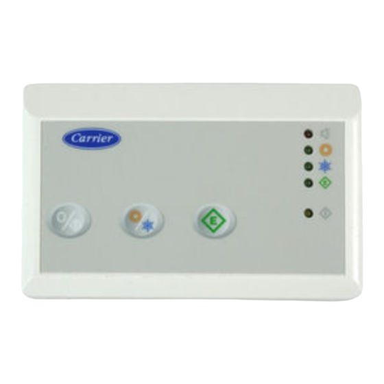
    Fernbedienung allgemeine Informationen und Daten Modelle wICHtIG: Kühlgerät/Wärmepumpe. Das gesamte Handbuch lesen, ehe mit der Installation begonnen wird. Produkte, die mit dem Fernbedienung verwendet werden können: 30aw. Für problemlose Installation, die von einem qualifizierten Verdrahtung Installateur durchgeführt werden sollte, die Installationsfolge •...
  • Seite 17: Fernbedienung Wahl Des Installationsortes Und Installation

    Fernbedienung wahl des Installationsortes und Installation D E U T S C H • Die hintere Montageplatte der Fernbedienung öffnen, um die • Länge und Verlegung jedes Kabels justieren, so daß es zur Montagelöcher freizulegen. entsprechenden Klemme im Klemmblock der Montageplatte Die Platte kann entfernt werden, um die Montage zu gelangt.
  • Seite 18: Schaltpläne

    Fernbedienung Schaltpläne Ein-Phasen-Gerät mit zubehör-Fernbedienung 30aw     Geräte-Stromtafel  Elektronikplatten-Anschlüsse  Fernbedienung Störungsermittlung Erforderliche Symptom Mögliche Ursache Lösung Maßnahme Leuchtdioden-Fehler 1) Fehlverdrahtung der 12-V- 1) Sicherstellen, daß das 30AW- Nach Abtrennen der Stromversorgung Versorgung an die Fernbedienung Gerät an die richtigen Klemmen der das Verdrahtungs-Problem beheben Fernbedienung angeschlossen ist.
  • Seite 19: Dimensiones (Mm)

    Control remoto Manual de instalación Este sistema de control sólo funciona con unidades 30AW. Para obtener información sobre las instrucciones de instalación de estas unidades, véanse los manuales respectivos. Índice Página Información general ..................... Características ......................Límites de funcionamiento ................... Escoger la ubicación ....................
  • Seite 20: Límites De Funcionamiento

    Control remoto Información general y características Modelos IMPoRtaNtE: Sólo refrigeración/bomba de calor. Leer detenidamente el manual de instrucciones antes de iniciar la instalación. Productos con los que puede funcionar el control remoto 30aw. • Para realizar una instalación sin problemas, que debería efectuar un instalador cualificado, seguir la secuencia indicada Conexiones en el gráfico de instalación.
  • Seite 21: Control Remoto

    Control remoto Escoger la ubicación y realizar la instalación E S PA Ñ O L • Abrir la base de montaje trasera del control remoto para • Ajustar la longitud y el recorrido de cada cable de forma que acceder a los taladros de fijación lleguen al terminal adecuado del conector de la base de La base puede retirarse para simplificar el montaje (hacer montaje.
  • Seite 22: Localización De Averías

    Control remoto Esquemas eléctricos Unidad monofásica con control remoto accesorio 30aw     Panel eléctrico de la unidad  Conectores de la placa electrónica  Control remoto Localización de averías Síntoma Causa posible acción requerida Solución Fallo del LED 1) Error de la conexión de la 1) Comprobar que la unidad 30AW Desconectar la alimentación, corregirel...
  • Seite 23 Bedieningspaneel Montage-instructies Dit regelsysteem werkt alleen met 30AW units: zie voor montage en onderhoudsinstructies van deze apparatuur de betreffende afzonderlijke handleidingen. Inhoud Blz. Algemene informatie ....................Kenmerken ........................Bedrijfslimieten ......................Plaats van opstelling ....................Elektrische aansluitingen ..................... Elektrische schema’s ....................Storingzoeken ......................
  • Seite 24: Algemene Informatie

    • Wanneer men zich niet houdt aan de montage-instructies dan vervalt de garantie. • Controleer de zending op transportschade. Meld eventuele zichtbare schade onmiddellijk telefonisch aan Carrier BV en laat de vervoerder een aantekening maken op de vrachtbrief. Installeer of gebruik geen beschadigde apparatuur.
  • Seite 25: Elektrische Aansluitingen

    Bedieningspaneel Plaats van opstelling en montage NEDERLANDS • Open het achterpaneel van het bedieningspaneel • Pas de lengte en de loop van iedere draad zo aan dat hij kan (montageplaat) zodat de bevestigingsgaten zichtbaar worden aangesloten op de juiste klem op de klemmenstrook op worden.
  • Seite 26: Elektrische Schema's

    Bedieningspaneel Elektrische schema’s Eén-fase unit met bedieningspaneel (accessoire) 30aw     Schakelkast unit  Connectors elektronische print  Bedieningspaneel Storingzoeken Probleem Mogelijke oorzaak wat te controleren oplossing LED elektrische voeding brandt niet 1) Foutieve bedrading van de 12 V 1) Controleer de juiste aansluiting Schakel de hoofdstroom af, herstel de voeding brandt niet...
  • Seite 27             30 W.       ,    .     .................... ......................  ......................   ..................  .................... ...
  • Seite 28       :    /  .     ,     .        30aw. •         , ...
  • Seite 29       E HNIK •       ( •          )                ...
  • Seite 30          30aw                                (LED) 1) ...
  • Seite 31: Comando Remoto

    Comando remoto Manual de instalação Este sistema de controlo funciona somente com unidades 30AW. Para as instruções de instalação destas unidades use como referência os manuais específicos. Índice Página Informações gerais ...................... Características ......................Limites de funcionamento .................... Escolha do lugar da instalação ..................Ligações eléctricas ......................
  • Seite 32: Limites De Funcionamento

    Comando remoto Informações gerais e características Modelos IMPoRtaNtE: antes de iniciar a instalação este manual deve ser lido com atenção. Só frio / Bomba de calor Produtos que podem ser instalados em interface com o 30aw. • A instalação deve ser efectuada por pessoal especializado, com o respeito da sequência de operações indicada no Fiação esquema de instalação.
  • Seite 33: Ligações Eléctricas

    Comando remoto Escolha do lugar da instalação e instalação PORTUGUÊS • Abra a base traseira do Comando remoto (base de montagem) • Regule o comprimento e o percurso de cada fio para o terminal para aceder aos furos de fixação à parede. A base pode ser certo da régua de bornes colocada na base de montagem.
  • Seite 34: Problemas E Soluções

    Comando remoto Esquemas eléctricos Unidade monofásica con acessório comando remoto 30aw     Quadro eléctrico unidade  Conectores placa electrónica  Comando remoto Problemas e soluções Sintoma Causa possível Controlo a efectuar Solução O LED não funciona 1) Ligação errada dos fios de 1) Verificar que as ligações à...
  • Seite 35 Fjärrkontroll Installationsmanual Detta kontrollsystem fungerar endast med enheten 30AW. Se respektive manual för installationsanvisningar för dessa enheter. Innehållsförteckning Sida Allmän information ....................... Egenskaper ......................... Driftsgränser ....................... Val av installationsplats ....................Elanslutningar ......................Elscheman ........................Problem och lösningar ....................INStaLLatIoNSSCHEMa Läsning av manualen Installation av fjärrkontrollen Nätanslutning av fjärrkontrollen...
  • Seite 36 Fjärrkontroll allmän information och egenskaper Modeller VIKtIGt! Endast kyla / Värmepump Läs denna manual noggrant innan installationen påbörjas. Produkter som kan användas tillsammans med fjärrkontrollen • Installationen ska utföras av specialiserad personal med 30aw. respekt för ordningsföljden som anges i installationsschemat. •...
  • Seite 37 Fjärrkontroll Val av installationsplats och installation S v E N S k A • Öppna den bakre basen för fjärrkontrollen (monteringsbas) för att • Reglera längden och dragningen för varje kabel mot korrekt komma åt hålen för fastsättning på väggen. kabelfäste på...
  • Seite 38: Problem Och Lösningar

    Fjärrkontroll Elscheman Enfasenhet med fjärrkontrolltillbehör 30aw     Elpanel, enhet  Kopplingsdon, elkort  Fjärrkontroll Problem och lösningar Problem Möjlig orsak Kontroll att utföra Lösning Lysdioden fungerar inte 1) Felaktig anslutning av 1) Kontrollera att anslutningarna till Koppla från matningen och åtgärda matningskablarna (12 V) 30AW-enheten är korrekta på...
  • Seite 39 Moduł zdalnego sterowania ę Podr cznik instalacji ą ą Ten system sterowania działa wył cznie z urz dzeniami 30AW. ą ź ę źć Instrukcje instalacji tego urz dzenia mo na znale w odpowiednich podr cznikach. ś Spis tre Strona Informacje ogólne ....................... Charakterystyka ......................
  • Seite 40: Informacje Ogólne

    Moduł zdalnego sterowania Informacje ogólne i charakterystyka Modele ć ę ż ę Ż NE: Przed rozpocz ciem instalacji nale y zapozna ę Tylko chłodzenie / pompa ciepła z całym podr cznikiem. Moduł zdalnego sterowania współpracuje z urządzeniami 30AW. • W celu bezproblemowej instalacji, która powinna być okablowanie przeprowadzona przez wykwalifikowanego instalatora, należy • Moduł zdalnego sterowania należy podłączyć do urządzenia 30AW. postępować zgodnie z kolejnością podaną w schemacie czynności instalacyjnych.
  • Seite 41: Poł Ą Czenia Elektryczne

    Moduł zdalnego sterowania wybór miejsca instalacji oraz instalacja P O L S k I • Otwórz tylną podstawę montażową modułu zdalnego sterowania, • Dostosuj długość i prowadzenie poszczególnych przewodów, aby aby uzyskać dostęp do otworów montażowych. sięgały odpowiednich styków bloku połączeniowego na podstawie Podstawa może zostać zdemontowana w celu ułatwienia montażu montażowej. (Aby zapobiec stykaniu się sąsiadujących przewodów (aby odłączyć podstawę montażową od obudowy modułu zdalnego po ich podłączeniu, z każdego przewodu usuń tylko 6 mm izolacji). sterowania, należy pociągnąć delikatnie za zaczepy). • Dopasuj i podłącz przewody urządzenia do odpowiednich styków • Przełóż przewody modułu zdalnego sterowania przez duży otwór w bloku połączeniowego. W celu prawidłowej pracy modułu zdalnego sterowania należy podstawie montażowej. Wypoziomuj podstawę montażową względem ściany (wyłącznie ze prawidłowo podłączyć zarówno przewody zasilania, jak i sygnałowe. względów estetycznych). • Wsuń wystające przewody pomiędzy ścianę i podstawę montażową. • Zaznacz na ścianie punkty w miejscu 2 otworów montażowych. W zaznaczonych punktach wywierć dwa otwory montażowe 5 mm. • Przymocuj podstawę montażową do ściany przy pomocy 2 śrub i kołków znajdujących się w zestawie (w razie potrzeby i w celu pewniejszego zamocowania można wykorzystać dodatkowe...
  • Seite 42: Schematy Okablowania

    Moduł zdalnego sterowania Schematy okablowania ą dzenie jednofazowe z dodatkowym modułem zdalnego sterowania 30aw    ą  Panel elektryczny urz dzenia ą  zł cza płytki elektroniki  Moduł zdalnego sterowania ą Rozwi zywanie problemów Objaw Prawdopodobna Wymagane działanie Rozwiązanie Awaria diody LED 1) Brak dostarczanego zasilania 12 V do...
  • Seite 44 L010128H97 - 0210 Via R. sanzio, 9 - 20058 Villasanta (MI) Italy - tel. 039/3636.1 The manufacturer reserves the right to change any product specifications without notice. La cura costante per il miglioramento del prodotto può comportare senza preavviso, cambiamenti o modifiche a quanto descritto. La recherche permanente de perfectionnement du produit peut nécessiter des modifications ou changements, sans préavis.

Inhaltsverzeichnis