Herunterladen Inhalt Inhalt Diese Seite drucken
Inhaltsverzeichnis

Werbung

Verfügbare Sprachen
  • DE

Verfügbare Sprachen

  • DEUTSCH, seite 1
www.vdo-marine.com
OceanLink - 7" TFT-Display
Bedienungsanleitung v. 1.0
OceanLink - 7" TFT display
Operating instruction v. 1.0
OceanLink - Écran 7" TFT
Notice d'utilisation v. 1.0
OceanLink - Display 7" TFT
Instrucciones para el uso v. 1.0
OceanLink - Display 7" TFT
Istruzioni per l'uso v. 1.0

Werbung

Inhaltsverzeichnis
loading

Inhaltszusammenfassung für VDO OceanLink

  • Seite 1 OceanLink - 7" TFT-Display Bedienungsanleitung v. 1.0 OceanLink - 7” TFT display Operating instruction v. 1.0 OceanLink - Écran 7” TFT Notice d’utilisation v. 1.0 OceanLink - Display 7” TFT Instrucciones para el uso v. 1.0 OceanLink - Display 7” TFT...
  • Seite 3 Deutsch ........ 5 English ........ 45 Français ........ 85 Español ........ 125 Italiano ........ 165...
  • Seite 5 OceanLink - 7" TFT-Display Bedienungsanleitung v. 1.0...
  • Seite 7: Inhaltsverzeichnis

    Diese Anleitung bezieht sich auf die Software-Version 00:07. Die Version wird beim Einschalten angezeigt. Kundendienst und Garantie Bei Störungen oder Fehlern bzw. wenn Sie Auskünfte zur Garantie benötigen, kontaktieren Sie bitte die VDO-Partner. Einen geeigneten Partner finden Sie auf der Website www.vdo-partner.com.
  • Seite 8: Allgemeine Informationen

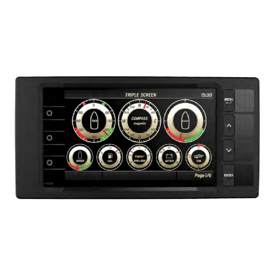
    Allgemeine Informationen Beschreibung OceanLink Master 7" ist ein Multifunktionsdisplay zur Überwachung der Parameter der Motoren und der dazugehörigen Sensoren. An das Display können bis zu vier Motoren angeschlossen werden. Das integrierte NMEA 2000-Gateway ermöglicht die Erfassung der Motordaten auch über Analogsignale oder SAE J1939 zur anschließenden Konvertierung und Weiterleitung in das NMEA 2000-Netzwerk.
  • Seite 9: Priorität Der Empfangenen Signale

    3. NMEA 2000 Einschalten/Ausschalten Die Art des Einschaltens/Ausschaltens ist vom Anschluss abhängig, der beim Einbau gewählt wurde. Beim Einschalten werden das VDO-Logo und die Software-Version gefolgt von einer Sicherheitsmeldung angezeigt; anschließend wird die vor dem Ausschalten zuletzt angezeigte Datenseite geöffnet.
  • Seite 10: Konfigurieren Des Displays

    Allgemeine Informationen Taste Funktion Kurzer Tastendruck: Aufruf des Untermenüs Bestätigen der Auswahl Langer Tastendruck: Auf der Seite MediaBox: Speichern der Radiofrequenz für die ausgewählte Station Kurzer Tastendruck: Anzeige der Datenseite, die der Taste zugeordnet ist Langer Tastendruck: Zuordnung der angezeigten Datenseite zur Taste Konfigurieren des Displays Folgende Schritte sind bei der Erstkonfiguration auszuführen: 1.
  • Seite 11: Datenseiten

    Datenseiten Was sind Datenseiten? Die Datenseiten zeigen die von den verschiedenen Quellen empfangenen Daten an. Es sind bis zu 10 Datenseiten möglich. Standardmäßig werden vier Datenseiten und eine MediaBox-Seite angezeigt. Die Seite ALARMS wird am Ende der Datenseiten angezeigt, wenn aktive Alarme anstehen. Mögliche Operationen Zum Blättern durch die Seiten oder...
  • Seite 12 Datenseiten Eingangssignal Ausgangssignal Symbol Bezeichnung Maßeinheit NMEA NMEA Analogsensor EasyLink 2000 J1939 2000 Motorkühlmitteltemperatur °C / °F Batteriespannung Kraftstoffverbrauch gal/h oder l/h Motoröltemperatur °C / °F Motoröldruck bar / psi / kPa Motorbetriebsstunden gesamt Ruderwinkel °S (Steuerbord) / °P (Backbord) Tiefe unter Kiel m / ft Füllstand Kraftstoff...
  • Seite 13: Konfiguration Der Datenseiten

    Konfiguration der Datenseiten Konfiguration über Layout Jede Seite des Displays kann mit fünf konfigurierbaren Layouts, einem festen Layout für die MediaBox- Befehle und einem festen Layout für die Videoeingänge personalisiert werden. Beschreibung der Layouts Layout SINGLE: Nur ein Quadrant. Der Datenwert ist Layout GRAPH: mit drei Balkenanzeigen für drei beliebig zwischen nummerisch oder wird mithilfe eines Zeigers angezeigt.
  • Seite 14: Im Layout Nav Dash Anzeigbare Daten

    Konfiguration der Datenseiten Layout RADIO: Seite für die MediaBox. Siehe "Verwendung Layout NAV DASH: Layout mit zwei, drei oder acht der MediaBox" auf Seite 33. konfigurierbaren analogen Anzeigen (siehe "Im Layout Nav Dash anzeigbare Daten" unten) Layout VIDEO: Anzeige Video-Eingabe. Im Layout Nav Dash anzeigbare Daten Anzeigen Anzeigbare Daten...
  • Seite 15: Hinzufügen Einer Seite Mit Einem Quadranten-Layout

    Konfiguration der Datenseiten Hinzufügen einer Seite mit einem Quadranten-Layout Nachstehend ist beispielhaft beschrieben, wie eine Seite zur Anzeige von fünf Daten hinzugefügt wird (zwei Daten in eigenen Quadranten und drei Daten in einem Dreifach-Quadranten). Hinweis: Im Konfigurationsmodus sind die Touchscreen-Funktionen nicht aktiviert. Zum Blättern durch die Seiten die Tasten oder verwenden.
  • Seite 16: Entfernen Einer Seite

    Konfiguration der Datenseiten 4. ENTER drücken: Die Mitte der Anzeige wird rot. 5. Durchblättern und die gewählten Daten auswählen: Die Mitte der Anzeige wird wieder grün. 6. Durchblättern, sich auf der nächsten Anzeige positionieren und die Schritte 4 und 5 wiederholen. 7.
  • Seite 17: Systemeinstellungen

    Systemeinstellungen Schema Menü SYSTEM CONFIG Hinweis *: Die angezeigten Maßeinheiten hängen vom Parameter SYSTEM CONFIG > Units ab. 7" TFT-Display | Bedienungsanleitung v. 1.0 | © 2018 Continental Automotive Switzerland AG...
  • Seite 18: Beschreibung Des Menüs System Config

    Systemeinstellungen Beschreibung des Menüs SYSTEM CONFIG Hinweis: Der unterstrichene Wert/Befehl ist der Standardwert/-befehl. Die Maßeinheiten hängen vom Parameter SYSTEM CONFIG > Units ab. Einstellung Beschreibung Mögliche Werte/Befehle Display > Helligkeit des Displays und der Illumination angeschlossenen Anzeigegeräte (52 mm) Display > Intervall (Werte Hi und Lo) der Boost press: 0–13 bar Bargraph settings...
  • Seite 19: Maßeinheit

    Systemeinstellungen Maßeinheit Daten Metric Imperial Nautical Custom Boat speed kmh, mph, kn Wind speed kmh, kn, m/s, bft Depth m, ft Pressure bar, psi, Fuel l, gal Fuel flow l/h, gph Temperature °C °F °F °C, °F Dämpfung Diese Funktion dient der Stabilisierung der angezeigten Werte. Sie ist für die Wind- und Kompassdaten verfügbar.
  • Seite 20: Handhabung Von Alarmen

    Handhabung von Alarmen Modalitäten für Alarmmeldungen Die angezeigten Alarme werden vom NMEA 2000/SAE J1939-Netzwerk gelesen oder vom Display verarbeitet. Dabei werden die vom Netzwerk oder von den Analogsignalen empfangenen Daten mit den eingestellten Schwellen verglichen. Die Motoralarme betreffen alle im Netzwerk vorhandenen Motoren und Sensoren.
  • Seite 21: Quittieren Eines Alarms

    Handhabung von Alarmen Schema Menü ALARMS Quittieren eines Alarms Beim Auftreten eines Alarms wird die Seite Alarm angezeigt und der Alarmsummer (falls angeschlossen) aktiviert. Um den Alarm zu quittieren und den Alarmsummer stumm zu schalten, eine beliebige Taste auf der Tastatur drücken: Die Seite wird geschlossen und der Alarm wird auf der Seite Active alarms gespeichert.
  • Seite 22: Alarme Auf Mehreren Displays

    4. Falls erforderlich, die Alarmmeldung über das Fenster Alarm aktivieren/deaktivieren und den Alarmsummer aktivieren/deaktivieren. Alarme auf mehreren Displays Wenn im NMEA 2000-Netzwerk mehrere OceanLink-Displays vorhanden sind, genügt es, die Alarme über eines der Geräte zu konfigurieren. Die Konfiguration wird automatisch auf die übrigen Geräte übertragen.
  • Seite 23: Liste Der Möglichen Alarme

    Handhabung von Alarmen Mögliche Alarm Beschreibung Standard Werte/Befehle Min RPM Untere Schwelle Motordrehzahl. Nur die unter der Schwelle liegenden 0 -990 rpm 300 rpm Werte werden für die Aktivierung der Motoralarme berücksichtigt. Zugriff auf die Alarme von CAN-Bus (NMEA 2000 und J1939). Siehe "Liste der möglichen Alarme"...
  • Seite 24: Konfiguration Der Sensoren

    Konfiguration der Sensoren Zuordnung Sensor-Motor Alle von den Sensoren abgelesenen Motordaten werden vor der Konvertierung und der Übermittlung über das NMEA 2000-Netzwerk dem entsprechenden überwachten Motor zugeordnet. Schema Menü SENSOR CONFIG Es können nur Sensoren konfiguriert und/oder kalibriert werden, die an die Analogeingänge des Displays angeschlossen sind.
  • Seite 25 Konfiguration der Sensoren 7" TFT-Display | Bedienungsanleitung v. 1.0 | © 2018 Continental Automotive Switzerland AG...
  • Seite 26 Konfiguration der Sensoren 7" TFT-Display | Bedienungsanleitung v. 1.0 | © 2018 Continental Automotive Switzerland AG...
  • Seite 27: Wann Soll Ein Sensor Kalibriert Werden

    Konfiguration der Sensoren Wann soll ein Sensor kalibriert werden Die VDO-Sensoren erfordern keine Kalibrierung; vielmehr ordnet ihnen das Display beim Erkennen Standardwerte zu. Es ist ausreichend, den Sensortyp festzulegen, und der Sensor beginnt mit dem Lesen des Werts in guter Annäherung.
  • Seite 28: Konfiguration Und Kalibrierung Des Sensors Für Den Kraftstofffüllstand

    Konfiguration der Sensoren Konfiguration und Kalibrierung des Sensors für den Kraftstofffüllstand 1. Die Taste MENU drücken und SENSOR CONFIG auswählen. 2. Mit Engine 1 connector oder Engine 2 connector den Stecker auswählen, an den der Sensor angeschlossen ist. 3. Den Eingang auswählen, an den der Sensor angeschlossen ist (z. B.
  • Seite 29: Konfiguration Und Kalibrierung Der Übrigen Sensoren

    Konfiguration der Sensoren Konfiguration und Kalibrierung der übrigen Sensoren Nachstehend wird die Vorgehensweise für die Konfiguration und Kalibrierung der Sensoren Trimmung, Füllstand Frischwasser, Füllstand Schmutzwasser und Ruderwinkel beschrieben: 1. Die Taste MENU drücken und SENSOR CONFIG auswählen. 2. Mit Engine 1 connector oder Engine 2 connector den Stecker auswählen, an den der Sensor angeschlossen ist.
  • Seite 30 Konfiguration der Sensoren Sensortypen Stecker 1 Hinweis: Der unterstrichene Wert/Befehl ist der Standardwert/-befehl. Die Maßeinheiten hängen vom Parameter SYSTEM CONFIG > Units ab. Einstellung Beschreibung Mögliche Werte/Befehle Frequency pin 4 Impulse pro Motorumdrehung. Wenn Off / On aktiv, wird die Motordrehzahl vom Show value as: Engine 1 - 4.
  • Seite 31 Konfiguration der Sensoren Sensortypen Stecker 2 Hinweis: Der unterstrichene Wert/Befehl ist der Standardwert/-befehl. Die Maßeinheiten hängen vom Parameter SYSTEM CONFIG > Units ab. Einstellung Beschreibung Mögliche Werte/Befehle Frequency pin 4 Impulse pro Motorumdrehung. Wenn Off / On aktiv, wird die Motordrehzahl vom Show value as: Engine 1 - 4.
  • Seite 32: Typen Der An Das Nmea 2000-Netzwerk Angeschlossenen Sensoren

    Konfiguration der Sensoren Typen der an das NMEA 2000-Netzwerk angeschlossenen Sensoren Hinweis: Der unterstrichene Wert/Befehl ist der Standardwert/-befehl. Die Maßeinheiten hängen vom Parameter SYSTEM CONFIG > Units ab. Mögliche Einstellung Beschreibung Werte/Befehle Abgleich zwischen Kompasskurs und Bootskurs. Compass > Heading ± 0,0 – 180 ° (0 °) offset Abgleich zwischen magnetischem Norden und tatsächlichem Norden.
  • Seite 33: Verwendung Der Mediabox

    Verwendung der MediaBox Funktionsweise Die MediaBox kann vom OceanLink 7" TFT-Display oder von der App VDO MediaBox, die für Apple- und Android-Geräte in den jeweiligen Stores zur Verfügung steht, bedient werden. Die App ermöglicht die Fernsteuerung der MediaBox. Folgende Quellen können verwaltet werden:...
  • Seite 34: Anhören Von Fm/Am-Stationen

    Verwendung der MediaBox 2. Die Taste ENTER drücken: Die Hauptseite mit dem roten Symbol Power OFF wird angezeigt. 3. Erneut die Taste ENTER drücken: Die MediaBox wird eingeschaltet. 4. Erneut die Taste ENTER drücken: Die MediaBox wird ausgeschaltet. Hinweis : Wenn keine USB- und BT-Quellen angeschlossen sind, sind die entsprechenden Menüs deaktiviert.
  • Seite 35: Anhören Einer Playlist Von Einem Usb-Stick

    Verwendung der MediaBox 3. Mit den Tasten oder bis zu jener Position blättern, in der die Station eingestellt werden kann, und die Taste ENTER zum Speichern gedrückt halten. Anhören einer Playlist von einem USB-Stick 1. Den USB-Stick mit den Playlists in den Port stecken.
  • Seite 36: Funktionseinstellungen Der Mediabox

    Verwendung der MediaBox Funktionseinstellungen der MediaBox 1. Mehrmals die Taste MENU drücken, um sich auf der Menüleiste zu positionieren. Durchblättern und mit der Taste ENTER auswählen. 2. Zum Einstellen des Tons durchblättern und Equalizer auswählen. 3. Um die richtigen Frequenzen für das geografische Gebiet zu erhalten, Tuner region auswählen.
  • Seite 37: Verwendung Von Vdo Marine Configuration Tool

    Funktionsweise VDO Marine Configuration Tool kommuniziert mit den an das NMEA 2000-Netzwerk angeschlossenen Geräten über das VDO Diagnostic Tool, das über USB an den PC angeschlossen wird. Für weitere Informationen und Anleitungen zur Verwendung von VDO Marine Configuration Tool siehe die Benutzeranleitung „VDO Marine Configuration Tool User manual“ auf der Website www.vdo- marine.com.
  • Seite 38: Problemlösung

    Problemlösung Probleme mit der Anzeige Problem Ursache Abhilfe Die anzeigten Werte Falsche Konfiguration des Die Konfiguration im Menü Sensor config prüfen. entsprechen nicht den Sensors. Erwartungen. Sensor falsch angeschlossen. Den Anschluss prüfen; siehe Installationsanleitung. Das Backbone des NMEA 2000- Die Anschlüsse prüfen und prüfen, ob sowohl am Anfang als Netzwerks wurde nicht auch am Ende des Backbones Abschlüsse vorhanden sind.
  • Seite 39: Technische Daten

    6 resistive Analogeingänge (0–400 Ω) 2 Frequenzeingänge (0–4 kHz) 3 Spannungseingänge (0–5 V) 1 digitaler Alarmeingang Ausgangsdaten NMEA 2000 2 EasyLink-Ausgänge (proprietäres Protokoll von VDO) zu Anzeigegeräten (52 2 Alarmausgänge (500 mA) Schutzart IPX7 Display TFT 7" Maximal 16 pro Kanal (32 insgesamt) Anzeigegeräte (52 mm)
  • Seite 40: Verantwortung Für Die Entsorgung

    Technische Daten Verantwortung für die Entsorgung Die Entsorgung hat mit getrennter Sammlung über die von den staatlichen oder örtlichen Behörden angegebenen Sammelstellen zu erfolgen. Die ordnungsgemäße Entsorgung und das Recycling tragen dazu bei, potenziell nachteilige Auswirkungen für die Umwelt und Personen zu vermeiden. 7"...
  • Seite 41: Ersatzteile, Sensoren Und Zubehör

    Frontring, weiß A2C1697540001 Frontring, schwarz A2C1697530001 Sonnenschutzabdeckung A2C59501973 EasyLink-Verlängerungskabel A2C1650700001 Kabel mit Videostecker A2C1845710001 Verfügbares Zubehör Informationen zum gesamten verfügbaren Zubehör finden Sie auf der Website www.vdo-marine.com. 7" TFT-Display | Bedienungsanleitung v. 1.0 | © 2018 Continental Automotive Switzerland AG...
  • Seite 42: Anhang

    Anhang Unterstützte NMEA 2000-Meldungen Beschreibung Beschreibung 65030 J1939 Generator Average Basic AC Quantities 129285 Navigation route and waypoint info 65226 J1939 Diagnostic Message #1 129539 GNSS dilution of precision (DOP) 65227 J1939 Diagnostic Message #2 129540 GNSS satellites in view 65228 J1939 Diagnostic Message #3 130306 Wind data 65229...
  • Seite 43: Unterstützte Sae J1939-Meldungen

    Anhang Unterstützte SAE J1939-Meldungen Beschreibung 61443 Engine Percent Load ar Current Speed 61444 Actual Engine - Percent Torque 61444 Engine Speed 61445 Transmission Current Gear 65030 Generator Average Line to Line Voltage 65030 Generator Average Frequency 65030 Generator Average Line to Neutral Voltage 65030 Generator Average Current...
  • Seite 44 9464 Rüthi Switzerland www.vdo-marine.com VDO – A Trademark of the Continental Corporation Jede Weitergabe, Änderung, Übersetzung oder Vervielfältigung des gesamten Dokuments oder von Teilen desselben ist untersagt und bedarf der schriftlichen Zustimmung von Continental Automotive Switzerland AG. Davon ausgenommen sind folgende Tätigkeiten: Ausdruck des vollständigen Dokuments oder von Teilen desselben im Originalformat.
  • Seite 45 OceanLink - 7” TFT display Operating instruction v. 1.0...
  • Seite 47: Customer Service And Warranty

    The version is displayed when turned on. These instructions are always updated and available in several languages at www.vdo-marine.com. Customer service and warranty In the event of malfunction, fault or for information on the warranty, contact a VDO partner. To find a partner, visit www.vdo-partner.com.
  • Seite 48: Getting Started

    NMEA 2000 monitor. Operations OceanLink Display 7” TFT is a versatile device. It lets you control all connected engines in a single monitoring point and at the same time. The motor whose data is displayed is selected during data page configuration.
  • Seite 49: Button Functions

    Getting started On/Off The on/off mode depends on the connection made during installation. The VDO logo and software version followed by a security message appear when turned on followed by the last data page viewed before turned off. Page Calibration wizard Page Calibration wizard appears when first turned on after reset and every time turned on until sensors are calibrated.
  • Seite 50 Getting started 5. If a page layout with bar graphs is used, customize the minimum and maximum intervals (Bargraph settings, see "System settings" on page 57). 6. Enable/disable local input and NMEA 2000 and J1939 alarms (see "Alarm management" on page 60). 7”...
  • Seite 51: Data Pages

    Data pages What are data pages Data pages display data received from the various sources. There can be up to 10 data pages. Four data pages and a MediaBox page are displayed by default. The ALARMS page appears after data pages if alarms are triggered.
  • Seite 52 Data pages Input signal Output signal Unit of Icon Information NMEA Analog NMEA measure EasyLink 2000 J1939 sensor 2000 Engine coolant temperature °C / °F Battery voltage Fuel consumption gal/h or l/h Engine oil temperature °C / °F Engine oil pressure bar / psi / kPa Total engine operating hours Rudder angle...
  • Seite 53: Data Page Configuration

    Data page configuration Configuration via layout Each display page can be customized using five editable layouts, a default layout for MediaBox commands and a default layout for video inputs. Layout description Layout SINGLE: single box. The data value is numeric or Layout GRAPH: with three bar graphs for the three data displayed by a gauge.
  • Seite 54: Viewable Data In Nav Dash Layout

    Data page configuration Layout RADIO: MediaBox page. See "MediaBox use" on Layout NAV DASH: two, three or eight editable analog gauge page 73. layout (see "Viewable data in Nav Dash layout" below) Layout VIDEO: video input display. Viewable data in Nav Dash layout Gauges Viewable data Nav Dash 1...
  • Seite 55: Add A Page With An Analog Gauge Layout

    Data page configuration 1. Press the MENU button and select SCREEN CONFIG. 2. Scroll until you see an empty page ("NO SCREEN") and select it. 3. Scroll and select the page layout TRIPLE: the layout opens with the first box green. 4.
  • Seite 56 Data page configuration 3. Scroll and select the page layout REMOVE: the layout NO SCREEN appears in correspondence to the page. 4. Hold down the MENU button to save settings and return to the data page. Note: the deleted page disappears. To add it again, see examples "Add a page with box layout" on page 54, "Add a page with a bar graph layout"...
  • Seite 57: System Settings

    System settings Menu layout SYSTEM CONFIG Note*: the units of measure depend on parameter SYSTEM CONFIG > Units 7” TFT display | Operating instruction v. 1.0 | © 2018 Continental Automotive Switzerland AG...
  • Seite 58 System settings Menu description SYSTEM CONFIG Note: the underlined value/command is the default value/command. The units of measure depend on parameter SYSTEM CONFIG > Units Setting Description Possible values/commands Display > Display and connected 52 mm Illumination gauges brightness Display > Bar graph interval (values Hi and Lo) Boost press: 0–13 bar Bargraph settings...
  • Seite 59: Unit Of Measure

    System settings Unit of measure Data Metric Imperial Nautical Custom Boat speed kmh, mph, kn Wind speed kmh, kn, m/s, bft Depth m, ft Pressure bar, psi, Fuel l, gal Fuel flow l/h, gph Temperature °C °F °F °C, °F Damping (Damping) The function makes the displayed values more stable.
  • Seite 60: Alarm Management

    Alarm management Signal mode The displayed alarms are read by the NMEA 2000/SAE J1939 network or are processed by the display comparing the data received from the network or analog signals to the thresholds set. Engine alarms concern all engines on the network. When an alarm is triggered, the Alarm page appears and then disappears after the alarm is acknowledged.
  • Seite 61: Acknowledge An Alarm

    Alarm management Menu layout ALARMS Acknowledge an alarm When an alarm is triggered, the Alarm page appears and the buzzer sounds (if connected). To acknowledge the alarm and mute the buzzer, press any button on the keyboard: the page closes and the alarm is saved in the Active alarms page.
  • Seite 62 Alarm management Alarms on several displays If there are several OceanLink displays on the NMEA 2000 network, simply configure alarms from one of the devices. Configuration is automatically transmitted to the others. When an alarm triggers, the Alarm page appears on all displays. After acknowledging the alarm from one device, the page disappears on all others.
  • Seite 63 Alarm management Managed alarms list NMEA2000 - Engine Parameters, SAE J1939 - Active Diagnostic Trouble Dynamic (PGN 127489) Codes (DM1) Check engine Engine speed Over temperature Boost pressure Low oil pressure Exhaust gas temperature Low oil level Engine oil pressure Low fuel pressure Engine coolant pressure Low system voltage...
  • Seite 64: Sensor Configuration

    Sensor configuration Sensor-engine link All values read by the sensors concerning engines are linked to the monitored engine before being converted and sent on the NMEA 2000 network. Menu layout SENSOR CONFIG Only sensors connected to display analog inputs can be configured and/or calibrated. Note*: the units of measure depend on parameter SYSTEM CONFIG >...
  • Seite 65 Sensor configuration 7” TFT display | Operating instruction v. 1.0 | © 2018 Continental Automotive Switzerland AG...
  • Seite 66 Sensor configuration 7” TFT display | Operating instruction v. 1.0 | © 2018 Continental Automotive Switzerland AG...
  • Seite 67 Sensor configuration When to calibrate a sensor VDO sensors do not require calibration. The display recognizes them and applies default values. Simply declare the type and the sensor starts reading the value with good approximation. For third party sensors or for more accurate readings, calibrate the sensor. Calibration occurs with subsequent readings (at one or three points) with a wizard.
  • Seite 68 Sensor configuration Configure and calibrate the fuel level sensor 1. Press the MENU button and select SENSOR CONFIG. 2. Use Engine 1 connector or Engine 2 connector to select the connector to which the sensor is connected. 3. Select the input connected to the sensor (i.e. Resistive pin 8): "Off"...
  • Seite 69 Sensor configuration Configure and calibrate the other sensors Following is the procedure to configure and calibrate Trim, Fresh water level, Waste water level and Rudder angle sensors: 1. Press the MENU button and select SENSOR CONFIG. 2. Use Engine 1 connector or Engine 2 connector to select the connector to which the sensor is connected.
  • Seite 70 Sensor configuration Connector 1 sensor types Note: the underlined value/command is the default value/command. The units of measure depend on parameter SYSTEM CONFIG > Units Setting Description Possible values/commands Frequency pin 4 Impulses per engine revolution. If Off / On enabled, engine revolutions are read Show value as: Engine 1 - 4.
  • Seite 71 Sensor configuration Connector 2 sensor types Note: the underlined value/command is the default value/command. The units of measure depend on parameter SYSTEM CONFIG > Units Setting Description Possible values/commands Frequency pin 4 Impulses per engine revolution. If Off / On enabled, engine revolutions are read Show value as: Engine 1 - 4.
  • Seite 72 Sensor configuration Sensor types connected to the NMEA 2000 network Note: the underlined value/command is the default value/command. The units of measure depend on parameter SYSTEM CONFIG > Units Possible Setting Description values/commands Alignment between compass bow and boat bow. Compass >...
  • Seite 73: Mediabox Use

    MediaBox use Operations MediaBox can be controlled by OceanLink7" TFT display or the VDO MediaBox app available for Apple and Android devices in their stores. The app lets you remotely control MediaBox. It can control the following sources: FM stations...
  • Seite 74: Listen To Fm/Am Radio Stations

    MediaBox use 2. Press the button ENTER: the main page appears with the Power OFF red symbol. 3. Press the button ENTER again: MediaBox turns on. 4. Press the button ENTER again: MediaBox turns off. Note : if the USB and BT sources are not connected, their menus are disabled.
  • Seite 75 MediaBox use 3. Use the button to move to the position where the station will be set and hold down the ENTER button to save. Listen to a playlist from USB key 1. Insert the USB key with the playlist. 2.
  • Seite 76 MediaBox use Set MediaBox operations 1. Repeatedly press the MENU button until positioned on the menu bar. Scroll and select by pressing the ENTER button. 2. To adjust the volume, scroll and select Equalizer . 3. To obtain the correct frequencies for the geographical area, select Tuner region.
  • Seite 77: Vdo Marine Configuration Tool Use

    VDO Marine Configuration Tool communicates with devices connected on the NMEA 2000 network through VDO Diagnostic Tool that is connected to the PC via USB. For further information and instructions for use on VDO Marine Configuration Tool, see VDO Marine Configuration Tool User manual available at www.vdo-marine.com.
  • Seite 78: Troubleshooting

    Troubleshooting Display problems Problem Cause Solution The displayed values Incorrect sensor configuration. Check configuration in menu Sensor config. are not those Incorrectly connected sensor. Check the connection, refer to the Installation instruction. expected. The NMEA 2000 network Check connections and make sure there is a termination at backbone was incorrectly created.
  • Seite 79: Technical Specifications

    6 resistive analog inputs (0–400 Ω) 2 frequency inputs (0–4 kHz) 3 voltage inputs (0–5 V) 1 digital alarm input Output data NMEA 2000 2 EasyLink outputs (VDO proprietary protocol) to 52 mm gauges 2 output alarms (500 mA) Protection grade IPX7 Display TFT 7"...
  • Seite 80: Disposal Instructions

    Technical specifications Disposal instructions Separate waste and use the collection centers indicated by the government or local public agencies. Correct disposal and recycling will contribute to the prevention of potentially harmful consequences to the environment and population. 7” TFT display | Operating instruction v. 1.0 | © 2018 Continental Automotive Switzerland AG...
  • Seite 81: Spare Parts, Sensors And Accessories

    White bezel A2C1697540001 Black bezel A2C1697530001 Sun cover A2C59501973 EasyLink extension cable A2C1650700001 Cable with video connector A2C1845710001 Available accessories To view available accessories, visit www.vdo-marine.com. 7” TFT display | Operating instruction v. 1.0 | © 2018 Continental Automotive Switzerland AG...
  • Seite 82: Appendix

    Appendix Supported NMEA 2000 messages Description Description 65030 J1939 Generator Average Basic AC Quantities 129284 Navigation data 65226 J1939 Diagnostic Message #1 129285 Navigation route and waypoint info 65227 J1939 Diagnostic Message #2 129539 GNSS dilution of precision (DOP) 65228 J1939 Diagnostic Message #3 129540 GNSS satellites in view 65229...
  • Seite 83 Appendix Description 65176 1180 Exhaust Temperature Description 65214 Engine Rated Speed 65226 Amber Warning 65226 Red Stop 65226 Protect lamp 65226 3098 MIL 65242 Software Identification 65260 Vehicle Identification Number 65262 Engine Coolant Temperature 65262 Engine Oil Temperature 1 65263 Engine Fuel Delivery Pressure 65263 Engine Oil Pressure...
  • Seite 84: Www.vdo-Marine.com

    Switzerland www.vdo-marine.com VDO – A Trademark of the Continental Corporation Any distribution, translation or reproduction, partial or total, of the document is strictly prohibited unless with prior authorization in writing from Continental Automotive Switzerland AG, with the exception of the following actions: Printing the document in its original format, totally or partially.
  • Seite 85 OceanLink - Écran 7” TFT Notice d’utilisation v. 1.0...
  • Seite 87 La version est visible à la mise en marche. Assistance clients et garantie En cas de dysfonctionnement ou de panne ou pour des informations concernant la garantie, veuillez vous adresser à un revendeur VDO. Pour trouver un revendeur, veuillez visiter le site www.vdo-partner.com.
  • Seite 88: Pour Commencer

    NMEA 2000. Fonctionnement L’écran Oceanlink 7” TFT est un appareil polyvalent. Il permet, depuis un point de surveillance unique et en même temps, de contrôler le fonctionnement de tous les moteurs connectés. La sélection du moteur pour lequel afficher les données est effectuée lors de la configuration des pages de données.
  • Seite 89: Fonction Des Boutons

    Le mode marche/arrêt dépend de la connexion effectuée lors de la phase d’installation. À la mise en marche, le logo VDO et la version du logiciel sont affichés suivis d'un message de sécurité, puis la dernière page de données affichée avant l'arrêt s’ouvre.
  • Seite 90 Pour commencer Configurer l'écran Ci-après les étapes à suivre pour la première configuration : 1. Connecter d’éventuels capteurs aux entrées analogiques. 2. À la mise en marche, lire le message de sécurité, puis sélectionner Yes pour ouvrir le menu SENSOR CONFIG et procéder à la configuration des capteurs (voir "Configuration des capteurs" à la page 104).
  • Seite 91: Pages De Données

    Pages de données À quoi servent les pages de données Les pages de données montrent les données reçues par les différentes sources. Il peut y avoir jusqu'à 10 pages de données affichées. Par défaut, il y a quatre pages de données affichées et une page MediaBox.
  • Seite 92 Pages de données Signal d’entrée Signal de sortie Unité de Icône Information NMEA Capteur NMEA mesure EasyLink 2000 J1939 analogique 2000 Température du liquide de refroidissement °C / °F du moteur Tension de la batterie Consommation de carburant gal/h ou l/h Température de l'huile du moteur °C / °F Pression de l’huile du moteur...
  • Seite 93: Configuration Des Pages De Données

    Configuration des pages de données Configuration via la disposition Chaque page de l’écran peut être personnalisée grâce à cinq dispositions configurables, une disposition fixe pour les commandes de MediaBox, une disposition fixe pour les entrées vidéo. Description des dispositions Disposition SINGLE : un seul cadran. La valeur de la donnée Disposition GRAPH : avec trois indicateurs à...
  • Seite 94 Configuration des pages de données Disposition RADIO : page pour MediaBox. Voir "Utilisation de Disposition NAV DASH : disposition avec deux, trois ou huit MediaBox" à la page 113. indicateurs analogiques configurables (voir "Données affichables dans la disposition Nav Dash" plus bas) Disposition VIDEO : affichage d’entrée vidéo.
  • Seite 95 Configuration des pages de données Ajouter une page avec disposition à cadrans Ci-après un exemple montrant comment ajouter une page pour afficher cinq données (deux données dans des cadrans individuels et trois données dans un cadran triple). Remarque : en mode de configuration, les fonctions de l’écran tactile ne sont pas activées. Pour faire défiler les pages et les dispositions, utiliser les boutons 1.
  • Seite 96 Configuration des pages de données 7. Faire défiler et se positionner sur le dernier indicateur, puis répéter les étapes 4 et 5. 8. Maintenir appuyé le bouton MENU pour enregistrer les paramètres et revenir aux pages de données. Éliminer une page 1.
  • Seite 97: Réglages Du Système

    Réglages du système Schéma du menu SYSTEM CONFIG Remarque* : les unités de mesure affichées dépendent du paramètre SYSTEM CONFIG > Units Écran 7” TFT | Notice d’utilisation v. 1.0 | © 2018 Continental Automotive Switzerland AG...
  • Seite 98 Réglages du système Description du menu SYSTEM CONFIG Remarque : la valeur/commande soulignée est celle par défaut. Les unités de mesure dépendent du paramètre SYSTEM CONFIG > Units Paramètre Description Valeurs/commandes possibles Display > Luminosité de l'écran et des Illumination indicateurs 52 mm connectés Display >...
  • Seite 99: Unité De Mesure

    Réglages du système Unité de mesure Donnée Metric Imperial Nautical Custom Boat speed kmh, mph, kn Wind speed kmh, kn, m/s, bft Depth m, ft Pressure bar, psi, Fuel l, gal Fuel flow l/h, gph Temperature °C °F °F °C, °F Amortissement La fonction rend les valeurs affichées plus stables.
  • Seite 100: Gestion Des Alarmes

    Gestion des alarmes Modalités de signalisation Les alarmes affichées sont lues par le réseau NMEA 2000/SAE J1939 ou sont traitées par l'écran en comparant les données reçues à partir du réseau ou des signaux analogiques avec les seuils définis. Les alarmes des moteurs concernent tous les moteurs et les capteurs présents dans le réseau. Lorsqu’une alarme se déclenche, la page Alarm apparaît et elle disparait lorsque l'alarme a été...
  • Seite 101 Gestion des alarmes Schéma du menu ALARMS Acquitter une alarme Lorsqu’une alarme se déclenche, la page Alarm apparaît et l'avertisseur sonore retentit (s’il est connecté). Pour acquitter l’alarme et faire taire l’avertisseur sonore, appuyer sur n’importe quelle touche du clavier : la page se ferme et l’alarme est enregistrée dans la page Active alarms.
  • Seite 102 Alarmes sur plusieurs écrans Si plusieurs écrans OceanLink sont présents sur le réseau NMEA 2000, il suffit de configurer les alarmes depuis n’importe quel appareil. La configuration est transmise automatiquement aux autres. Lorsqu'une alarme se déclenche, la page Alarm apparaît sur tous les écrans. Après avoir acquitté...
  • Seite 103 Gestion des alarmes Liste des alarmes prises en charge NMEA2000 - Engine Parameters, SAE J1939 - Active Diagnostic Trouble Dynamic (PGN 127489) Codes (DM1) Check engine Engine speed Over temperature Boost pressure Low oil pressure Exhaust gas temperature Low oil level Engine oil pressure Low fuel pressure Engine coolant pressure...
  • Seite 104: Configuration Des Capteurs

    Configuration des capteurs Association capteur-moteur Toutes les valeurs lues par les capteurs concernant le moteur sont associées au moteur contrôlé correspondant avant d'être converties et envoyées sur le réseau NMEA 2000. Schéma du menu SENSOR CONFIG Il est possible de configurer et/ou étalonner uniquement les capteurs connectés aux entrées analogiques de l'écran.
  • Seite 105 Configuration des capteurs Écran 7” TFT | Notice d’utilisation v. 1.0 | © 2018 Continental Automotive Switzerland AG...
  • Seite 106 Configuration des capteurs Écran 7” TFT | Notice d’utilisation v. 1.0 | © 2018 Continental Automotive Switzerland AG...
  • Seite 107 Quand procéder à l’étalonnage d'un capteur Les capteurs VDO n’ont pas besoin d'étalonnage ; c’est l’écran qui, en les reconnaissant, applique les valeurs par défaut. Il suffit d’en déclarer le type et le capteur commence à lire la valeur avec une bonne approximation.
  • Seite 108 Configuration des capteurs Configurer et étalonner le capteur du niveau de carburant 1. Appuyer sur le bouton MENU et sélectionner SENSOR CONFIG. 2. Sélectionner avec Engine 1 connector ou Engine 2 connector le connecteur auquel le capteur est relié. 3. Sélectionner l'entrée à laquelle le capteur est relié...
  • Seite 109 Configuration des capteurs Configurer et étalonner les autres capteurs Ci-après la procédure pour configurer et étalonner les capteurs Trim, Niveau eaux claires, Niveau eaux usées et Angle de barre : 1. Appuyer sur le bouton MENU et sélectionner SENSOR CONFIG. 2. Sélectionner avec Engine 1 connector ou Engine 2 connector le connecteur auquel le capteur est relié.
  • Seite 110 Configuration des capteurs Types de capteur connecteur 1 Remarque : la valeur/commande soulignée est celle par défaut. Les unités de mesure dépendent du paramètre SYSTEM CONFIG > Units Paramètre Description Valeurs/commandes possibles Frequency pin 4 Nombre d’impulsions par tour de Off / On moteur.
  • Seite 111 Configuration des capteurs Types de capteur connecteur 2 Remarque : la valeur/commande soulignée est celle par défaut. Les unités de mesure dépendent du paramètre SYSTEM CONFIG > Units Paramètre Description Valeurs/commandes possibles Frequency pin 4 Nombre d’impulsions par tour de Off / On moteur.
  • Seite 112 Configuration des capteurs Types de capteurs connectés au réseau NMEA 2000 Remarque : la valeur/commande soulignée est celle par défaut. Les unités de mesure dépendent du paramètre SYSTEM CONFIG > Units Valeurs/commandes Paramètre Description possibles Alignement entre la proue de la boussole et la proue du bateau. Compass >...
  • Seite 113: Utilisation De Mediabox

    Utilisation de MediaBox Fonctionnement MediaBox peut être contrôlé par l'écran OceanLink7" TFT ou par l’application VDO MediaBox pour les appareils Apple et Android disponible dans les magasins respectifs. L'application permet de contrôler MediabBox à distance. Elle permet de gérer les sources suivantes :...
  • Seite 114 Utilisation de MediaBox 2. Appuyer sur le bouton ENTER : la page principale apparaît avec le symbole Power OFF rouge. 3. Appuyer de nouveau sur le bouton ENTER : MediaBox s’allume. 4. Appuyer de nouveau sur le bouton ENTER : MediaBox s’éteint. Remarque  : si les sources USB et BT ne sont pas connectées, leurs menus sont désactivés.
  • Seite 115 Utilisation de MediaBox 3. Se déplacer avec les boutons pour aller à la position où vous souhaitez régler la station et maintenir le bouton enfoncé ENTER pour la mémoriser. Écouter une liste de lecture sur clé USB 1. Insérer la clé USB avec les listes de lecture. 2.
  • Seite 116 Utilisation de MediaBox Régler le fonctionnement de MediaBox 1. Appuyer sur le bouton MENU plusieurs fois pour se positionner sur la barre des menus. Faire défiler et sélectionner en appuyant sur le bouton ENTER. 2. Pour régler le son, faire défiler et sélectionner Equalizer.
  • Seite 117: Utilisation De Vdo Marine Configuration Tool

    Configurer le système et les capteurs connectés à l’écran. Fonctionnement VDO Marine Configuration Tool communique avec les appareils connectés sur le réseau NMEA 2000 via VDO Diagnostic Tool qui se connecte à l’ordinateur via le port USB. Pour plus d’informations et d’instructions concernant l’utilisation de VDO Marine Configuration Tool, consulter VDO Marine Configuration Tool User manual disponible sur le site www.vdo-marine.com.
  • Seite 118: Résolution Des Problèmes

    Résolution des problèmes Problèmes d’affichage Problème Cause Solution Les valeurs affichées Mauvaise configuration du capteur. Vérifier la configuration dans le menu Sensor config. ne sont pas celles Capteur mal connecté. Vérifier la connexion, se reporter aux Instructions prévues. d’installation. La dorsale du réseau NMEA 2000 Vérifier les branchements et la présence d’un point de n’a pas été...
  • Seite 119: Caractéristiques Techniques

    2 entrées de fréquence (0–4 kHz) 3 entrées de tension (0–5 V) 1 entrée alarme numérique Données en sortie NMEA 2000 2 sorties EasyLink (protocole propriétaire VDO) vers indicateurs de 52 mm 2 sorties alarme (500 mA) Indice de protection IPX7 Écran TFT 7"...
  • Seite 120 Caractéristiques techniques Responsabilité de l'élimination Éliminer en procédant au tri sélectif via les structures de collecte indiquées par le gouvernement ou les organismes publics locaux. Une élimination et un recyclage appropriés contribueront à prévenir les conséquences potentiellement négatives pour l'environnement et les personnes. Écran 7”...
  • Seite 121: Pièces De Rechange, Capteurs Et Accessoires

    Cache noir A2C1697530001 Pare-soleil A2C59501973 Câble d’extension EasyLink A2C1650700001 Câble avec connecteur vidéo A2C1845710001 Accessoires disponibles Pour connaître tous les accessoires disponibles, visiter le site www.vdo-marine.com. Écran 7” TFT | Notice d’utilisation v. 1.0 | © 2018 Continental Automotive Switzerland AG...
  • Seite 122: Annexe

    Annexe Messages NMEA 2000 pris en charge Description Description 65030 J1939 Generator Average Basic AC Quantities 129285 Navigation route and waypoint info 65226 J1939 Diagnostic Message #1 129539 GNSS dilution of precision (DOP) 65227 J1939 Diagnostic Message #2 129540 GNSS satellites in view 65228 J1939 Diagnostic Message #3 130306 Wind data...
  • Seite 123 Annexe Messages SAE J1939 pris en charge Description 61443 Engine Percent Load ar Current Speed 61444 Actual Engine - Percent Torque 61444 Engine Speed 61445 Transmission Current Gear 65030 Generator Average Line to Line Voltage 65030 Generator Average Frequency 65030 Generator Average Line to Neutral Voltage 65030...
  • Seite 124 Industriestrasse 18 9464 Rüthi Switzerland www.vdo-marine.com VDO – A Trademark of the Continental Corporation Toute distribution, modification, traduction ou reproduction de tout ou partie du document est interdite sans l’autorisation écrite de Continental Automotive Switzerland AG à l’exception des actions suivantes : Impression du document sous sa forme originale, en tout ou en partie.
  • Seite 125 OceanLink - Display 7” TFT Instrucciones para el uso v. 1.0...
  • Seite 127 Estas instrucciones se refieren a la versión software 0.07. La versión es visible al encender. Asistencia clientes y garantía En caso de fallo, avería o para información sobre la garantía, acuda a los socios VDO. Para buscar un socio, visite el sitio web www.vdo-partner.com.
  • Seite 128: Para Empezar

    Además, todos los datos se distribuyen en dos canales EasyLink hacia un máximo de 16 indicadores 52 mm OceanLink por canal. La conectividad NMEA 2000 permite visualizar los datos de navegación procedentes de otros dispositivos presentes en la red, como datos del viento, brújula, GPS, velocidad y profundidad.
  • Seite 129: Función De Los Botones

    El modo de encendido/apagado depende de la conexión efectuada durante la instalación. Al encender, aparecen el logotipo de VDO y la versión del software seguidos por un mensaje de seguridad, luego se abre la última página de datos visualizada antes de apagar.
  • Seite 130 Para empezar Configurar el display A continuación, los pasos para una primera configuración: 1. Conecte los sensores, de haberlos, a las entradas analógicas. 2. Al encender, lea el mensaje de seguridad, luego seleccione Yes para abrir el menú SENSOR CONFIG y proceda a configurar los sensores (véase "Configuración sensores" en la página 144). 3.
  • Seite 131: Páginas De Datos

    Páginas de datos Qué son las páginas de datos Las páginas de datos muestran los datos recibidos desde las distintas fuentes. Pueden estar presentes hasta 10 páginas de datos. Por defecto se visualizan cuatro páginas de datos y una página MediaBox. La página ALARMS aparece al final de las páginas de datos si hay alarmas activas.
  • Seite 132 Páginas de datos Señal de entrada Señal de salida Unidad de Icono Información NMEA Sensor NMEA medida EasyLink 2000 J1939 analógico 2000 Temperatura líquido refrigerante del motor °C / °F Tensión batería Consumo de carburante gal/h o bien, Temperatura del aceite motor °C / °F Presión del aceite motor bar / psi / kPa...
  • Seite 133: Configuración Páginas De Datos

    Configuración páginas de datos Configuración mediante layout Cada página del display puede personalizarse mediante cinco layouts configurables, un layout fijo para los mandos de MediaBox, un layout fijo para las entradas de vídeo. Descripción de los layout Layout SINGLE: cuadrante único. El valor del dato es numérico Layout GRAPH: con tres indicadores de barras o bien se visualiza con un indicador.
  • Seite 134 Configuración páginas de datos Layout RADIO: página para MediaBox. Véase "Uso de Layout NAV DASH: layout con dos, tres u ocho indicadores MediaBox" en la página 153. analógicos configurables (véase "Datos visualizables en el layout Nav Dash" abajo) Layout VIDEO: visualización input vídeo. Datos visualizables en el layout Nav Dash Indicadores Datos visualizables...
  • Seite 135 Configuración páginas de datos Añadir una página con layout de cuadrantes A continuación un ejemplo sobre cómo añadir una página para visualizar cinco datos (dos datos en cuadrantes individuales y tres datos en un cuadrante triple). Nota: en modo de configuración, las funciones de la pantalla táctil no están habilitadas. Para examinar las páginas y los layouts, use los botones 1.
  • Seite 136 Configuración páginas de datos Eliminar una página 1. Pulse el botón MENU y seleccione SCREEN CONFIG. 2. Desplácese hasta visualizar una página que desea eliminar y selecciónela. 3. Examine y seleccione el layout de página REMOVE: aparece el layout NO SCREEN correspondiente a la página.
  • Seite 137: Configuraciones De Sistema

    Configuraciones de sistema Esquema menú SYSTEM CONFIG Nota *: las unidades de medida visualizadas dependen del parámetro SYSTEM CONFIG > Units Display 7” TFT | Instrucciones para el uso v. 1.0 | © 2018 Continental Automotive Switzerland AG...
  • Seite 138 Configuraciones de sistema Descripción menú SYSTEM CONFIG Nota: el valor/mando subrayado es el predeterminado. Las unidades de medida dependen del parámetro SYSTEM CONFIG > Units Configuración Descripción Valores/mandos posibles Display > Luminosidad del display y de los Illumination indicadores 52 mm conectados Display >...
  • Seite 139 Configuraciones de sistema Unidad de medida Dato Metric Imperial Nautical Custom Boat speed kmh, mph, kn Wind speed kmh, kn, m/s, bft Depth m, ft Pressure bar, psi, Fuel l, gal Fuel flow l/h, gph Temperature °C °F °F °C, °F Atenuación La función hace que los valores mostrados sean más estables.
  • Seite 140: Gestión De Las Alarmas

    Gestión de las alarmas Modo de señalización Las alarmas visualizadas son detectadas por la red NMEA 2000/SAE J1939 o son elaboradas por el display basándose en los datos recibidos de la red o de las señales analógicas con los umbrales configurados.
  • Seite 141 Gestión de las alarmas Esquema menú ALARMS Aceptar una alarma Cuando se dispara una alarma, aparece la página Alarm y se activa el zumbador (si está conectado). Para aceptar la alarma y apagar el zumbador, pulse un botón cualquiera en el teclado: la página se cierra y la alarma se almacenará...
  • Seite 142 Alarmas en varios displays Si en la red NMEA 2000 están presentes varios displays OceanLink, basta con configurar las alarmas desde uno de los dispositivos. La configuración se transmite automáticamente a los demás. Cuando se dispara una alarma, la página Alarm aparece en todos los displays. Después de haber aceptado la alarma en un dispositivo, la página desaparece también en los demás.
  • Seite 143 Gestión de las alarmas Listado de alarmas gestionadas NMEA2000 - Engine Parameters, SAE J1939 - Active Diagnostic Trouble Dynamic (PGN 127489) Codes (DM1) Check engine Engine speed Over temperature Boost pressure Low oil pressure Exhaust gas temperature Low oil level Engine oil pressure Low fuel pressure Engine coolant pressure...
  • Seite 144: Configuración Sensores

    Configuración sensores Asociación sensor-motor Todos los valores detectados por los sensores correspondientes al motor se asocian al motor monitorizado correspondiente antes de ser convertidos y enviados a la red NMEA 2000. Esquema menú SENSOR CONFIG Se pueden configurar y/o calibrar solamente los sensores conectados a las entradas analógicas del display.
  • Seite 145 Configuración sensores Display 7” TFT | Instrucciones para el uso v. 1.0 | © 2018 Continental Automotive Switzerland AG...
  • Seite 146 Configuración sensores Display 7” TFT | Instrucciones para el uso v. 1.0 | © 2018 Continental Automotive Switzerland AG...
  • Seite 147 Configuración sensores Cuándo calibrar un sensor Los sensores VDO no requieren calibración, es el display que al reconocerlos aplica los valores predeterminados. Es suficiente declarar el tipo y el sensor comenzará a leer el valor con una buena aproximación. Para los sensores de terceras partes o para obtener una lectura más precisa, es preciso calibrar el sensor.
  • Seite 148 Configuración sensores Configurar y calibrar el sensor de nivel del carburante 1. Pulse el botón MENU y seleccione SENSOR CONFIG. 2. Seleccione con Engine 1 connector o Engine 2 connector el conector al cual está conectado el sensor. 3. Seleccione la entrada a la cual está conectado el sensor (ej.
  • Seite 149 Configuración sensores Configurar y calibrar los demás sensores A continuación el procedimiento para configurar y calibrar los sensores Trim, Nivel de aguas claras, Nivel de aguas oscuras y Ángulo del timón: 1. Pulse el botón MENU y seleccione SENSOR CONFIG. 2.
  • Seite 150 Configuración sensores Tipos de sensor conector 1 Nota: el valor/mando subrayado es el predeterminado. Las unidades de medida dependen del parámetro SYSTEM CONFIG > Units Configuración Descripción Valores/mandos posibles Frequency pin 4 Impulsos por revolución del motor. Si Off / On está...
  • Seite 151 Configuración sensores Tipos de sensor conector 2 Nota: el valor/mando subrayado es el predeterminado. Las unidades de medida dependen del parámetro SYSTEM CONFIG > Units Configuración Descripción Valores/mandos posibles Frequency pin 4 Impulsos por revolución del motor. Si Off / On está...
  • Seite 152 Configuración sensores Tipos de sensor conectados a la red NMEA 2000 Nota: el valor/mando subrayado es el predeterminado. Las unidades de medida dependen del parámetro SYSTEM CONFIG > Units Valores/mandos Configuración Descripción posibles Alineación entre la proa de la brújula y la proa del barco. Compass >...
  • Seite 153: Uso De Mediabox

    Uso de MediaBox Funcionamiento MediaBox puede controlarse desde el display OceanLink7" TFT o desde la app VDO MediaBox disponible para dispositivos Apple y Android en sus respectivos Store. La app permite controlar desde remoto el MediaBox. Podrá gestionar las siguientes fuentes:...
  • Seite 154 Uso de MediaBox 2. Pulse el botón ENTER: aparece la página principal con el símbolo Power OFF rojo. 3. Pulse nuevamente el botón ENTER: MediaBox se enciende. 4. Pulse nuevamente el botón ENTER: MediaBox se apaga. Nota : si las fuentes USB y BT no están conectadas, sus menús están deshabilitados.
  • Seite 155 Uso de MediaBox 3. Desplácese con los botones hasta la posición en la que configurar la estación y mantenga pulsado el botón ENTER para guardarla. Escuchar una playlist de USB 1. Introduzca la llave USB con las playlist. 2. Pulse el botón MENU varias veces para posicionarse en la barra de los menús.
  • Seite 156 Uso de MediaBox Configurar el funcionamiento de MediaBox 1. Pulse el botón MENU varias veces para posicionarse en la barra de los menús. Examine y seleccione pulsando el botón ENTER. 2. Para regular el sonido, examine y seleccione Equalizer. 3. Para obtener las frecuencias correctas respecto a la zona geográfica, seleccione Tuner region.
  • Seite 157: Uso De Vdo Marine Configuration Tool

    Configurar el sistema y los sensores conectados al display. Funcionamiento VDO Marine Configuration Tool comunica con los dispositivos conectados en la red NMEA 2000 a través del VDO Diagnostic Tool que se conecta al PC mediante USB. Para más información e instrucciones sobre el uso de VDO Marine Configuration Tool, véase VDO Marine Configuration Tool User manual disponible en el sitio web www.vdo-marine.com.
  • Seite 158: Resolución De Problemas

    Resolución de problemas Problemas de visualización Problema Causa Solución Los valores Configuración incorrecta del Verifique la configuración en el menú Sensor config. visualizados no son sensor. los esperados. Sensor conectado de manera Verifique la conexión, consulte las Instrucciones para la incorrecta.
  • Seite 159: Características Técnicas

    2 entradas en frecuencia (0–4 kHz) 3 entradas en tensión (0–5 V) 1 entrada alarma digital Datos de salida NMEA 2000 2 salidas EasyLink (protocolo propietario VDO) hacia indicadores 52 mm 2 salidas alarma (500 mA) Grado de protección IPX7 Display TFT 7"...
  • Seite 160 Características técnicas Responsabilidades de eliminación Eliminar mediante recogida selectiva a través de las estructuras de recogida indicadas por el gobierno o por las entidades públicas locales. La correcta eliminación y reciclaje ayudarán a prevenir consecuencias potencialmente negativas para el medio ambiente y para las personas. Display 7”...
  • Seite 161: Recambios, Sensores Y Accesorios

    Tapa antisol A2C59501973 Cable extensión EasyLink A2C1650700001 Cable con conector vídeo A2C1845710001 Accesorios disponibles Para conocer los accesorios disponibles, visite el sitio web www.vdo-marine.com. Display 7” TFT | Instrucciones para el uso v. 1.0 | © 2018 Continental Automotive Switzerland AG...
  • Seite 162: Apéndice

    Apéndice Mensajes NMEA 2000 admitidos Descripción Descripción 65030 J1939 Generator Average Basic AC Quantities 129285 Navigation route and waypoint info 65226 J1939 Diagnostic Message #1 129539 GNSS dilution of precision (DOP) 65227 J1939 Diagnostic Message #2 129540 GNSS satellites in view 65228 J1939 Diagnostic Message #3 130306 Wind data...
  • Seite 163 Apéndice Mensajes SAE J1939 admitidos Descripción 61443 Engine Percent Load ar Current Speed 61444 Actual Engine - Percent Torque 61444 Engine Speed 61445 Transmission Current Gear 65030 Generator Average Line to Line Voltage 65030 Generator Average Frequency 65030 Generator Average Line to Neutral Voltage 65030 Generator Average Current...
  • Seite 164 9464 Rüthi Switzerland www.vdo-marine.com VDO – A Trademark of the Continental Corporation Cualquier distribución, modificación, traducción o reproducción total o parcial del documento está prohibida salvo que disponga de autorización escrita de Continental Automotive Switzerland AG exceptuando las siguientes acciones: Imprimir el documento en su forma original, total o parcialmente.
  • Seite 165 OceanLink - Display 7” TFT Istruzioni per l'uso v. 1.0...
  • Seite 167: Assistenza Clienti E Garanzia

    Disponibilità istruzioni aggiornate e multilingue Queste istruzioni sono relative alla versione software 0.07. La versione è visibile all'accensione. Assistenza clienti e garanzia In caso di malfunzionamento, guasto o per informazioni sulla garanzia rivolgersi ai partner VDO. Per cercare un partner, visitare il sito www.vdo-partner.com.
  • Seite 168: Per Iniziare

    Per iniziare Descrizione OceanLink Master 7" è un display multifunzione che permette di monitorare i parametri dei motori e dei relativi sensori. Al display è possibile collegare fino a quattro motori. Il gateway NMEA 2000 integrato permette di acquisire i dati dei motori anche tramite segnali analogici o SAE J1939, per poi convertirli e distribuirli su rete NMEA 2000.
  • Seite 169: Funzione Dei Pulsanti

    Accensione/spegnimento La modalità di accensione/spegnimento dipende dal collegamento effettuato in fase di installazione. All'accensione compaiono il logo VDO e la versione del software seguiti da un messaggio di sicurezza, poi viene aperta l'ultima pagina dati visualizzata prima dello spegnimento. Pagina Calibration wizard La pagina Calibration wizard compare alla prima accensione, dopo il reset e ad ogni accensione finché...
  • Seite 170 Per iniziare 4. Aggiungere/rimuovere le pagine dati scegliendo il layout più adatto e i dati da visualizzare (vedi "Configurazione pagine dati" a pagina 173). 5. Se si usa il layout di pagina con indicatori a barre, personalizzare gli intervalli minimi e massimi ( Bargraph settings, vedi "Impostazioni di sistema"...
  • Seite 171: Pagine Dati

    Pagine dati Cosa sono le pagine dati Le pagine dati mostrano i dati ricevuti dalle varie sorgenti. Possono essere presenti fino a 10 pagine dati. Di default sono visualizzate quattro pagine dati e una pagina MediaBox. La pagina ALARMS compare in coda alle pagine dati se ci sono allarmi attivi.
  • Seite 172 Pagine dati Segnale in ingresso Segnale in uscita Unità di Icona Informazione NMEA Sensore NMEA misura EasyLink 2000 J1939 analogico 2000 Temperatura liquido refrigerante del motore °C / °F Tensione batteria Consumo carburante gal/h oppure Temperatura olio motore °C / °F Pressione olio motore bar / psi / kPa Ore totali di funzionamento del motore...
  • Seite 173: Configurazione Pagine Dati

    Configurazione pagine dati Configurazione tramite layout Ogni pagina del display può essere personalizzata tramite cinque layout configurabili, un layout fisso per i comandi di MediaBox, un layout fisso per gli ingressi video. Descrizione dei layout Layout SINGLE: unico quadrante. Il valore del dato è numerico Layout GRAPH: con tre indicatori a barre relativi a tre dati a o visualizzato tramite un indicatore.
  • Seite 174 Configurazione pagine dati Layout RADIO: pagina per MediaBox. Vedi "Uso di MediaBox" a Layout NAV DASH: layout a due, tre o otto indicatori analogici pagina 193. configurabili (vedi "Dati visualizzabili nel layout Nav Dash" nel seguito) Layout VIDEO: visualizzazione input video. Dati visualizzabili nel layout Nav Dash Indicatori Dati visualizzabili...
  • Seite 175 Configurazione pagine dati Aggiungere una pagina con layout a quadranti Di seguito, un esempio su come aggiungere una pagina per visualizzare cinque dati (due dati in quadranti singoli e tre dati in un quadrante triplo). Nota: in modalità di configurazione, le funzioni touch screen non sono abilitate. Per scorrere le pagine e i layout, usare i pulsanti 1.
  • Seite 176 Configurazione pagine dati Rimuovere una pagina 1. Premere il pulsante MENU e selezionare SCREEN CONFIG. 2. Scorrere fino a visualizzare la pagina da rimuovere e selezionarla. 3. Scorrere e selezionare il layout di pagina REMOVE: compare il layout NO SCREENin corrispondenza della pagina.
  • Seite 177: Impostazioni Di Sistema

    Impostazioni di sistema Schema menu SYSTEM CONFIG Nota *: le unità di misura visualizzate dipendono dal parametro SYSTEM CONFIG > Units Display 7” TFT | Istruzioni per l'uso v. 1.0 | © 2018 Continental Automotive Switzerland AG...
  • Seite 178 Impostazioni di sistema Descrizione menu SYSTEM CONFIG Nota: il valore/comando sottolineato è quello di default. Le unità di misura dipendono dal parametro SYSTEM CONFIG > Units Impostazione Descrizione Valori/ comandi possibili Display > Luminosità del display e degli 1–7 Illumination indicatori 52 mm collegati Display >...
  • Seite 179: Unità Di Misura

    Impostazioni di sistema Unità di misura Dato Metric Imperial Nautical Custom Boat speed kmh, mph, kn Wind speed kmh, kn, m/s, bft Depth m, ft Pressure bar, psi, Fuel l, gal Fuel flow l/h, gph Temperature °C °F °F °C, °F Smorzamento La funzione rende più...
  • Seite 180: Gestione Allarmi

    Gestione allarmi Modalità di segnalazione Gli allarmi visualizzati sono letti dalla rete NMEA 2000/SAE J1939 o vengono elaborati dal display confrontando i dati ricevuti dalla rete o dai segnali analogici con le soglie impostate. Gli allarmi dei motori riguardano tutti i motori e sensori presenti sulla rete. All'insorgere di un allarme compare la pagina Alarm che scompare dopo aver riconosciuto l'allarme.
  • Seite 181 Gestione allarmi Schema menu ALARMS Riconoscere un allarme All'insorgere di un allarme compare la pagina Alarm e si attiva il buzzer (se collegato). Per riconoscere l'allarme e silenziare il buzzer, premere un pulsante qualsiasi sulla tastiera: la pagina si chiude e l'allarme viene memorizzato nella pagina Active alarms. L'allarme viene visualizzato nella pagina Active alarms finché...
  • Seite 182 Allarmi su più display Se sulla rete NMEA 2000 sono presenti più display OceanLink, è sufficiente configurare gli allarmi da uno dei dispositivi. La configurazione è trasmessa in automatico agli altri. All'insorgere di un allarme, la pagina Alarm compare su tutti i display. Dopo aver riconosciuto l'allarme da un dispositivo, la pagina scompare anche dagli altri.
  • Seite 183 Gestione allarmi Elenco allarmi gestiti NMEA 2000 - Engine Parameters, SAE J1939 - Active Diagnostic Trouble Dynamic (PGN 127489) Codes (DM1) Check engine Engine speed Over temperature Boost pressure Low oil pressure Exhaust gas temperature Low oil level Engine oil pressure Low fuel pressure Engine coolant pressure Low system voltage...
  • Seite 184: Configurazione Sensori

    Configurazione sensori Associazione sensore-motore Tutti i valori letti dai sensori relativi al motore vengono associati al motore monitorato corrispondente prima di essere convertiti e inviati sulla rete NMEA 2000. Schema menu SENSOR CONFIG È possibile configurare e/o tarare solo sensori collegati agli ingressi analogici del display. Nota *: le unità...
  • Seite 185 Configurazione sensori Display 7” TFT | Istruzioni per l'uso v. 1.0 | © 2018 Continental Automotive Switzerland AG...
  • Seite 186 Configurazione sensori Display 7” TFT | Istruzioni per l'uso v. 1.0 | © 2018 Continental Automotive Switzerland AG...
  • Seite 187 Configurazione sensori Quando tarare un sensore I sensori VDO non richiedono taratura, è il display che riconoscendoli applica dei valori di default. È sufficiente dichiararne il tipo e il sensore inizia a leggere il valore con una buona approssimazione. Per i sensori di terze parti o per ottenere una lettura più accurata, occorre tarare il sensore. La taratura avviene con letture successive (a uno o a tre punti) guidate da istruzioni sul display.
  • Seite 188 Configurazione sensori Configurare e tarare il sensore di livello carburante 1. Premere il pulsante MENU e selezionare SENSOR CONFIG. 2. Selezionare con Engine 1 connector o Engine 2 connector il connettore a cui il sensore è collegato. 3. Selezionare l'ingresso a cui il sensore è collegato (es.
  • Seite 189 Configurazione sensori Configurare e tarare gli altri sensori Di seguito la procedura per configurare e tarare i sensori Trim, Livello acque chiare, Livello acque scure e Angolo timone: 1. Premere il pulsante MENU e selezionare SENSOR CONFIG. 2. Selezionare con Engine 1 connector o Engine 2 connector il connettore a cui il sensore è...
  • Seite 190 Configurazione sensori Tipi di sensore connettore 1 Nota: il valore/comando sottolineato è quello di default. Le unità di misura dipendono dal parametro SYSTEM CONFIG > Units Impostazione Descrizione Valori/ comandi possibili Frequency pin 4 Impulsi per giro motore. Se attivato i Off / On giri motore vengono letti dal sensore Show value as: Engine 1 - 4.
  • Seite 191 Configurazione sensori Tipi di sensore connettore 2 Nota: il valore/comando sottolineato è quello di default. Le unità di misura dipendono dal parametro SYSTEM CONFIG > Units Impostazione Descrizione Valori/ comandi possibili Frequency pin 4 Impulsi per giro motore. Se attivato i Off / On giri motore vengono letti dal sensore Show value as: Engine 1 - 4.
  • Seite 192 Configurazione sensori Tipi di sensore collegati alla rete NMEA 2000 Nota: il valore/comando sottolineato è quello di default. Le unità di misura dipendono dal parametro SYSTEM CONFIG > Units Valori/ Impostazione Descrizione comandi possibili Allineamento tra la prua della bussola e la prua della barca. ±...
  • Seite 193: Uso Di Mediabox

    Uso di MediaBox Funzionamento MediaBox può essere comandato dal display OceanLink7" TFT o dall'app VDO MediaBox disponibile per dispositivi Apple e Android nei rispettivi Store. L'app permette di controllare da remoto MediaBox. Può gestire le seguenti sorgenti: stazioni FM stazioni AM...
  • Seite 194 Uso di MediaBox 2. Premere il pulsante ENTER: compare la pagina principale con il simbolo Power OFF rosso. 3. Premere nuovamente il pulsante ENTER: MediaBox si accende. 4. Premere nuovamente il pulsante ENTER: MediaBox si spegne. Nota : se le sorgenti USB e BT non sono collegate i loro menu sono disabilitati.
  • Seite 195 Uso di MediaBox 3. Spostarsi con i pulsanti sulla posizione in cui impostare la stazione e tenere premuto il pulsante ENTER per salvare. Ascoltare una playlist da USB 1. Inserire la chiavetta USB con le playlist. 2. Premere il pulsante MENU più volte per posizionarsi sulla barra dei menu.
  • Seite 196 Uso di MediaBox Impostare il funzionamento di MediaBox 1. Premere il pulsante MENU più volte per posizionarsi sulla barra dei menu. Scorrere e selezionare premendo il pulsante ENTER. 2. Per regolare il suono, scorrere e selezionare Equalizer. 3. Per ottenere le frequenze corrette rispetto all'area geografica, selezionare Tuner region.
  • Seite 197: Uso Di Vdo Marine Configuration Tool

    Configurare il sistema e i sensori collegati al display. Funzionamento VDO Marine Configuration Tool comunica con i dispositivi collegati sulla rete NMEA 2000 attraverso il VDO Diagnostic Tool che si collega al PC via USB. Per ulteriori informazioni e istruzioni sull'uso di VDO Marine Configuration Tool, vedi VDO Marine Configuration Tool User manual disponibile sul sito www.vdo-marine.com.
  • Seite 198: Risoluzione Problemi

    Risoluzione problemi Problemi di visualizzazione Problema Causa Rimedio I valori visualizzati non Configurazione errata del sensore. Verificare la configurazione nel menu Sensor config. sono quelli attesi. Sensore collegato in modo errato. Verificare il collegamento, fare riferimento alle Istruzioni per l'installazione. La dorsale della rete NMEA 2000 Verificare i collegamenti e che sia presente una terminazione non è...
  • Seite 199: Caratteristiche Tecniche

    2 ingressi in frequenza (0–4 kHz) 3 ingressi in tensione (0–5 V) 1 ingresso allarme digitale Dati in uscita NMEA 2000 2 uscite EasyLink (protocollo proprietario VDO) verso indicatori 52 mm 2 uscite allarme (500 mA) Grado di protezione IPX7 Display TFT 7"...
  • Seite 200 Caratteristiche tecniche Responsabilità di smaltimento Smaltire con raccolta differenziata tramite le strutture di raccolta indicate dal governo o dagli enti pubblici locali. Il corretto smaltimento e il riciclaggio aiuteranno a prevenire conseguenze potenzialmente negative per l’ambiente e per le persone. Display 7”...
  • Seite 201: Ricambi, Sensori E Accessori

    Sun cover A2C59501973 Cavo estensione EasyLink A2C1650700001 Cavo con connettore video A2C1845710001 Accessori disponibili Per conoscere tutti gli accessori disponibili, visitare il sito www.vdo-marine.com. Display 7” TFT | Istruzioni per l'uso v. 1.0 | © 2018 Continental Automotive Switzerland AG...
  • Seite 202: Appendice

    Appendice Messaggi NMEA 2000 supportati Descrizione Descrizione 65030 J1939 Generator Average Basic AC Quantities 129285 Navigation route and waypoint info 65226 J1939 Diagnostic Message #1 129539 GNSS dilution of precision (DOP) 65227 J1939 Diagnostic Message #2 129540 GNSS satellites in view 65228 J1939 Diagnostic Message #3 130306 Wind data...
  • Seite 203 Appendice Messaggi SAE J1939 supportati Descrizione 61443 Engine Percent Load ar Current Speed 61444 Actual Engine - Percent Torque 61444 Engine Speed 61445 Transmission Current Gear 65030 Generator Average Line to Line Voltage 65030 Generator Average Frequency 65030 Generator Average Line to Neutral Voltage 65030 Generator Average Current...
  • Seite 204 9464 Rüthi Switzerland www.vdo-marine.com VDO – A Trademark of the Continental Corporation Qualsiasi distribuzione, modifica, traduzione o riproduzione di parti o di tutto il documento è proibita a meno di autorizzazione scritta di Continental Automotive Switzerland AG ad eccezione delle seguenti azioni: Stampare il documento nella sua forma originale, in totale o parte di esso.

Inhaltsverzeichnis