Pepperl+Fuchs UB2000-F42-U-V15 Handbuch
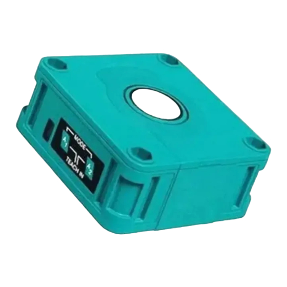
Ultraschallsensor
Abmessungen
15
7,5
Folientastatur
LED-Fenster
16
10
34
Elektrischer Anschluss/Kurven/Zusätzliche Informationen
Charakteristische Ansprechkurve
Abstand Y [m]
1
ebene Platte 100 mm x 100 mm
Normsymbol/Anschluss:
(Version U)
0,5
1
(BN)
+ U
B
2
(WH)
Lerneingang
U
0
5
(GY)
Sync.
4
(BK)
Analogausgang
3
(BU)
-0,5
- U
B
Rundstab, Ø 25 mm
Adernfarben gemäß EN 60947-5-2.
-1
0,0
Steckverbinder V15
2
3
1
5
4
Technische Daten
Allgemeine Daten
Erfassungsbereich
60 ... 2000 mm
Einstellbereich
90 ... 2000 mm
Blindzone
0 ... 60 mm
Normmessplatte
100 mm x 100 mm
Wandlerfrequenz
ca. 175 kHz
Ansprechverzug
ca. 150 ms
Anzeigen/Bedienelemente
LED grün
permanent grün: Power on
LED gelb
permanent: Objekt im Auswertebereich
blinkend: Lernfunktion
LED rot
Normalbetrieb: "Störung"
Lernfunktion: kein Objekt erkannt
Elektrische Daten
Betriebsspannung
U
17 ... 30 V DC , Welligkeit 10 %
B
50 mA
Leerlaufstrom
I
0
Eingang/Ausgang
Synchronisation
bidirektional
0-Pegel: -U
1-Pegel: +4 V...+U
Eingangsimpedanz: > 12 K
Synchronisationsimpuls: 100 s, Synchronisationsimpulspause: 2 ms
Synchronisationsfrequenz
30 Hz
Gleichtaktbetrieb
30/n Hz, n = Anzahl der Sensoren
Multiplexbetrieb
Ausgang
Ausgangstyp
1 Analogausgang 0 ... 10 V
Voreinstellung
Auswertegrenze A1: 90 mm , Auswertegrenze A2: 2000 mm , breite Ultraschallkeule
Auflösung
0,7 mm
Kennlinienabweichung
± 1 % vom Endwert
Reproduzierbarkeit
± 0,1 % vom Endwert
Lastimpedanz
> 1 kOhm
Temperatureinfluss
± 1 % vom Endwert
Umgebungsbedingungen
Umgebungstemperatur
-25 ... 70 °C (-13 ... 158 °F)
Lagertemperatur
-40 ... 85 °C (-40 ... 185 °F)
Mechanische Daten
Anschlussart
Gerätestecker M12 x 1 , 5-polig
Schutzart
IP54
Material
Gehäuse
ABS
Wandler
Epoxidharz/Glashohlkugelgemisch; Schaum Polyurethan, Deckel PBT
Masse
140 g
Normen- und Richtlinienkonformität
Normenkonformität
EN 60947-5-2:2007
Normen
IEC 60947-5-2:2007
EN 60947-5-7:2003
IEC 60947-5-7:2003
Dimensions
5,2
Membrane keys
22
LED window
65
80
Programmierung der Auswertegrenzen
Blindzone
Steigende Rampe
Fallende Rampe
0,5
1,0
1,5
2,0
2,5
3,0
3,5
Abstand X [m]
Nullpunktsgerade
Y
X
A1 = 0
breite Schallkeule
schmale Schallkeule
SS
...+1 V
B
B
15
7.5
5.2
16
10
34
Electrical Connection / Curves / Additional Information
Standard symbol/Connections:
Objektabstand
(version U)
1
(BN)
+ U
B
2
(WH)
Teaching input
U
5
(GY)
A1
A1
A2
Sync.
4
(BK)
Analog output
3
(BU)
- U
B
A1
A2
Core colours in accordance with EN 60947-5-2.
A2
Connector V15
2
3
1
5
4
Technical data
General specifications
Sensing range
Adjustment range
Unusable area
Standard target plate
Transducer frequency
Response delay
Indicators/operating means
LED green
LED yellow
LED red
Electrical specifications
Operating voltage
No-load supply current
Input/Output
Synchronization
Synchronization frequency
Common mode operation
Multiplex operation
Output
Output type
Default setting
Resolution
Deviation of the characteristic curve
Repeat accuracy
Load impedance
Temperature influence
Ambient conditions
Ambient temperature
Storage temperature
Mechanical specifications
Connection type
Protection degree
Material
Housing
Transducer
Mass
Compliance with standards and directives
Standard conformity
Standards
Ultraschallsensor
Ultrasonic sensor
UB2000-F42-U-V15
22
65
80
Characteristic response curve
Distance Y [m]
1
Flat surface 100 mm x 100 mm
0.5
0
-0.5
Round bar, Ø 25 mm
-1
0.0
0.5
1.0
1.5
2.0
2.5
3.0
3.5
Distance X [m]
Y
X
wide sonic beam
narrow sonic beam
60 ... 2000 mm
90 ... 2000 mm
0 ... 60 mm
100 mm x 100 mm
approx. 175 kHz
approx. 150 ms
solid green: Power on
solid: object in evaluation range
flashing: program function
normal operation: "fault"
program function: no object detected
U
17 ... 30 V DC , ripple 10 %
B
SS
50 mA
I
0
bi-directional
0 level -U
...+1 V
B
1 level: +4 V...+U
B
input impedance: > 12 KOhm
synchronization pulse: 100 s, synchronization interpulse period: 2 ms
30 Hz
30/n Hz, n = number of sensors
1 analog output 0 ... 10 V
evaluation limit A1: 90 mm , evaluation limit A2: 2000 mm , wide sound lobe
0.7 mm
± 1 % of full-scale value
± 0.1 % of full-scale value
> 1 kOhm
± 1 % of full-scale value
-25 ... 70 °C (-13 ... 158 °F)
-40 ... 85 °C (-40 ... 185 °F)
Device connector M12 x 1 , 5-pin
IP54
ABS
epoxy resin/hollow glass sphere mixture; foam polyurethane, cover PBT
140 g
EN 60947-5-2:2007
IEC 60947-5-2:2007
EN 60947-5-7:2003
IEC 60947-5-7:2003
Analogue output programmation
Unusable area
Object distance
Rising ramp
A1
A1
A2
Falling ramp
A1
A2
Zero line
A1 = 0
A2

Verwandte Anleitungen für Pepperl+Fuchs UB2000-F42-U-V15


Inhaltszusammenfassung für Pepperl+Fuchs UB2000-F42-U-V15
- Seite 1 Ultraschallsensor Abmessungen Dimensions Ultrasonic sensor UB2000-F42-U-V15 Folientastatur Membrane keys LED-Fenster LED window Elektrischer Anschluss/Kurven/Zusätzliche Informationen Electrical Connection / Curves / Additional Information Programmierung der Auswertegrenzen Charakteristische Ansprechkurve Analogue output programmation Characteristic response curve Blindzone Unusable area Abstand Y [m] Distance Y [m]...
- Seite 2 Adressen / Addresses / Adresses / Direcciónes / Indirizzi Contact Pepperl+Fuchs GmbH · 68301 Mannheim · Germany · Tel. +49 621 776-4411 · Fax +49 621 776-27-4411 · E-mail: fa-info@de.pepperl-fuchs.com Worldwide Headquarters: Pepperl+Fuchs GmbH · Mannheim · Germany · E-mail: info@de.pepperl-fuchs.com USA Headquarters: Pepperl+Fuchs Inc.