
Verwandte Anleitungen für Ecotap DC 60


Inhaltszusammenfassung für Ecotap DC 60
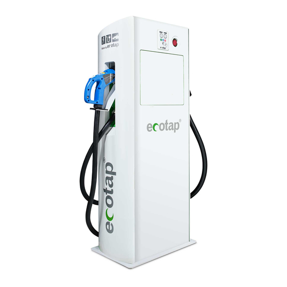
- Seite 1 DC 60 Snellader Handboek | Manual | Anleitung | Manuel Model 2019 YOU’RE IN CHARGE...
- Seite 2 NEDERLANDS...
-
Seite 3: Inhaltsverzeichnis
INHOUDSOPGAVE Inleiding Algemeen Garantie Symbolen in deze handleiding en laadsysteem Apparaat omschrijving Toepassing Accessoires Veiligheidsvoorzieningen Veiligheid Veiligheidsvoorschriften Verplichte controles voor ingebruikname Gebruik / installatie handleiding Openen van de deur Plaatsen van de fundering Kabelinvoer en vastzetten trekontlasting Load Balancer Onderhoud Transport en opslag Storing uitleg Werking en bediening laadsysteem... -
Seite 4: Inleiding
1. INLEIDING Hartelijk dank dat u heeft gekozen voor een DC lader van Ecotap® . Deze handleiding beschrijft de DC lader. In deze handleiding staat belangrijke informatie voor een goede en veilige installatie en gebruik van de DC lader. Het laadstation is ontworpen om voertuigen die voorzien zijn van een mode 4 laadsysteem conform IEC 61851-1 (editie2.0) met stekkersysteem conform... -
Seite 5: Symbolen In Deze Handleiding En Laadsysteem
2.2 Symbolen in deze handleiding en laadsysteem Symbool Betekenis Let op! Belangrijke instructie. Elektrisch gevaar. Bij onderhoud: eerst spanningsvrij maken en diverse meettesten uitvoeren alvorens onderhoud te plegen. Dragen van speciale handschoenen. Spanningsvrij maken van elektrische installatie. Handleiding lezen verplicht. 3. -
Seite 6: Veiligheid
4. VEILIGHEID Lees de volgende veiligheidsvoorschriften goed door voordat u het laadsysteem gaat installeren en in gebruik gaat nemen. 4.1 Veiligheidsvoorschriften Voordat u het laadstation gaat plaatsen maak u de locatie veilig voor omstanders. Laat op deze werkplek NOOIT kinderen toe. Zorg dat NIEMAND die niets met de werkzaamheden heeft te maken op de werkplek komt. -
Seite 7: Gebruik / Installatie Handleiding
√ Controleer of de aardverbinding is gemonteerd op de aansluitklem geheel volgens de Norm NEN1010/EU/35. √ Controleer de stabiliteit van het geplaatste laadstation. √ Controleer of de afdichtingen goed zijn gemonteerd tijdens de montage (IP54). √ Houd de omgeving van de werkplek vrij van obstakels Voordat er spanning op het laadstation wordt gezet is het noodzakelijk om (Ma –... -
Seite 8: Kabelinvoer En Vastzetten Trekontlasting
6.3 Kabelinvoer en vastzetten van de trekontlasting Voedingskabel middels de wartel in de fundering vastzetten. Sluit de aders van de kabel aan op de aanwezige klemmen van de hoofdschakelaar (max. 15 22Nm bout m8 of 30 44Nm bout s10). -
Seite 9: Load Balancer
6.4 Load balancer Indien u het laadstation wilt installeren in combinatie met een load balancer dient u deze op de volgende wijze aan te sluiten in het laadstation. De installatie instructie van het laadstation in de meterkast kunt u vinden in de handleiding van de load balancer zelf. -
Seite 10: Werking En Bediening Laadsysteem
LET OP! Alle werkzaamheden en aanpassingen aan het laadstation dienen minimaal te voldoen aan de NEN1010 10. WERKING EN BEDIENING LAADPUNT Het laadstation is te bedienen met de drukknop of laadpas afhankelijk van het model. Voordat er spanning op het laadstation wordt gezet is het noodzakelijk om contact op te nemen met de back office provider waarvan het telefoon nummer op het laadsysteem vermeld staat zodat het laadstation softwarematig kan worden geactiveerd. -
Seite 11: Technische Specificaties
11. TECHNISCHE SPECIFICATIES AC INPUT Input voltage: 400VAC ± 10% Input frequentie: 50Hz Nominale uitgangsbelasting PF ≥ Power factor: 0.99 Aansluitwaarde: 3 x 100A (Bij lager beschikbaar vermogen kan de lader softwarematig lager worden ingesteld) Input onderspanningsbeveiliging: 255V ±5V Ingang overspanningsbeveiliging: 490V ±5V Ingangsvermogen reductie: 260V ±5V<Vin<304V±5V,... - Seite 12 Bedrijfs- / omgevingstemperatuur: -25° tot 60° Laad temperatuur: - 40°C ~ 85°C Vochtigheid: ≤ 95% RH, zonder condensatie Druk / hoogte: 79kPa~106kPa/2000m FYSIEKE EIGENSCHAPPEN Akoestisch geluid: < 62dB Koeling: Luchtkoeling ventilatoren Afmetingen: 1440 mm x 610 mm x 350 mm Europese normen: EN 61851-1 2011, EN 6185123-2014, CE Materiaal behuizing:...
-
Seite 13: Contactgegevens Leverancier
Ecotap® B.V. behoudt zich het recht voor om zonder voorafgaande kennisgeving de bovenstaande technische gegevens te wijzigen als gevolg van voortgaande, innovatieve ontwikkelingen van het laadstation. De technische gegevens kunnen bovendien van land tot land verschillend zijn. 12. CONTACTGEGEVENS LEVERANCIER Ecotap®... - Seite 14 ENGLISH...
- Seite 15 TABLE OF CONTENTS Introduction General 15.1 Warranty 15.2 Symbols used in this manual Device description 16.1 Application 16.2 Accessories 16.3 Safety device Safety 17.1 Safety instructions Mandatory checks before initial use Operation / installation manual 19.1 Open the door 19.2 Mounting on foundation 19.3 Insert cable and attach strain relief...
-
Seite 16: Introduction
15.1 Warranty The Ecotap® B.V. General Delivery Conditions apply. Ecotap® B.V. cannot be held responsible for injury or damages as a result of the charging station being changed, damaged, converted, or expanded with other components, or if it is not being used in accordance with the specified... -
Seite 17: Symbols Used In This Manual
15.2 Symbols used in this manual and on the charging system Symbol Meaning Pay attention! Important instruction Electrical hazard For maintenance: first disconnect the installation from its power supply and test it to make sure there is no voltage left, before engaging in any maintenance activities Wear special gloves. -
Seite 18: Safety
- Strain relief - Minimum 3.3 mm steel casing - IP54. 17. SAFETY Read the following safety regulations carefully before you install and use the charging station. 17.1 Safety instructions Before you install the charging station, you must make sure the location is safe for all bystanders. -
Seite 19: Operation / Installation Manual
Before the power is connected to the charging station, you must first call Ecotap® B.V. on +31 (0)411 745 020 (Mo – Fr 09:00 to 16:00) so that we can activate its software (this requires the unique charging station number). -
Seite 20: Insert Cable And Attach Strain Relief
19.3 Inserting cable and securing with strain relief Secure the power cable in the foundation using the cable gland. Connect the conductors of the cable to the existing main switch terminals (max. 15 22Nm bolt m8 oder 30 44Nm bolt s10). Below is an overview of the wiring diagram... -
Seite 21: Loadbalancer
19.4 Load balancer If you want to install the charging station in combination with a load balancer you must connect it to the charging station in the following way. The installation instruction of the charging station in the fuse box can be found in the manual of the load balancer itself. -
Seite 22: Resolving Problems
The charging card must be registered in the relevant back- office system. This required registration can also be done during office hours by calling Ecotap® B.V. Tel. +31 (0)411 745 020. Once registration is complete, the charging station can be used with any Electric Transport charging card (EV charging card) or other suitable cards, both mobile and key holder. -
Seite 23: Technical Specifications
24. TECHNICAL SPECIFICATIONS AC INPUT Input voltage: 400VAC ± 10% Input frequency: 50Hz Power factor: Rated output load PF ≥ 0.99 Connection value: 3 x 100A (With a lower available capacity, the charger can be set lower by software) Input under voltage protection: 255V ±5V Input overvoltage protection: 535V ±5V... - Seite 24 - With 2 cars at the same time, distribution 30Kw - 30Kw CONTROL Start-Stop: RFID-card Ethernet (standard) / GPRS-UMTS Network interface: (3G) Push button: Emergency stop button Ecotap® B.V. reserves the right to change technical details due to continual,...
-
Seite 25: Contact Details Supplier
E-mail: info@ecotap.nl 26. EU CONFORMITY STATEMENT (Directive 2014/35/EU, Annex II page 96/369, EMC 2014/30/EU) Ecotap® B.V. Kruisbroeksestraat 23, 5281RV Boxtel, the Netherlands, hereby states that the following charging station meets the requirements of the listed directives and standards. Type: Ecotap® DC 60... - Seite 26 DEUTSCH...
- Seite 27 INHALTSVERZEICHNIS Einleitung Allgemein 28.1 Garantie 28.2 Symbole in diesem Handbuch und der Ladestation Gerätebeschreibung 29.1 Anwendung 29.2 Zubehör 29.3 Sicherheitsvorrichtungen Sicherheit 30.1 Sicherheitsvorschriften Obligatorische Prüfungen vor der Inbetriebnahme Betriebs-/Installationshandbuch 32.1 Öffnen der Tür 32.2 Montage auf dem Fundament 32.3 Kabel einführen und sichern (mit Zugentlastung) 32.4 Load Balancer Wartung...
-
Seite 28: Einleitung
28. ALLGEMEIN 28.1 Garantie Hier gelten die Allgemeinen Lieferbedingungen von Ecotap® B.V. Ecotap® B.V. kann nicht für Personen- oder Sachschäden haftbar gemacht werden, die durch eine modifizierte, beschädigte oder umgerüstete Ladestation verursacht wurden oder durch eine, die mit anderen Bauteilen ausgerüstet wurde oder nicht entsprechend der angegebenen... -
Seite 29: Symbole In Diesem Handbuch Und Der Ladestation
28.2 Symbole in diesem Handbuch und der Ladestation Symbol Bedeutung Achtung! Wichtige Anweisung Elektrische Gefährdung. Während der Wartung: erst von der Stromversorgung trennen und die Spannungsfreiheit prüfen bevor Wartungsarbeiten durchgeführt werden. Tragen Sie spezielle Handschuhe. Elektrische Anlage spannungsfrei schalten Das Lesen des Handbuchs ist Pflicht 29. -
Seite 30: Sicherheit
- Zugentlastungen - Stahlgehäuse mit mindestens 3,3 mm Blechdicke - IP54 30. SICHERHEIT Lesen Sie vor der Installation und dem Betrieb der Ladestation die folgenden Sicherheitsrichtlinien. 30.1 Sicherheitsvorschriften Stellen Sie vor der Platzierung der Ladestation sicher, dass der Ort für Passanten sicher ist. -
Seite 31: Obligatorische Prüfungen Vor Der Inbetriebnahme
31. OBLIGATORISCHE PRÜFUNGEN VOR DER INBETRIEBNAHME Vor der Inbetriebnahme der Ladestation müssen folgende Prüfungen durchgeführt werden. NIEMALS die Ladestation verwenden, wenn eine oder mehr Prüfungen anzeigen, dass die Stromversorgung oder Stabilität der Ladestation nicht den Anforderungen entspricht. Prüfen Sie den Isolationswiderstand zwischen den Phasen nach der Norm DIN VDE 0100-600. -
Seite 32: Kabel Einführen Und Sichern (Mit Zugentlastung)
flach sein. Legen Sie die Wasserwage für das Fundament in die Grube. Die Oberseite des Fundaments muss sich auf Höhe der Oberseite des Bodens / Pflasters befinden. Das Fundament muss dann mit mindestens 2 x 20 kg Schnellbeton verstärkt werden, der in den Ecken des Fundaments anzubringen ist. -
Seite 33: Load Balancer
Übersicht über das Anschlussschema 32.4 Load balancer Wenn Sie die Ladestation in Kombination mit einem Load Balancer installieren möchten, müssen Sie die wie folgt an die Ladestation anschließen. Für die Montageanleitung der Ladestation im Zählerschrank finden Sie die Montageanleitung des Load Balancers im Handbuch zum Load Balancer selbst. -
Seite 34: Wartung
Überprüfen Sie die Anschlüsse der Hauptstromverkabelung und achten Sie auf einen festen Sitz, Siehe Punkt 32.3 Beschädigungen der Ladestation sind durch korrosionsbeständige Lackierung in der richtigen Farbe (Ecotap® Grün RAL 6018 und Weiß RAL 9016) zu überstreichen. Bei Bedarf sollten Zylinderschlösser mit Graphitpulver oder geeignetem Öl geschmiert werden. -
Seite 35: Bedienung Und Funktionsweise Der Ladestation
Die Details des Ladepasses sind allerdings noch im entsprechenden Backoffice System zu registrieren. Diese notwendige Registrierung kann während der Arbeitszeit telefonisch bei Ecotap® B.V. vorgenommen werden (Tel. 0031 (0) 411-745 020). Nach Abschluss der Registrierung kann die Ladestation mit einem Ecotap Ladekarte oder anderen geeigneten Karten, Mobiltelefonen oder Schlüsselanhängern verwendet werden. -
Seite 36: Technische Spezifikationen
37. TECHNISCHE SPEZIFIKATIONEN AC INPUT Eingangsspannung: 400VAC ± 10% Eingangsfrequenz: 50Hz Leistungsfaktor: Ausgangsnennlast PF ≥ 0.99 Anschlusswert: 3 x 100A (Mit einer geringeren verfügbaren Leistung kann das Ladegerät per Software niedriger eingestellt werden) Eingang unter Spannungsschutz: 255V ±5V Eingangsüberspannungsschutz: 535V ±5V 260V ±5V<Vin<304V±5V, Leistungsreduzierung: Lineare Leistung von 100% bis 50%... - Seite 37 Lagertemperatur: - 40°C ~ 85°C Feuchtigkeit: ≤ 95% RH, ohne Kondensation Druck / Höhe: 79kPa~106kPa/2000m PHYSIKALISCHE EIGENSCHAFTEN Akustische Geräusche: < 62dB Kühlung: Luftkühlung Ventilation Maße: 1440 mm x 610 mm x 350 mm Europäische Normen: EN 61851-1 2011, EN 6185123-2014, CE Gehäusematerial: Stahl >3 mm Korrosionsschutz und...
-
Seite 38: Kontaktdaten Des Lieferanten
Ecotap® B.V. behält sich das Recht vor, die oben stehenden technischen Daten infolge der innovativen Weiterentwicklung der Ladestationen ohne vorherige Benachrichtigung zu ändern. Die technischen Daten können außerdem von Land zu Land unterschiedlich sein. 38. KONTAKTDATEN DES LIEFERANTEN Ecotap® B.V. -
Seite 39: Eu-Konformitätserklärung
39. EU-KONFORMITÄTSERKLÄRUNG CE 2019 (Richtlinie 2014/35/EU, Anhang II, S. 96/369, EMC 2014/30/EU) Hiermit erklärt Ecotap® B.V., Kruisbroeksestraat 23, 5281RV Boxtel, Niederlande, dass die folgende Ladestation den Anforderungen der nachfolgend benannten Richtlinien und Normen entspricht. Typ: Ecotap® DC 60 Baujahr: 2019... - Seite 40 FRANÇAIS...
- Seite 41 TABLE DES MATIÈRES Introduction Généralités 41.1 Garantie 41.2 Symboles dans ce mode d’emploi et borne Description de l’appareil 42.1 Application 42.2 Accessoires 42.3 Dispositifs de sécurité Sécurité 43.1 Règles de sécurité Contrôles obligatoires avant la mise en service Manuel d’utilisation / d’installation 45.1 Ouverture de la porte 45.2...
-
Seite 42: Introduction
40. INTRODUCTION Merci d’avoir choisi une borne de recharge DC Ecotap® . Ce mode d’emploi décrit la borne de recharge DC. Ce mode d’emploi contient des informations importantes pour une installation et une utilisation correctes et sûres de la borne de recharge DC. -
Seite 43: Symboles Dans Ce Mode D'emploi Et Borne
41.2 Symboles dans ce mode d’emploi et système de recharge Symbole Signification Attention ! Instruction importante Danger électrique En cas de maintenance : débranchez d’abord l’alimentation électrique et effectuez divers tests de mesure avant d’effectuer la maintenance Portez des gants spéciaux L’installation électrique doit être mise hors tension La lecture du mode d’emploi est obligatoire 42. -
Seite 44: Sécurité
43. SÉCURITÉ Lisez attentivement les instructions de sécurité suivantes avant d’installer et de mettre en service la borne de recharge 43.1 Règles de sécurité Avant d’installer la borne de recharge, assurez-vous que l’endroit est sûr pour les passants. N’autorisez JAMAIS les enfants sur ce lieu de travail. Assurez- vous que RIEN qui n’a rien à... -
Seite 45: Manuel D'utilisation / D'installation
√ Vérifiez que les noyaux sont serrés, voir point 45.3. √ Vérifiez que la prise de terre est entièrement montée sur la borne conformément à la norme NEN1010/EU/35. √ Vérifiez la stabilité de la borne de recharge installée. √ Vérifiez que les joints sont correctement montés lors de l’installation (IP54). -
Seite 46: Entrée De Câble Et Fixation De La Décharge De Traction
45.3 Entrée de câble et fixation de la décharge de traction Fixez le câble d’alimentation dans la base avec l’écrou. Raccordez les fils du câble aux bornes existantes de l’interrupteur principal (15 à 22Nm boulon m8 ou 30 à 44Nm boulon s10 maximum). -
Seite 47: Équilibreur De Charge
45.4 Équilibreur de charge Si vous souhaitez installer la borne de recharge en combinaison avec un équilibreur de charge, vous devez connecter celui-ci à la borne de recharge de la manière suivante. Les instructions d’installation de la borne de recharge dans le compteur se trouvent dans le mode d’emploi de l’équilibreur de charge. -
Seite 48: Explication De Dysfonctionnement
48. EXPLICATION DE DYSFONCTIONNEMENT Si la borne de recharge ne fonctionne pas, contactez directement le back office du fournisseur concerné. N’ouvrez en aucun cas la borne de recharge vous-même! Ceci est potentiellement mortel. Seuls les mécaniciens / installateurs agréés disposant des outils de mesure appropriés peuvent brancher la borne de recharge et l’ouvrir pour la réparer. -
Seite 49: Caractéristiques Techniques
50. CARACTÉRISTIQUES TECHNIQUES ENTRÉE AC Tension d’entrée: 400 VAC ± 10 % Fréquence d’entrée: 50Hz Facteur de puissance: Charge de sortie nominale PF ≥ 0,99 Valeur de connexion: 3 x 100A (avec une puissance disponible plus faible, la borne de recharge peut être réglée plus bas par le logiciel) Protection contre les soustensions 255V ±5V... - Seite 50 Protection contre la surchauffe: à une température > 70 °C ± 4 °C ou < -40 °C ± 4 °C, la borne de recharge s’éteint automatiquement. Fonctionnement / Température - 25 °C à 60°C ambiante: Température de charge: - 40°C ~ 85°C Humidité: ≤...
-
Seite 51: Coordonnées Du Fournisseur
(3G) Bouton-poussoir: Bouton d’arrêt d’urgence Ecotap® B.V. se réserve le droit de modifier les données techniques ci-dessus sans préavis, en raison des développements permanents et innovants de la borne de recharge. En outre, les données techniques peuvent varier d’un pays à l’autre. -
Seite 52: Déclaration De Conformité De L'ue
52. DÉCLARATION DE CONFORMITÉ DE L’UE CE 2019 (Directive 2014/35/UE, Annexe II p. 96/369, CEM 2014/30/UE) Par la présente, Ecotap® B.V. Kruisbroeksestraat 23, 5281RV Boxtel, déclare que la borne de recharge mentionnée ci-dessous est conforme aux exigences des directives et normes mentionnées ci-dessous. - Seite 53 Contact | Kontakt Ecotap B.V. Kruisbroeksestraat 23 5281 RV Boxtel The Netherlands +31(0) 411 210 210 info@ecotap.nl www.ecotap.nl YOU’RE IN CHARGE...