Werbung
Verfügbare Sprachen
Verfügbare Sprachen
Quicklinks
Werbung

Verwandte Anleitungen für Peavey CLASSIC SO/50


Inhaltszusammenfassung für Peavey CLASSIC SO/50
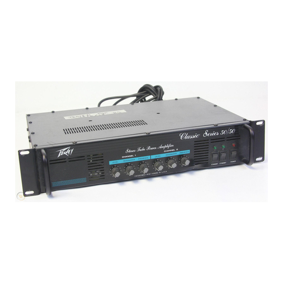
- Seite 1 CLASSIC” SO/50 A L L T U B E P O W E R A M P...
- Seite 2 Intended to alert the user to the presence of uninsulated “dangerous voltage” within the product’s enclosure that may be of sufficient magnitude to constitute a risk of electric shock to persons. Intended to alert the user to the presence of important operating and maintenance (servicing) instruc- tions in the literature accompanying the product.
- Seite 3 POWER SWITCH (1) Depress the switch to the “On” position. The red pilot light (LED) will illuminate indicating power is being supplied to the unit. POWER LED (2) Illuminates when AC power is being supplied to the amp. CHANNEL 1 STANDBY SWITCH (3) Allows channel 1 of amp to be placed in standby or active mode.
- Seite 4 RESONANCE CHANNEL 2 (11) Used to fine tune speaker enclosure low frequency response by varying the damping factor of channel 2 at low frequencies. NOTE: Not operational in mono mode. PRESENCE CHANNEL 2 (12) Used to fine tune speaker enclosure high frequency response by varying the damping factor of channel 2 at high frequencies.
- Seite 5 ( + or -) or until the noise is minimized. NOTE: Should the noise problem continue, consult your Authorized Peavey Dealer, the Peavey Factory, or a qualified service technician. THE GROUND SWITCH IS NOT FUNCTIONAL ON 220/240 VOLT MODELS.
-
Seite 6: Specifications
SPECIFICATIONS Input: Power @ Clipping (Typically): 50 W RMS into 4, 8, and 16 Input impedance, 250K ohms Rated Power: Minimum input level: 1 V RMS, ohms 50 W RMS into 4, 8 and 16 (Continuous sine wave with less 0 dBV ohms, both channels driven than 5% THD, 40 Hz to 20... - Seite 7 MONO APPLICATION USE FULL RANGE OUT PREAMP MONO MODE CLASSIC 50150 INPUT: CH 1 OUTPUT: CH 1, 8 OHMS 100 WATTS 8 OHM CABINET DUAL MONO APPLICATION PREAMP DUAL MODE PATCH INPUTS TOGETHER WITH SHIELDED CABLE CH 1 OUTPUT 16 OHMS CH 2 OUTPUT 16 OHMS , 50 WATTS 16 OHM CABINET...
- Seite 8 PREAMP WITH CROSSOVER CH 1 OUTPUT SET 8 OHMS 5 0 WAlTS ( 8 OHM CABINET 4 OHM CABINET PREAMP STEREO EFX PROCESSOR DUAL MODE CLASSIC !%I/50 CH 1 OUTPUT 16 OHMS CH 2 OUTPUT 16 OHMS 50 WAllS 50 WATTS 16 OHM CABINET 16 OHM CABINET...
- Seite 9 Consulte 10s diagramas de1 panel delantero en la seccih de ingk de este manual. POWER SWITCH (Interruptor de corriente) (1) Oprima el interruptor a la posici6n “hacia dentro” (encendido). La luz roja de1 pilot0 (indicador) se encendera indicando que la unidad estA recibiendo corriente alterna. POWER LED (LED indicador de corriente) (2) Se ilumina cuando el amplificador recibe corriente alterna.
- Seite 10 -13- SPEAKER OUTPUTS CHANNEL 1 (Salidas de altavoces de1 canal 1) (13) Se proporcionan dos salidas de altavoces de % de pulgada. Estos enchufes hembras estin en paralelo. El inter- ruptor de impedancia para el canal 1 selecciona la impedancia total que esti enchufado en la salida de1 canal 1. NOTA: Cuando el interruptor (“mono/stereo”) est.5 en la posici6n estereofdnica utilice 10s ntimeros 16, 8, y 4 que estin arriba de1 interruptor de impedancia de1 canal 1.
- Seite 11 (20) LINE OUTPUT CHANNEL 1 (Salida de linea) La salida de linea proporciona una sefial con control de nivel para impulsar a otros sistemas de altavoces, tipo amplificador de potencia o “esclavo”. LINE OUTPUT CHANNEL 2 (Salida de linea) (21) La salida de linea proporciona una sefial con control de nivel para impulsar a otros sistemas de altavoces, tipo amplificador de potencia o “esclavo”.
- Seite 12 Veuillez vows r6f6rer au “front panel line art” POWER SWITCH (Interrupteur d’alimentation) (1) Mettre l’interrupteur en position “On”. La lampe temoin rouge (DEL) s’illumine indiquant que l’appareil est aliment6 en courant. POWER LED (DEL temoin de mise sous tension) (2) S’allume lorsque l’ampli recoit l’alimentation CA.
- Seite 13 -13- 16 L14A SPEAKER OUTPUTS CHANNEL 1 (Sorties poujr haut-parleurs canal 1) (-13) Deux sorties % N (6,35 nun) pour haur-parleurs sont fournies. Le selecteur d’impedance du canal 1 selec- tionne l’impedance totale branchee a la sortie du canal 1. NOTE: Quand le selecteur (“Mono/Stereo”) est en position stereo, utilisez les nombres 16, 8, et 4 situ&...
- Seite 14 LINE OUTPUT CHANNEL 1 (Sortie ligne) (20) Le niveau du signal present & cette sortie ligne est controle a partir de la commande “Line Output Level”. 11 peut servir a alimenter d’autres systemes d’amplificateur/haut-parleurs asservis. (Voir “Line Output Level”) LINE OUTPUT CHANNEL 2 (Sortie ligne) (21) Le niveau du signal present a cette sortie ligne est controle a partir de la commande “Line Output Level”.
- Seite 15 Siehe diagramm der frontplatte im englischen teil des handbuchs. POWER SWITCH (Netzschalter) (1) Bringen Sie den Schalter auf die ON-Position. Die rote Kontrollampe (LED) leuchtet und zeigt an, dal3 das POWER LED (2) Zeigt die eingeschaltete Netzspannung an. STANDBY SCHALTER KANAL 1 (3) Hiermit wird Kanal 1 des Verstarkers in den Standby- oder Spielbetrieb-Mode versetzt.
- Seite 16 -14- SPEAKER OUTPUTS KANAL 1 (13) Zwei Lautsprecherausgange (Klinkenbuchsen) stehen zur Verftigung. Diese Buchsen sind parallel geschaltet. Der Impedanzwahlschalter fiir Kanal 1 w&h die gesamte Impedanz, die an den Kanal 1 Ausgang angeschlossen ist. MERKE: Wenn der Mono/Stereo-Schalter auf Stereo geschaltet ist die Zahlen 16, 8, und 4 fiber dem Kanal 1 Impedanzwahlschalter verwenden.
- Seite 17 LINE OUTPUT CHANNEL 1 (20) Der Line Output liefer ein Signal mit Pegelregler urn andere Endstufen/Slave Lautsprechersysteme zu betreiben. (Siehe Line Output Level). LINE OUTPUT CHANNEL 2 (21) Der Line Output liefer ein Signal mit Pegelregler urn andere Endstufen/Slave Lautsprechersysteme zu betreiben. (Siehe Line Output Level).
- Seite 18 PEAVEY OO-DAY LIMITED WARRANTY ON TUBES AND METERS If this product contains tubes or meters, Peavey warrants the tubes or meters contained in the product to be free from defects in matenal and workmanship for a period of ninety (90) days from date of purchase; PROVIDED, however, that this limited warranty is extended only to the original retail purchaser and also subject to the conditions, exclusions, and limitations hereinafter set forth.
-
Seite 19: Important Safety Instructions
The user should not attempt to service this equipment. All service work should be done by a qualified service technician. This product should be used only with a cart or stand that is recommended by Peavey Electronics. Exposure to extremely high noise levels may cause a permanent hearing loss. Individuals vary considerably in susceptibility to noise induced hearing loss, but nearly everyone will lose some hearing if exposed to sufficiently intense noise for a sufficient time.