Inhaltsverzeichnis
Werbung
Verfügbare Sprachen
Verfügbare Sprachen
Quicklinks
Werbung
Kapitel
Inhaltsverzeichnis

Verwandte Anleitungen für Glamox FL60


Inhaltszusammenfassung für Glamox FL60
- Seite 1 Strahler mit LED Betriebsanleitung FL60 FL60N (Navy) FL60S (Spot) Glamox Production GmbH & Co. KG Glasower Weg 5, 17166 Teterow, Germany www.glamox.com/gmo Seite 1 von 27 02.02.2016 7179761000 / Index 03 / DCN 21969...
- Seite 2 Die Betriebsanleitung ist vor Einsatz des Produktes sorgfältig zu lesen. GLAMOX BEHÄLT SICH VOR AN DEN BESCHRIEBENEN PRODUKTEN TECHNISCHE ÄNDERUNGEN VORZUNEH- MEN. Seite 2 von 27 02.02.2016 7179761000 / Index 03 / DCN 21969...
-
Seite 3: Inhaltsverzeichnis
Zulässige Anbaulagen ............9 Befestigung ................9 Strahler anschließen ............10 Handhabung der Anschlussklemme ........15 Externer Potentialleiter ............16 Stranginstallation FL60, FL60N .......... 16 Stranginstallation FL60S ............. 17 Wartung und Instandsetzung ..........17 Besondere Sicherheitsvorschriften ........17 Reinigung ................17 ... -
Seite 4: Vorwort
Vorwort Sehr geehrte Leserin, sehr geehrter Leser, diese Betriebsanleitung macht Sie mit dem sicherheitsgerechten Betrieb des Produktes vertraut. Unser Produkt ist nach dem aktuellen Stand der Technik und den anerkannten sicherheitstechnischen Regeln konstruiert und gebaut worden. Dennoch können Gefahren für Personen oder Sachen entstehen, da sich nicht alle Gefahrenstellen vermeiden lassen, wenn die Funktionsfähigkeit erhalten bleiben soll. -
Seite 5: Sicherheit
Um wichtige Informationen hervorzuheben, werden zwei Arten besonderer Hin- weise verwendet: Dieses Zeichen ist neben allen Warnhinweisen zu finden, die im Fließtext auffallen sollen. Zudem ist der Text, wie hier, fett gedruckt. Diese Art von Warnhinweis bedeutet, dass Gefahr für Leben und Gesundheit von Perso- nen besteht. -
Seite 6: Bestimmungsgemäße Verwendung
Bestimmungsgemäße Verwendung Die Betriebssicherheit des Produktes ist nur bei bestimmungsgemäßer Verwen- dung gewährleistet. Deshalb darf es nur für ihre bestimmungsgemäße Verwen- dung eingesetzt werden. Die bestimmungsgemäße Verwendung liegt nur dann vor, wenn der Strahler am mitgelieferten Halter an einer freien vordefinierten Wand oder Decke montiert worden ist. -
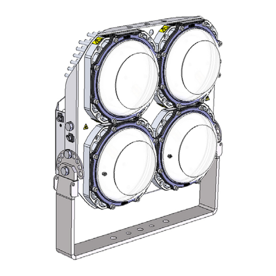
Seite 7: Produktbeschreibung
Gehäuse LED-Modul Material: seewasserbeständige Aluminiumgusslegierung, eloxiert Lampenabdeckung: Material: Polycarbonat Leuchtmittel: Betriebsgerät FL60; FL60N: eigenentwickeltes Betriebsgerät, im LED-Modul integriert Betriebsgerät FL60S im rückseitigen Aluminiumgehäuse integriert Seite 7 von 27 02.02.2016 7179761000 / Index 03 / DCN 21969... -
Seite 8: Betrieb
Kabelverschraubungen: zugelassene Kabelverschraubungen Anschlussklemmen FL60, FL60N: zugelassene Anschlussklemmen Anschlussdose FL60: Material Polycarbonat Anschlussdose FL60N: Material Aluminiumdruckgusslegierung Anschluss FL60S: zugelassene Steckverbindung, Material Polyamid, im Gehäuse montiert, Betrieb Für den störungsfreien Netzbetrieb muss die Eingangsspannung störungsfrei innerhalb der angegebenen Toleranzen liegen. Um Störeinflüsse grundsätzlich auszuschließen, dürfen an der Netzzuleitung für die Strahler keine anderen... -
Seite 9: Installation
Tabelle 2 Temperatursteuerung FL60S4 Die Leistung der Elektronik wird in Abhängigkeit zur Temperatur geregelt. Installation WARNUNG – NICHT UNTER SPANNUNG ÖFFNEN ! An den elektrischen Komponenten des Gerätes liegen lebensgefährliche elektri- sche Spannungen an. WARNUNG – OPTISCHE STRAHLUNG ! Direktes Betrachten der LED kann eine Gefahr für das menschliche Auge bedeuten. -
Seite 10: Strahler Anschließen
Strahler anschließen Vor Beginn der Arbeiten die Energieversorgungsleitung spannungsfrei schalten und gegen unbefugtes Einschalten sichern. Die Anschlussklemme ist für eine Durchverdrahtung geeignet. FL601… bis FL604…Standard Typen Abbildung 3 Anschlussklemme FL601 ..Abbildung 4 Anschlussklemme FL602 ..bis FL604 ..Seite 10 von 27 02.02.2016 7179761000 / Index 03 / DCN 21969... - Seite 11 Abbildung 4a Anschlussklemme FL606… . Seite 11 von 27 02.02.2016 7179761000 / Index 03 / DCN 21969...
- Seite 12 FL60N……Navy Typen Abbildung 5 Anschlussklemme FL60N1 ..Abbildung 6 Anschlussklemme FL60N3 .., FL60N4 .., Seite 12 von 27 02.02.2016 7179761000 / Index 03 / DCN 21969...
- Seite 13 FL60S4…Spot Type mit Steckverbinder Gehäusestecker mit Schutzleiter voreilend Verriegelung und Belegung der Kontakte Abbildung 7 Anschluss-Steckverbindung mit Buchsenteil FL60S4 ..Anschluss über Buchsenteil mit Schraubkontakten. Für starre Leitungen. Für fein- und mehrdrähtige Leiter Aderendhülse verwenden! Abisolierlänge 8,0 mm, Schraubendreher PZ1;...
- Seite 14 Im Falle eines Sternnetzes sind die Strahler wie folgt an das Netz anzuschließen: = Phase - Klemmstellen (1) = Neutralleiter - Klemmstellen (2) = Schutzleiter - Klemmstellen (3) Im Falle eines Deltanetzes sind die Strahler wie folgt an das Netz anzuschließen: ...
-
Seite 15: Handhabung Der Anschlussklemme
Handhabung der Anschlussklemme FL60, FL60N Eindrähtige Leitungen lassen sich ohne die Verwendung von Werkzeug kontak- tieren. Abbildung 9 Kontaktieren ohne die Verwendung von Werkzeug Mehrdrähtige Leitungen oder Leitungen mit kleinen Aderquerschnitten lassen sich unter Verwendung eines Schraubendrehers kontaktieren. Abbildung 10 Kontaktieren mittels Schraubendrehers Seite 15 von 27 02.02.2016... -
Seite 16: Externer Potentialleiter
Querschnitten von bis zu 6 mm² angeschlossen werden. Abbildung 11 Externer Potentialleiteranschluss Stranginstallation FL60, FL60N Die Typen FL60… und FL60N… sind mit zwei Kabelverschraubungen und für eine Durchverdrahtung ausreichender Anzahl an Klemmstellen ausgestattet. Somit besteht die Möglichkeit der Installation in einem Strang. In der Anschluss- dose entsteht durch die eingeführten Leitungen und die Übergangswiderstände... -
Seite 17: Stranginstallation Fl60S
Stranginstallation FL60S Der Strahler FL60S… ist ab Werk mit einer 3-poligen Steckverbindung ausgestattet. Für Durchverdrahtung beim Kundendienst den Steckverbinder, RST-Doppelanschluss anfragen. Nennstrom Gerätestecker montiert: 10 A Interne Betriebselektronik ist ausgestattet mit: Überspannungsschutz, Überstromschutz. Wartung und Instandsetzung Besondere Sicherheitsvorschriften Die Einhaltung der in diesem Kapitel beschriebenen Wartungs- und In- standsetzungsarbeiten gehört zur bestimmungsgemäßen Verwendung des Strahlers. -
Seite 18: Wartung
Wartung Dieses Produkt ist wartungsarm ausgelegt. Die im Folgenden genannten Prüfun- gen sind regelmäßig durchzuführen, um die Sicherheit dauerhaft zu gewährleis- ten. Die Wartungsintervalle sind abhängig von den Umgebungsbedingungen und sind vom Anlagenbetreiber zu definieren. Prüfung auf Maßnahme Lampenabdeckung Beschädigungen und Risse Modul auswechseln Kabelverschraubung Porösität des Dichringes am... -
Seite 19: Kundendienst
Tabelle 5 Störungsbeseitigung Kundendienst Der Kundendienst der Glamox Production GmbH & Co. KG steht Ihnen bei der Bestellung von Ersatzteilen, für Wartungs- und Reparaturarbeiten sowie bei Problemen und Fragen zur Verfügung. Die Anschrift lautet: Glamox Production GmbH & Co. KG... -
Seite 20: Technische Daten
0,96 A Spannung: FL60.0 .., FL60N ..230 V ±10% 50/60 Hz FL60.1 .., FL60N.1 ..120 V ±10% 50/60 Hz FL60.2 .., FL60N.2 ..254 V ±10% 50/60 Hz FL60S4 . - Seite 21 I (gem. EN 60598) UV – beständig: Seewasserbeständig: Vibrationsgeprüft: Umgebungstemperatur: FL60 .., FL60N ..- 45°C ... + 55°C FL60S ..- 30°C … +45°C Gewicht: FL601 ..
-
Seite 22: Bestellnummern
Bestellnummern Strahlbreite Type Spannung mittel breit FL60100XXX FL60101XXX FL60102XXX 230 V FL60N100XX FL60N101XX FL60N101XX FL60111XXX FL60112XXX 120 V FL60110XXX FL60N111XX FL60N112XX 254 V FL60120XXX FL60121XXX FL60122XXX 230 V FL60200XXX FL60201XXX FL60202XXX 120 V FL60210XXX FL60211XXX FL60212XXX 254 V FL60220XXX FL60221XXX FL60222XXX FL60300XXX FL60301XXX... - Seite 23 Strahlbreite Type Spannung mittel breit 230 V FL60600XXX FL60601XXX FL60602XXX 120 V FL60610XXX FL60611XXX FL60612XXX 254 V FL60620XXX FL60621XXX FL60622XXX Strahlbreite Spannung Spot ---- ---- 230 V FL60S400XX -------------- -------------- Tabelle 6: Bestellnummern (XXX = laufende Zählnummer) Seite 23 von 27 02.02.2016 7179761000 / Index 03 / DCN 21969...
-
Seite 24: Anziehdrehmomente
Anziehdrehmomente Anzieh- Größe drehmoment Modul 7 Nm Strahler am Halter FL601, FL60N1 FL602, FL603, 35 Nm FL604, FL606, FL60S FL60N2, FL60N3, FL60N4 Seite 24 von 27 02.02.2016 7179761000 / Index 03 / DCN 21969... - Seite 25 Anzieh- Größe drehmoment Strahler 60 Nm Deckel für Anschlussdose FL60: 0,5 Nm FL60N: 7 Nm FL60S: 7 Nm Anschlussdose FL60: 2 Nm FL60N: 7 Nm FL60S: 7 Nm Seite 25 von 27 02.02.2016 7179761000 / Index 03 / DCN 21969...
- Seite 26 Anzieh- Größe drehmoment Potentialleiter 7,2 Nm Tabelle 7 Anziehdrehmomente für Befestigungsschrauben Seite 26 von 27 02.02.2016 7179761000 / Index 03 / DCN 21969...
- Seite 27 Seite 27 von 27 02.02.2016 7179761000 / Index 03 / DCN 21969...
- Seite 54 Page 27 of 27 02.02.2016 7179761000/ Index 03 / DCN 21969...