
Verwandte Anleitungen für Bicker UPSI-2406DP1

Inhaltszusammenfassung für Bicker UPSI-2406DP1
- Seite 1 Deutsch English UPSI-2406DP1 Benutzerhandbuch UPSI-2406DP2 User Manual UPSI-1208DP2 UPSI-SYSTEM DIN-RAIL Bicker Elektronik GmbH Ludwig-Auer-Straße 23 86609 Donauwörth · Germany...
-
Seite 2: Technical Data Upsi-2406Dp1
UPSI-2406DP1 | UPSI-2406DP2 | UPSI-1208DP2 I. Technical Data UPSI-2406DP1 24 V DC / 3 A Te c h n i c a l D a t a Input voltage 24 V DC (22.5…32 V) Input current 5 A max. Output voltage Normal mode: V –... - Seite 3 UPSI-2406DP1 | UPSI-2406DP2 | UPSI-1208DP2 Product specific data Shutdown detection Via load sensor Reboot function Reboot function and time can be configured by software Load sensor Configurable via UPSI HID-Battery-Parameter software (download at www.bicker.de) UPS shuts down after 15 sec, if connected load decreases below set...
-
Seite 4: Technical Data Upsi-2406Dp2
UPSI-2406DP1 | UPSI-2406DP2 | UPSI-1208DP2 II. Technical Data UPSI-2406DP2 24 V DC / 4.25 A Te c h n i c a l D a t a Input voltage 24 V DC (22.5…32 V) Input current 5.15 A max. Output voltage Normal mode: V –... - Seite 5 UPSI-2406DP1 | UPSI-2406DP2 | UPSI-1208DP2 Product specific data Shutdown detection Via load sensor Reboot function Reboot function and time can be configured by software Load sensor Configurable via UPSI HID-Battery-Parameter software (download at www.bicker.de) UPS shuts down after 15 sec, if connected load decreases below set...
-
Seite 6: Technical Data Upsi-1208Dp2
UPSI-2406DP1 | UPSI-2406DP2 | UPSI-1208DP2 III. Technical Data UPSI-1208DP2 12 V DC / 7 A Te c h n i c a l D a t a Input voltage 12 V DC (11.5…16 V) Input current 8.8 A max. Output voltage Normal mode: V –... - Seite 7 UPSI-2406DP1 | UPSI-2406DP2 | UPSI-1208DP2 Product specific data Shutdown detection Via load sensor Reboot function Reboot function and time can be configured by software Load sensor Configurable via UPSI HID-Battery-Parameter software (download at www.bicker.de) UPS shuts down after 15 sec, if connected load decreases below set...
-
Seite 8: Drawing
UPSI-2406DP1 | UPSI-2406DP2 | UPSI-1208DP2 IV. Drawing UPSI-2406DP1 / UPSI-2406DP2 / UPSI-1208DP2 Tolerance ±0.5 mm 9 mm 100 mm 63 mm UPSI DC UPS... -
Seite 9: Overview Emc Test Results
UPSI-2406DP1 | UPSI-2406DP2 | UPSI-1208DP2 V. Overview of EMC test results – Emission Emission Regulation Test result Class Conducted emission; EN 55016-2-1 The margin for DC power power supply lines connections were passed. (150 kHz – 30 MHz) Radiated emission... -
Seite 10: Inhaltsverzeichnis
UPSI-2406DP1 | UPSI-2406DP2 | UPSI-1208DP2 Technical Data UPSI-2406DP1....................2 Technical Data UPSI-2406DP2....................4 III. Technical Data UPSI-1208DP2....................6 Drawing .............................. 8 Overview EMC test results ......................9 Produkt- und Funktionsbeschreibung UPSI-2406DP1, UPSI-2406DP2, UPSI-1208DP2 ..............12 Description of product and function description UPSI-2406DP1, UPSI-2406DP2, UPSI-1208DP2 ..............28... - Seite 11 UPSI-2406DP1 | UPSI-2406DP2 | UPSI-1208DP2 Ladezeit ............................22 Charging time ..........................38 Verpolung / Überlast / Kurzschluss ..................22 Reverse polartiy / Overload / Short circuit ................38 Überbrückungszeiten (Backup times) ...................22 Backup times ..........................38 Verhalten bei Überschreiten der maximalen Pufferzeiten ..........23 Behavior in case of exceeding maximum backup time ............39 Batteriestart .............................23...
-
Seite 12: Produkt- Und Funktionsbeschreibung
Dieses Handbuch soll den Anwender mit dem Produkt samt dessen Komponenten und Eigenschaften vertraut machen und möglichst vollständige und genaue Informationen dazu liefern. Für mögliche vorhandene Fehler kann Bicker Elektronik jedoch keine Haftung übernehmen. Hinweise hierzu, Verbesserungsvorschläge und Kritik werden jederzeit sehr gerne entgegengenommen. -
Seite 13: Bestimmungsgemäße Verwendung - Beschreibung
UPSI-2406DP1 | UPSI-2406DP2 | UPSI-1208DP2 3 Bestimmungsgemäße Verwendung – Beschreibung Dieses Gerät ist primär für den Einsatz auf der Hutschiene bestimmt und für den pro- fessionellen Einsatz in Bereichen wie industrieller Steuerungs-, Kommunikations- und Messtechnik entwickelt. Es darf nicht in Vorrichtungen oder Anlagen verwendet werden, bei denen eine Fehlfunktion zu schweren Verletzungen führt oder Menschenleben... -
Seite 14: Konvektion Und Einbaulage
UPSI-2406DP1 | UPSI-2406DP2 | UPSI-1208DP2 5 Konvektion und Einbaulage Es sollten keine Lüftungslöcher durch andere, benachbarte Komponenten verdeckt sein. Für diese DIN-Rail-Versionen ist eine senkrechte Montage auf eine waagerechte Schiene (Hutschienen nach EN 60715) empfehlenswert, um die bestmögliche Konvektion der USV zu erreichen. Eine andere Einbaulage ist möglich, ein Betrieb bis +70 °C Umgebungstemperatur kann dadurch aber nicht mehr gewährleistet werden. - Seite 15 UPSI-2406DP1 | UPSI-2406DP2 | UPSI-1208DP2 Hutschienenmontage und Hutschienenprofile nach EN 60715 Nach unten drücken ...
-
Seite 16: Anschlussbeschreibung
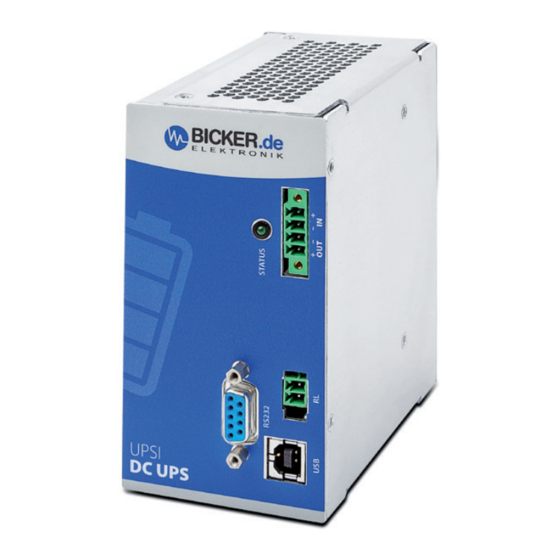
UPSI-2406DP1 | UPSI-2406DP2 | UPSI-1208DP2 6 Anschlussbeschreibung EINGANG & AUSGANG Vin + Vin – Vout – Vout + – – RELAIS-ANSCHLUSS Schließerkontakt: Bei Netzunterbrechung ist Schalter geschlossen (= 0 Ω ). USB-ANSCHLUSS USB Buchse Typ B RS232 DSUB9 SIGNAL MAINBOARD... -
Seite 17: Dimensionierung Der Vorgeschalteten Stromversorgung
Es ist darauf zu achten, dass die Quelle korrekt dimensioniert ist und genug Strom liefert, um den Ladevorgang und die Funktion der Applikation zu garantieren. Die Eingangsspannung bei der UPSI-2406DP1 und UPSI-2406DP2 muss hierfür zwischen 22,5 V und 29 V betragen, bei der UPSI-1208DP2 zwischen 11,5 V und 16 V. Die UPSI redu- ziert je nach Last den Ladestrom. -
Seite 18: Inbetriebnahme
UPSI-2406DP1 | UPSI-2406DP2 | UPSI-1208DP2 8 Inbetriebnahme Es muss sichergestellt sein, dass die USV ordnungsgemäß verbaut ist. Durch das Anschließen der Versorgungsspannung: Wird an den Eingangs klemmen eine Spannung größer als 11,5 V für die UPSI-1208 DP2 und größer als 22,5 V für die UPSI- 2406DP1 / UPSI-2406DP2 angeschlossen, wird der Energieträger abgefragt und übermittelt... - Seite 19 UPSI-2406DP1 | UPSI-2406DP2 | UPSI-1208DP2 Bei Verwendung der Windows® Software zum Herunterfahren des Systems muss folgende Einstellung sichergestellt werden: Systemsteuerung >> Alle Systemsteuerungselemente >> Energieoptionen Auswählen, was beim Drücken des Netzschalters geschehen soll > > Beim Drücken des Netzschalters: Herunterfahren...
-
Seite 20: Anschlussplan
UPSI-2406DP1 | UPSI-2406DP2 | UPSI-1208DP2 9 Anschlussplan 63 mm – – RELAIS RS232 für individuelle Verwendung D Sub 9 UPSI DC UPS ANSCHLUSS-REIHENFOLGE 1. APPLIKATION (V 2. DC-QUELLE (V 3. RELAIS / USB / RS232 Abbau-Reihenfolge umgekehrt zum Anschluss! – ACHTUNG! 1. -
Seite 21: Übersicht Stecker / Gegenstecker Mit Bezeichnung / Lieferumfang
CONNECTOR PART NO. COUNTERPART NO. Vin/out WE691325310004 WE691364300004 Relais WE691305140002 WE691304130002 WE61400416121 USB Typ B Stecker RS232 D-Sub9 Female D-Sub 9 Male Lieferumfang Menge Beschreibung 1x Gerät UPSI-2406DP1 oder UPSI-2406DP2 oder UPSI-1208DP2 - DC USV connector counterpart Relay connector counterpart... -
Seite 22: Ladezeit
UPSI-2406DP1 | UPSI-2406DP2 | UPSI-1208DP2 11 Ladezeit Die Ladezeiten sind abhängig vom Energiespeicher, der Eingangsspannung und dem Laststrom. 12 Verpolung / Überlast / Kurzschluss Das Gerät ist gegen Verpolung bei Inbetriebnahme (Gerät aus, nicht aktiv) geschützt. Befindet sich das Gerät im laufenden Backup-Betrieb, ist kein Verpolschutz gegeben. Im Falle eines zu hohen Stromes für eine Dauer länger als 3s bzw. -
Seite 23: Verhalten Bei Überschreiten Der Maximalen Pufferzeiten
UPSI-2406DP1 | UPSI-2406DP2 | UPSI-1208DP2 14 Verhalten bei Überschreiten der maximalen Pufferzeiten Beim Überschreiten der gegebenen Überbrückungszeiten wird der Ausgang anhand der Entladespannung des entsprechenden Speichers getrennt (Tiefentladeschutz). Bei den Superkondensatoren, die nicht empfindlich auf eine Tiefentladung reagie- ren, wurde eine Schwelle festgelegt, die durch den Strom begrenzt wird. Je nied- riger die Spannung, desto höher der Strom an den Kondensatoren bei konstanter... -
Seite 24: Status Led
UPSI-2406DP1 | UPSI-2406DP2 | UPSI-1208DP2 16 Status LED 1 x blinken, Pause 1,5s Status: Batteriestart 2 x blinken, Pause 1,5s Status: Es wird Kapazität zum Starten benötigt, Zustand Laden 3 x blinken, Pause 1,5s Status Herunterfahren: Warten bis System herunter-... -
Seite 25: Software
UPSI-2406DP1 | UPSI-2406DP2 | UPSI-1208DP2 17 Software Informationen zur Software und der Command List finden Sie im Handbuch zur UPSI- 2406(D). 18 Empfehlungen für eine lange Lebensdauer des USV-Systems Supercaps haben kein tatsächliches „End of Life“ (EOL). Über die Zeit verringert sich die Kapazität und der ESR (Ersatzserienwiderstand) erhöht sich. -
Seite 26: Haftungsausschluss
Unterschreitung des Schwellwertes kommen und ein unbeabsichtigter Power Fail ausgelöst werden. Die Spannung bei maximaler Last direkt am Eingang des Gerätes darf 11,5 V (UPSI-1208DP2) bzw. 22,5 V (UPSI-2406DP1 / UPSI-2406DP2) nicht unterschreiten. Auch nach dem Trennen der Versorgung läuft das Gerät für einige Zeit nach Unterschreitung des Lastsensors weiter (Einstellung eines Schwellwerts für den... - Seite 27 UPSI-2406DP1 | UPSI-2406DP2 | UPSI-1208DP2 WARNUNG! Missachtung nachfolgender Punkte kann einen elektrischen Schlag, Brände, schwere Unfälle oder Tod zur Folge haben. 1. Auf eine ordnungsgemäße und fachgerechte Verdrahtung muss geachtet werden. 2. Das Gerät darf weder Feuer noch Temperaturen außerhalb der Spezifikation ausgesetzt werden.
-
Seite 28: Description Of Product And Function Description
1 Description of product and function description of UPSI-2406DP1, UPSI-2406DP2 and UPSI-1208DP2 The UPSI-2406DP1, UPSI-1208DP2 and UPSI-2406DP2 (hereinafter called UPS) are DC/DC UPS systems with numerous digital features and high performance. The UPS combines die UPSI-1208/2406 with a storage medium (Li-Ion/Supercap). -
Seite 29: Intended Use
UPSI-2406DP1 | UPSI-2406DP2 | UPSI-1208DP2 3 Intended use This device is primary built for being mounted on a DIN Rail and is intended for profes- sional use in applications such as industrial control, communication and measurement technology. It must not be used in devices or equipment where a malfunction will cause serious injury or endanger human life. -
Seite 30: Convection And Installation Position
UPSI-2406DP1 | UPSI-2406DP2 | UPSI-1208DP2 5 Convection and installation position Do not cover any ventilation holes by adjacent components. For DIN rail versions, vertical mounting on a horizontal rail (DIN rails according to EN 60715) is recommended in order to achieve the best possible convection of the UPS. Another mounting position is possi- ble, but operation up to +70 °C ambient temperature can not be guaranteed. - Seite 31 UPSI-2406DP1 | UPSI-2406DP2 | UPSI-1208DP2 DIN-Rail mounting and DIN-Rail profile according to EN 60715 Press down ...
-
Seite 32: Description Of Connectors
UPSI-2406DP1 | UPSI-2406DP2 | UPSI-1208DP2 6 Description of connectors INPUT & OUTPUT Vin + Vin – Vout – Vout + – – RELAIS CONNECTION Make contact (NO): When input power is interrupted, the contact is closed (= 0 Ω ). -
Seite 33: Dimensioning The Upstream Power Supply
The input voltage for the UPSI-2406DP1 and UPSI-2406DP2 must be between 22.5 V and 29 V, for the UPSI- 1208DP2 between 11.5 V and 16 V. The UPSI reduces its charging current depending on the load. -
Seite 34: Initial Operation
Via connection to upstream power supply: When an input voltage higher than 11.5 V (UPSI-1208DP2) respectively 22.5 V (UPSI-2406DP1 / UPSI-2406DP2) is connected to the in- put terminals, the energy storage medium gets queried and transmits its data. The UPS sets an appropriate charging end voltage and clears the pack via System Present signal (X11). - Seite 35 UPSI-2406DP1 | UPSI-2406DP2 | UPSI-1208DP2 When using the Windows® Software to shut down the system, make sure that the following settings are done: Control Panel > > System and Security >> Power Options Choose what the power buttons do >> When I press the power button: Shut down...
-
Seite 36: Connecting Diagram
UPSI-2406DP1 | UPSI-2406DP2 | UPSI-1208DP2 9 Connection 63 mm – – RELAIS RS232 for individual use D Sub 9 UPSI DC UPS CONNECTING ORDER 1. APPLICATION (V 2. DC SOURCE (V 3. RELAIS / USB / RS232 Dismantling order reverse to connection! –... -
Seite 37: Overview Connecter / Counterpart With Part No. / Scope Of Delivery
PART NO. COUNTERPART NO. Vin/out WE691325310004 WE691364300004 Relais WE691305140002 WE691304130002 WE61400416121 USB Type B connector RS232 D-Sub9 Female D-Sub 9 Male Scope of delivery Quantity Description 1x device UPSI-2406DP1 or UPSI-2406DP2 or UPSI-1208DP2 - DC USV connector counterpart Relay connector counterpart... -
Seite 38: Charging Time
UPSI-2406DP1 | UPSI-2406DP2 | UPSI-1208DP2 11 Charging time Charging times depend on storage medium, input voltage and the load current. 12 Reverse polarity / Overload / Short circuit The device is protected against reverse polarity at initial operation (device off, not active). -
Seite 39: Behaviour In Case Of Exceeding Maximum Backup Time
UPSI-2406DP1 | UPSI-2406DP2 | UPSI-1208DP2 14 Behaviour in case of exceeding maximum backup time When the given buffering times are exceeded, the output is separated on the basis of the discharge voltage of the corresponding storage medium (total discharge protection). -
Seite 40: Status Led
UPSI-2406DP1 | UPSI-2406DP2 | UPSI-1208DP2 16 Status LED 1 x flash, pause 1,5s Status: Battery start 2 x flash, pause 1,5s Status: Capacity for start is required, state charging 3 x flash, pause 1,5s Status shutdown: Waiting for shutdown completion... -
Seite 41: Software
UPSI-2406DP1 | UPSI-2406DP2 | UPSI-1208DP2 17 Software Information about the Software and the Command List can be found in the user's manual of the UPSI-2406(D). 18 Recommendations for a long UPS service life Supercaps do not have an actual "End of Life" (EOL). Over time, the capacity decreases and the ESR (equivalent series resistance) increases. -
Seite 42: Disclaimer
UPSI-2406DP1 | UPSI-2406DP2 | UPSI-1208DP2 21 Disclaimer We, the Bicker Elektronik GmbH, have checked the contents of this document for com- pliance with the hardware and software described. Nevertheless, deviations can not be ruled out, so we assume no liability for the complete agreement. The information in this publication is checked regularly, necessary corrections are included in the updated versions. - Seite 43 UPSI-2406DP1 | UPSI-2406DP2 | UPSI-1208DP2 WARNING! Disregarding of following issues can result in electric shock, fire, serious injury or death. 1. Care must be taken to ensure proper and professional wiring. 2. The battery pack must not be exposed to fire and temperatures outside the specification.
- Seite 44 Bicker Elektronik GmbH Ludwig-Auer-Straße 23 86609 Donauwörth · Germany Tel. +49 (0) 906 70595-0 +49 (0) 906 70595-55 Irrtümer und technische Änderungen vorbehalten. Windows® ist ein eingetragenes Warenzeichen der Firma Microsoft Corp. E-Mail info@bicker.de Subject to errors and technical modifications.