Herunterladen Inhalt Inhalt Diese Seite drucken
ASROCK Q170M vPro Handbuch
Vorschau ausblenden Andere Handbücher für Q170M vPro:

Werbung

Verfügbare Sprachen
  • DE

Verfügbare Sprachen

  • DEUTSCH, seite 28
Version 1.0
Published June 2015
Copyright©2015 ASRock INC. All rights reserved.
Copyright Notice:
No part of this documentation may be reproduced, transcribed, transmitted, or
translated in any language, in any form or by any means, except duplication of
documentation by the purchaser for backup purpose, without written consent of
ASRock Inc.
Products and corporate names appearing in this documentation may or may not
be registered trademarks or copyrights of their respective companies, and are used
only for identification or explanation and to the owners' benefit, without intent to
infringe.
Disclaimer:
Specifications and information contained in this documentation are furnished for
informational use only and subject to change without notice, and should not be
constructed as a commitment by ASRock. ASRock assumes no responsibility for
any errors or omissions that may appear in this documentation.
With respect to the contents of this documentation, ASRock does not provide
warranty of any kind, either expressed or implied, including but not limited to
the implied warranties or conditions of merchantability or fitness for a particular
purpose.
In no event shall ASRock, its directors, officers, employees, or agents be liable for
any indirect, special, incidental, or consequential damages (including damages for
loss of profits, loss of business, loss of data, interruption of business and the like),
even if ASRock has been advised of the possibility of such damages arising from any
defect or error in the documentation or product.
This device complies with Part 15 of the FCC Rules. Operation is subject to the following
two conditions:
(1) this device may not cause harmful interference, and
(2) this device must accept any interference received, including interference that
may cause undesired operation.
CALIFORNIA, USA ONLY
The Lithium battery adopted on this motherboard contains Perchlorate, a toxic substance
controlled in Perchlorate Best Management Practices (BMP) regulations passed by the
California Legislature. When you discard the Lithium battery in California, USA, please
follow the related regulations in advance.
"Perchlorate Material-special handling may apply, see www.dtsc.ca.gov/hazardouswaste/
perchlorate"
ASRock Website: http://www.asrock.com

Werbung

Inhaltsverzeichnis
loading

Inhaltszusammenfassung für ASROCK Q170M vPro

  • Seite 1 (including damages for loss of profits, loss of business, loss of data, interruption of business and the like), even if ASRock has been advised of the possibility of such damages arising from any defect or error in the documentation or product.
  • Seite 2 The terms HDMI™ and HDMI High-Definition Multimedia Interface, and the HDMI logo are trademarks or registered trademarks of HDMI Licensing LLC in the United States and other countries.
  • Seite 3: Motherboard-Layout

    Q170M vPro Motherboard Layout CPU_FAN1 ATX12V1 USB 3.0 T: USB7 B: USB8 USB 3.0 Top: T: USB3 RJ-45 B: USB4 CMOS CHA_FAN1 Battery Q170M vPro PCIE1 PCI Express 3.0 CHA_FAN2 PCIE2 Intel Q170 PCIE3 RoHS PCIE4 128Mb Audio BIOS CODEC...
  • Seite 4 No. Description ATX 12V Power Connector (ATX12V1) CPU Fan Connector (CPU_FAN1) 2 x 288-pin DDR4 DIMM Slots (DDR4_A1, DDR4_B1) 2 x 288-pin DDR4 DIMM Slots (DDR4_A2, DDR4_B2) ATX Power Connector (ATXPWR1) SATA3 Connector (SATA3_0) SATA3 Connector (SATA3_1) USB 3.0 Header (USB3_5_6) Chassis Fan Connector (CHA_FAN2) SATA3 Connector (SATA3_2) SATA3 Connector (SATA3_3)
  • Seite 5 Q170M vPro I/O Panel No. Description No. Description PS/2 Mouse/Keyboard Port Microphone (Pink) D-Sub Port Central / Bass (Orange) LAN RJ-45 Port* USB 3.0 Ports (USB3_34) Side Speaker (Gray) USB 3.0 Ports (USB3_7_8) Rear Speaker (Black) HDMI Port Line In (Light Blue)
  • Seite 6 * There are two LEDs on each LAN port. Please refer to the table below for the LAN port LED indications. ACT/LINK LED SPEED LED LAN Port Activity / Link LED Speed LED Status Description Status Description No Link 10Mbps connection Blinking Data Activity Orange...
  • Seite 7: Chapter 1 Introduction

    If you require technical support related to this mother- board, please visit our website for specific information about the model you are using. You may find the latest VGA cards and CPU support list on ASRock’s website as well. ASRock website http://www.asrock.com.
  • Seite 8: Specifications

    1.2 Specifications • Micro ATX Form Factor Platform • Solid Capacitor design • High Density Glass Fabric PCB • Supports 6 Generation Intel® Core i7/i5/i3/Pentium®/ Celeron® Processors (Socket 1151) • Digi Power design • 6 Power Phase design • Supports Intel® Turbo Boost 2.0 Technology • Intel®...
  • Seite 9 • 1 x D-Sub Port • 1 x DVI-D Port • 1 x HDMI Port • 6 x USB 3.0 Ports (Supports ESD Protection (ASRock Full Spike Protection)) • 1 x RJ-45 LAN Port with LED (ACT/LINK LED and SPEED LED) • HD Audio Jacks: Side Speaker / Rear Speaker / Central /...
  • Seite 10 • 1 x Front Panel Audio Connector • 1 x USB 2.0 Header (Supports 2 USB 2.0 ports) (Supports ESD Protection (ASRock Full Spike Protection)) • 1 x USB 3.0 Header (Supports 2 USB 3.0 ports) (Supports ESD Protection (ASRock Full Spike Protection)) • 128Mb AMI UEFI Legal BIOS with multilingual GUI sup-...
  • Seite 11 * To install Windows® 7 OS, a modified installation disk with xHCI drivers packed into the ISO file is required. Please refer to page 141 for more detailed instructions. * For the updated Windows® 10 driver, please visit ASRock’s website for details: http://www.asrock.com • FCC, CE, WHQL Certifica- • ErP/EuP Ready (ErP/EuP ready power supply is required)
  • Seite 12: Chapter 2 Installation

    Chapter 2 Installation This is an ATX form factor motherboard. Before you install the motherboard, study the configuration of your chassis to ensure that the motherboard fits into it. Pre-installation Precautions Take note of the following precautions before you install motherboard components or change any motherboard settings.
  • Seite 13: Installing The Cpu

    Q170M vPro 2.1 Installing the CPU 1. Before you insert the 1151-Pin CPU into the socket, please check if the PnP cap is on the socket, if the CPU surface is unclean, or if there are any bent pins in the socket. Do not force to insert the CPU into the socket if above situation is found.
  • Seite 15 Q170M vPro Please save and replace the cover if the processor is removed. The cover must be placed if you wish to return the motherboard for after service.
  • Seite 16 2.2 Installing the CPU Fan and Heatsink...
  • Seite 17 Q170M vPro 2.3 Installing Memory Modules (DIMM) This motherboard provides four 288-pin DDR4 (Double Data Rate 4) DIMM slots, and supports Dual Channel Memory Technology. 1. For dual channel configuration, you always need to install identical (the same brand, speed, size and chip-type) DDR4 DIMM pairs.
  • Seite 19 Q170M vPro 2.4 Expansion Slots (PCI Express Slots) There are 4 PCI Express slots on the motherboard. Before installing an expansion card, please make sure that the power supply is switched off or the power cord is unplugged. Please read the documentation of the expansion card and make necessary hardware settings for the card before you start the installation.
  • Seite 20 2.5 Jumpers Setup The illustration shows how jumpers are setup. When the jumper cap is placed on the pins, the jumper is “Short”. If no jumper cap is placed on the pins, the jumper is “Open”. The illustration shows a 3-pin jumper whose pin1 and pin2 are “Short” when a jumper cap is placed on these 2 pins.
  • Seite 21 Q170M vPro 2.6 Onboard Headers and Connectors Onboard headers and connectors are NOT jumpers. Do NOT place jumper caps over these headers and connectors. Placing jumper caps over the headers and connectors will cause permanent damage to the motherboard. System Panel Header...
  • Seite 22 Chassis Intrusion and Please connect the SPEAKER DUMMY Speaker Header chassis intrusion and the DUMMY (7-pin SPK_CI1) chassis speaker to this (see p.1, No. 15) header. SIGNAL DUMMY Serial ATA3 Connectors These six SATA3 (SATA3_0: connectors support SATA see p.1, No. 6) data cables for internal (SATA3_1: storage devices with up to...
  • Seite 23 Q170M vPro Front Panel Audio Header This header is for (9-pin HD_AUDIO1) PRESENCE# connecting audio devices MIC_RET OUT_RET (see p.1, No. 22) to the front audio panel. OUT2_L J_SENSE OUT2_R MIC2_R MIC2_L 1. High Definition Audio supports Jack Sensing, but the panel wire on the chassis must sup- port HDA to function correctly.
  • Seite 24 ATX Power Connector This motherboard pro- (24-pin ATXPWR1) vides a 24-pin ATX power (see p.1, No. 5) connector. To use a 20-pin ATX power supply, please plug it along Pin 1 and Pin ATX 12V Power This motherboard pro- Connector vides an 8-pin ATX 12V (8-pin ATX12V1) power connector.
  • Seite 25 Q170M vPro 2.7 M.2_SSD (NGFF) Module Installation Guide The M.2, also known as the Next Generation Form Factor (NGFF), is a small size and versatile card edge connector that aims to replace mPCIe and mSATA. The Ultra M.2 Socket (M2_1) supports M.2 PCI Express module up to Gen3 x4 (32 Gb/s).
  • Seite 26 Step 3 Move the standoff based on the module type and length. The standoff is placed at the nut location D by default. Skip Step 3 and 4 and go straight to Step 5 if you are going to use the default nut. Otherwise, release the standoff by hand.
  • Seite 27 Q170M vPro Step 6 Tighten the screw with a screwdriver to secure the module into place. Please do not overtighten the screw NUT2 NUT1 as this might damage the module. M.2_SSD (NGFF) Module Support List Vendor Size Interface Length ADATA...
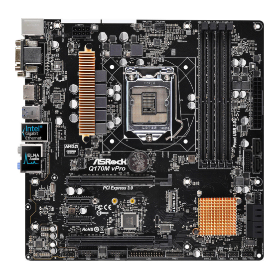
  • Seite 28 1 Einleitung Vielen Dank, dass Sie sich für das Q170M vPro von ASRock entschieden haben – ein zuverlässiges Motherboard, das konsequent unter der strengen Qualitätskontrolle von ASRock hergestellt wurde. Es liefert ausgezeichnete Leistung mit robustem Design, das ASRock Streben nach Qualität und Beständigkeit erfüllt.
  • Seite 29: Technische Daten

    Q170M vPro 1.2 Technische Daten • Micro-ATX-Formfaktor Plattform • Feststoffkondensator-Design • Leiterplatte mit hochdichtem Glasgewebe • Unterstützt die Prozessoren Intel® Core Prozessor i7/i5/i3/Pentium®/ Celeron® der 6. Generation (Sockel 1151) • Digipower-Design • 6-Leistungsphasendesign • Unterstützt Intel® Turbo Boost 2.0-Technologie • Intel® Q170 Chipsatz • Unterstützt Intel®...
  • Seite 30 • Unterstützt Blu-ray- (BD) Wiedergabe (Full HD/1080p) mit DVI-D- und HDMI-Ports • 7.1-Kanal-HD-Audio mit Inhaltsschutz (Realtek Audio ALC892-Audiocodec) • Erstklassige Blu-ray-Audiounterstützung • Unterstützt Überspannungsschutz (ASRock Full Spike Protection) • ELNA-Audiokondensatoren • Gigabit LAN 10/100/1000 Mb/s • Giga PHY Intel® I219LM • Unterstützt Wake-On-LAN • Unterstützt Blitzschutz/Schutz gegen elektrostatische...
  • Seite 31 • 1 x 8-poliger 12-V-Netzanschluss • 1 x Audioanschluss an Frontblende • 1 x USB 2.0-Stiftleiste (unterstützt 2 USB 2.0-Ports) (unterstützt Schutz gegen elektrostatische Entladung (ASRock Full Spike Protection)) • 1 x USB 3.0-Stiftleiste (unterstützt 2 USB 3.0-Ports) (unterstützt Schutz gegen elektrostatische Entladung (ASRock Full Spike Protection)) • 128-Mb-AMI-UEFI-Legal-BIOS mit Unterstützung...
  • Seite 32 Zertifizierun- • ErP/EuP ready (ErP/EuP ready-Netzteil erforderlich) * Detaillierte Produktinformationen finden Sie auf unserer Webseite: http://www.asrock.com Bitte beachten Sie, dass mit einer Übertaktung, zu der die Anpassung von BIOS-Einstellungen, die Anwendung der Untied Overclocking Technology oder die Nutzung von Übertaktung- swerkzeugen von Drittanbietern zählen, bestimmte Risiken verbunden sind.
  • Seite 33: Jumpereinstellung

    Q170M vPro 1.3 Jumpereinstellung Die Abbildung zeigt, wie die Jumper eingestellt werden. Wenn die Jumper-Kappe auf den Kontakten angebracht ist, ist der Jumper „kurzgeschlossen“. Wenn keine Jumper- Kappe auf den Kontakten angebracht ist, ist der Jumper „offen“. Die Abbildung zeigt einen 3-poligen Jumper, dessen Kontakt 1 und Kontakt 2 „kurzgeschlossen“...
  • Seite 34: Integrierte Stiftleisten Und Anschlüsse

    1.4 Integrierte Stiftleisten und Anschlüsse Integrierte Stiftleisten und Anschlüsse sind KEINE Jumper. Bringen Sie KEINE Jumper-Kappen an diesen Stiftleisten und Anschlüssen an. Durch Anbringen von Jumper-Kappen an diesen Stiftleisten und Anschlüssen können Sie das Motherboard dauerhaft beschädigen. Systemblende-Stiftleiste Verbinden Sie PLED+ PLED- PWRBTN#...
  • Seite 35 Q170M vPro Gehäuseeingriffs- und Bitte verbinden Sie Gehäu- SPEAKER DUMMY Lautsprecher-Stiftleiste seeingriffsvorrichtung und DUMMY (7-polig, SPK_CI1) den Gehäuselautsprecher (siehe S. 1, Nr. 15) mit dieser Stiftleiste. SIGNAL DUMMY Serial-ATA-III-Anschlüsse Diese sechs SATA-III- (SATA3_0: Anschlüsse unterstützen siehe S. 1, Nr. 6) SATA-Datenkabel für...
  • Seite 36 Audiostiftleiste Diese Stiftleiste dient PRESENCE# MIC_RET (Frontblende) dem Anschließen von OUT_RET (9-polig, HD_AUDIO1) Audiogeräten an der (siehe S. 1, Nr. 22) Frontblende. OUT2_L J_SENSE OUT2_R MIC2_R MIC2_L 1. High Definition Audio unterstützt Anschlusserkennung, der Draht am Gehäuse muss dazu jedoch HDA unterstützt. Bitte befolgen Sie zum Installieren Ihres Systems die Anweisungen in unserer Anleitung und der Anleitung zum Gehäuse.
  • Seite 37 Q170M vPro ATX-Netzanschluss Dieses Motherboard (24-polig, ATXPWR1) bietet einen 24-poligen (siehe S. 1, Nr. 5) ATX-Netzanschluss. Bitte schließen Sie es zur Nutzung eines 20-poligen ATX-Netzteils entlang Kontakt 1 und Kontakt 13 an. ATX-12-V-Netzanschluss Dieses Motherboard bietet (8-polig, ATX12V1) einen 8-poligen ATX- (siehe S.
  • Seite 38: Contenu De L'emballage

    Si vous avez besoin d’une assistance technique pour votre carte mère, veuillez visiter notre site Internet pour plus de détails sur le modèle que vous utilisez. La liste la plus récente des cartes VGA et des processeurs pris en charge est également disponible sur le site Internet de ASRock. Site Internet ASRock http://www.asrock.com.
  • Seite 39: Spécifications

    Q170M vPro 1.2 Spécifications • Facteur de forme Micro ATX Plateforme • Conception à condensateurs solides • PCB en tissu de verre haute densité • Prend en charge les processeurs 6 Processeur génération Intel® Core i7/i5/i3/Pentium®/Celeron® (Socket 1151) • Conception Digi Power • Alimentation à...
  • Seite 40 • 1 x port HDMI • 6 x ports USB 3.0 (Protection contre les décharges électrostatiques (Protection complète contre les pics ASRock)) • 1 x port RJ-45 LAN avec LED (LED ACT/LIEN et LED VITESSE) • Connecteurs jack audio HD : Haut-parleur latéral / haut- parleur arrière / central / basses / entrée ligne / haut-parleur...
  • Seite 41 • 1 x socket Ultra M.2, prend en charge les modules M.2 SATA3 6,0 Go/s et M.2 PCI Express jusqu'à Gen3 x4 (32 Go/s) * Prend en charge le kit ASRock U.2 • 1 x embase pour port d’impression Connecteur • 2 x embase pour port COM...
  • Seite 42 Certifications • ErP/EuP Ready (alimentation ErP/EuP ready requise) * pour des informations détaillées de nos produits, veuillez visiter notre site : http://www.asrock.com Il est important de signaler que l’ o vercloking présente certains risques, incluant des modifi- cations du BIOS, l’ a pplication d’une technologie d’ o verclocking déliée et l’utilisation d’ o utils d’...
  • Seite 43 Q170M vPro 1.3 Configuration des cavaliers (jumpers) L’illustration ci-dessous vous renseigne sur la configuration des cavaliers (jumpers). Lorsque le capuchon du cavalier est installé sur les broches, le cavalier est « court-circuité ». Si le capuchon du cavalier n’ e st pas installé sur les broches, le cavalier est « ouvert ».
  • Seite 44 1.4 Embases et connecteurs de la carte mère Les embases et connecteurs situés sur la carte NE SONT PAS des cavaliers. Ne placez JAMAIS de capuchons de cavaliers sur ces embases ou connecteurs. Placer un capuchon de cavalier sur ces embases ou connecteurs endommagera irrémédiablement votre carte mère. Embase du panneau Branchez le bouton de PLED+...
  • Seite 45 Q170M vPro Prise DEL d’alimentation et Veuillez brancher SPEAKER DUMMY emplacement sur châssis l'emplacement sur le DUMMY (SPK_CI1 à 7 broches) châssis et le haut-parleur (voir p.1, No. 15) du châssis sur ce connecteur. SIGNAL DUMMY Connecteurs Serial ATA3 Ces six connecteurs...
  • Seite 46 Embase audio du panneau Cette embase sert au PRESENCE# MIC_RET frontal branchement des appareils OUT_RET (HD_AUDIO1 à 9 broches) audio au panneau audio (voir p.1, No. 22) frontal. OUT2_L J_SENSE OUT2_R MIC2_R MIC2_L 1. L’ a udio haute définition prend en charge la technologie Jack Sensing (détection de la fiche), mais le panneau grillagé...
  • Seite 47 Q170M vPro Connecteur d’alimentation Cette carte mère est dotée d’un connecteur (ATXPWR1 à 24 broches) d’alimentation ATX à 24 (voir p.1, No. 5) broches. Pour utiliser une alimentation ATX à 20 broches, veuillez effectuer les branchements sur la Broche 1 et la Broche 13.
  • Seite 48: Contenuto Della Confezione

    Web di ASRock senza ulteriore preavviso. Per il supporto tecnico correlato a questa scheda madre, visitare il nostro sito Web per informazioni specifiche relative al modello attualmente in uso.
  • Seite 49 Q170M vPro 1.2 Specifiche • Fattore di forma Micro ATX Piattaforma • Design condensatore solido • PCB di fibra di vetro ad alta densità • Supporta processori 6 Generation Intel® Core i7/i5/i3/ Pentium®/Celeron® (Socket 1151) • Design Digi Power • Potenza a 6 fasi • Supporta la tecnologia Intel®...
  • Seite 50 • 1 x porta DVI-D • 1 x porta HDMI • 6 x Porte USB 3.0 (supporto protezione da scariche elettrostatiche (ESD) (protezione completa ASRock dai picchi di corrente)) • 1 x porta LAN RJ-45 con LED (ACT/LINK LED e SPEED LED) • Connettori audio HD: Altoparlante laterale/altoparlante...
  • Seite 51 • 1 x Collettore USB 2.0 (supporta 2 porte USB 2.0) (supporto protezione da scariche elettrostatiche (ESD) (protezione completa ASRock dai picchi di corrente)) • 1 x Collettore USB 3.0 (supporta 2 porte USB 3.0) (supporto protezione da scariche elettrostatiche (ESD) (protezione completa ASRock dai picchi di corrente)) • AMI UEFI Legal BIOS 128Mb con interfaccia di supporto...
  • Seite 52 * Per installare Windows® 7, è necessario un disco di installazione modificato con i driver xHCI integrati nel file ISO. Fare riferimen- to a pagina 141 per altre istruzioni dettagliate. * Per il driver aggiornato di Windows® 10, visitare il sito ASRock all’indirizzo: http://www.asrock.com • FCC, CE, WHQL Certificazioni • ErP/EuP Ready (è...
  • Seite 53 Q170M vPro 1.3 Impostazione jumper L'illustrazione mostra in che modo vengono impostati i jumper. Quando il cappuccio del jumper è posizionato sui pin, il jumper è "cortocircuitato". Se sui pin non è posizionato alcun cappuccio del jumper, il jumper è "aperto". L'illustrazione mostra un jumper a 3 pin i cui pin1 e pin2 sono "cortocircuitati"...
  • Seite 54 1.4 Header e connettori sulla scheda Gli header e i connettori sulla scheda NON sono jumper. NON posizionare cappucci del jumper su questi header e connettori. Il posizionamento di cappucci del jumper su header e connettori provocherà danni permanenti alla scheda madre. Header sul pannello del Collegare l'interruttore PLED+...
  • Seite 55 Q170M vPro Collegamento altoparlante Collegare l’intrusione SPEAKER DUMMY e intrusione telaio telaio e l’altoparlante a DUMMY (SPK_CI1 a 7 pin) questo collegamento. (vedere pag. 1, n. 15) SIGNAL DUMMY Connettori Serial ATA3 Questi sei connettori (SATA3_0: SATA3 supportano cavi vedere pag. 1, n. 6)
  • Seite 56 Header audio pannello Questo header serve a PRESENCE# MIC_RET anteriore collegare i dispositivi OUT_RET (AUDIO1_HD a 9 pin) audio al pannello audio (vedere pag. 1, n. 22) anteriore. OUT2_L J_SENSE OUT2_R MIC2_R MIC2_L 1. L'audio ad alta definizione supporta le funzioni Jack sensing, ma il filo del pannello sullo chassis deve supportare HDA per funzionare correttamente.
  • Seite 57 Q170M vPro Connettore di Questa scheda madre è alimentazione ATX dotata di un connettore di (ATXPWR1 a 24 pin) alimentazione ATX a 24 (vedere pag. 1, n. 5) pin. Per utilizzare un'alimentazione ATX a 20 pin, collegarla lungo il pin 1 e il pin 13.
  • Seite 58: Contenido Del Paquete

    Si esta documentación sufre alguna modificación, la versión actualizada estará disponible en el sitio web de ASRock sin previo aviso. Si necesita asistencia técnica relacionada con esta placa base, visite nuestro sitio web para obtener información específica sobre el modelo que esté...
  • Seite 59: Especificaciones

    Q170M vPro 1.2 Especificaciones • Factor de forma Micro ATX Plataforma • Diseño de condensador sólido • PCB de fibra de vidrio de alta densidad • Admite la familia de procesadores Intel® Core i7/i5/i3/ Pentium®/Celeron® (zócalo 1151) de la 6ª generación • Diseño Digi Power...
  • Seite 60 • 1 puerto DVI-D • 1 puerto HDMI • 6 puertos USB 3.0 (compatible con protección contra electricidad estática (protección ASRock Full Spike)) • 1 puerto LAN RJ-45 con LED (ACT/LINK LED y SPEED LED) • Conector de audio HD: Altavoz lateral / Altavoz trasero / Central / Graves / Entrada de línea / Altavoz frontal /...
  • Seite 61 • 1 Zócalo Ultra M.2, que admite el módulo SATA3 6,0 Gb/s M.2 y el módulo PCI Express M.2 hasta Gen3 x4 (32 Gb/s) * Admiteel Kit U.2 de ASRock • 1 Base de conexiones de puerto de impresión Conector • 2 Cabezal de puerto COM...
  • Seite 62 ISO. Consulte la página 141 para obtener información más detallada. * Para obtener el controlador actualizado para Windows® 10, visite el sitio Web desde ASRock para obtener detalles: http://www.asrock.com • FCC, CE, WHQL Certifica- • Compatible con ErP/EuP (requiere toma de alimentación...
  • Seite 63 Q170M vPro 1.3 Instalación de los puentes La instalación muestra cómo deben instalarse los puentes. Cuando la tapa de puente se coloca en los pines, el puente queda “Corto”. Si no coloca la tapa de puente en los pines, el puente queda “Abierto”. La ilustración muestra un puente de 3 pines cuyo pin 1 y pin 2 son “Cortos”...
  • Seite 64 1.4 Conectores y cabezales incorporados Los cabezales y conectores incorporados NO son puentes. NO coloque tapas de puente sobre estos cabezales y conectores. Si coloca tapas de puente sobre los cabezales y conectores dañará de forma permanente la placa base. Cabezal del panel del sistema Conecte el interruptor de PLED+...
  • Seite 65 Q170M vPro Cabezal de intrusión de Conecte la intrusión de SPEAKER DUMMY chasis y de altavoces chasis y el altavoz del DUMMY (SPK_CI1 de 7 contactos) chasis a este cabezal. (consulte la pág.1, N.º 15) SIGNAL DUMMY Conectores Serie ATA3...
  • Seite 66 Cabezal de audio del panel Este cabezal se utiliza para PRESENCE# MIC_RET frontal conectar dispositivos de OUT_RET (HD_AUDIO1 de 9 pines) audio al panel de audio (consulte la pág.1, N.º 22) frontal. OUT2_L J_SENSE OUT2_R MIC2_R MIC2_L 1. El Audio de Alta Definición (HDA, en inglés) es compatible con el método de sensor de conectores, sin embargo, el cable del panel del chasis deberá...
  • Seite 67 Q170M vPro Conector de alimentación Esta placa base contiene un conector de (ATXPWR1 de 24 pines) alimentación ATX de 24 (consulte la pág.1, N.º 5) pines. Para utilizar una toma de alimentación ATX de 20 pines, conéctela en los Pines del 1 al 13.
  • Seite 68: Комплект Поставки

    уведомления. При необходимости технической поддержки, связанной с материнской платой, посетите веб-сайт и найдите на нем информацию о модели используемой вами материнской платы. На веб-сайте ASRock также можно найти самый последний перечень поддерживаемых VGA-карт и ЦП. Веб-сайт ASRock http://www.asrock.com. 1.1 Комплект поставки...
  • Seite 69 Q170M vPro 1.2 Спецификация • Форм-фактор Micro ATX Платформа • Схема на основе твердотельных конденсаторов • Печатная плата высокой плотности на основе стеклоткани • Поддержка процессоров 6- го Процессор поколения Intel® Core i5/i3/Pentium®/Celeron® (Socket 1151) • Digi Power design • Система питания 6 • Поддержка...
  • Seite 70 • 7.1-канальный звук высокой четкости HD Audio с Аудио защитой данных (аудиокодек Realtek ALC892) • Поддержка Premium Blu-ray Audio • Защита от перенапряжения (ASRock Full Spike Protection) • Конденсаторы для аудиосистем ELNA • Gigabit LAN 10/100/1000 Мб/с • Giga PHY Intel® I219LM • Поддержка...
  • Seite 71 • 1 x Ultra M.2 Socket, поддержка модуля M.2 SATA3 со скоростью обмена данными 6,0 ГБ/с и модуля M.2 PCI Express до версии Gen3 x4 (32 ГБ/с) * Поддержка комплекта ASRock U.2 • 1 x колодка порта принтера Разъемы • 2 x колодка СОМ-порта...
  • Seite 72 измененный установочный диск с драйверами xHCI, упакованными в файл ISO. Более подробные инструкции представлены на стр. 141. * Подробные сведения об обновлении драйвера Windows® 10 представлены на веб-сайте ASRock: http://www.asrock.com • FCC, CE, WHQL Сертификация • Совместимость с ErP/EuP (необходим блок питания, соответствующий...
  • Seite 73 Q170M vPro 1.3 Установка перемычек Установка перемычек показана на рисунке. При установке колпачковой перемычки на контакты перемычка «замкнута». Если колпачковая перемычка на контакты не установлена, перемычка «разомкнута». На рисунке показана 3-контактная перемычка с замкнутыми контактами 1 и 2 при установке на них...
  • Seite 74 1.4 Колодки и разъемы, расположенные на материнской плате Расположенные на материнской плате колодки и разъемы перемычками НЕ являются. НЕ устанавливайте на эти колодки и разъемы колпачковые перемычки. Установка колпачковых перемычек на эти колодки и разъемы может вызвать неустранимое повреждение материнской платы. Колодка...
  • Seite 75 Q170M vPro Колодка с разъемами Предназначена для SPEAKER DUMMY датчика вскрытия подключения датчика DUMMY корпуса и динамика вскрытия корпуса и (7-контактный SPK_CI1) корпусного динамика. (См. стр. 1, № 15) SIGNAL DUMMY Разъемы Serial ATA3 Эти шесть разъемов (SATA3_0: SATA3 предназначены...
  • Seite 76 Аудиоколодка передней Эта колодка PRESENCE# MIC_RET панели предназначена OUT_RET (9-контактная, для подключения HD_AUDIO1) аудиоустройств к OUT2_L (См. стр. 1, № 22) передней аудиопанели. J_SENSE OUT2_R MIC2_R MIC2_L 1. Аудиосистема высокого разрешения поддерживает функцию распознавания разъема, но для е правильной работы необходимо, чтобы провод панели корпуса поддерживал передачу...
  • Seite 77 Q170M vPro Разъем питания АТХ Эта материнская плата (24-контактный, снабжена 24-контактным ATXPWR1) разъемом питания АТХ. (См. стр. 1, № 5) Чтобы использовать 20-контактный разъем питания ATX, подключите его вдоль контакта 1 и контакта 13. Разъем питания АТХ 12 В Эта материнская плата...
  • Seite 78: Conteúdo Da Embalagem

    Se precisar de assistência técnica relacionada a esta placa principal, visite o nosso site para obter informações específicas sobre o modelo que estiver utilizando. Você também poderá encontrar a lista de placas VGA e CPU mais recentes suportadas no site da ASRock. Site da ASRock http://www.asrock.com.
  • Seite 79 Q170M vPro 1.2 Especificações • Micro ATX Form Factor Plataforma • Design de condensador sólido • Tecido de Vidro de Alta densidade PCB • Supports Processadores Intel® 6 ª Geração Core i7/i5/i3/ Pentium®/Celeron® (Soquete 1151) • Design Digi Power • Design com 6 fases de alimentação • Suporta a tecnologia Intel®...
  • Seite 80 • LAN Gigabit a 10/100/1000 Mb/s • Giga PHY Intel® I219LM • Suporta Wake-On-LAN • Suporta Proteção contra Relâmpago/ESD (Proteção Total Contra Picos ASRock) • Suporta Energy Efficient Ethernet 802.3az • Suporta PXE • 1 x Porta PS/2 para mouse/teclado E/S do • 1 x Porta D-Sub...
  • Seite 81 • 1 conector de áudio do painel frontal • 1 x Plataforma USB 2.0 (Suporta 2 portas USB 2.0) (Suporta Proteção ESD (Proteção Total Contra Picos ASRock)) • 1 x Plataforma USB 3.0 (Suporta 2 portas USB 3.0) (Suporta Proteção ESD (Proteção Total Contra Picos ASRock)) • 128Mb IAM Legal UEFI BIOS com suporte multilingue GUI...
  • Seite 82 ErP/EuP) * Para obter informações detalhadas sobre o produto, por favor, visite o nosso site: http://www.asrock.com Por favor, observe que existe um certo risco envolvendo overclocking, incluindo o ajuste das definições na BIOS, a aplicação de tecnologia Untied Overclocking ou a utilização de ferramentas de overclocking de terceiros.
  • Seite 83 Q170M vPro 1.3 Configuração dos jumpers A imagem abaixo mostra como os jumpers são configurados. Quando a tampa do jumper é colocada nos pinos, o jumper é "Curto". Se não for colocada uma tampa de jumper nos pinos, o jumper é "Aberto". A imagem mostra um jumper de 3 pinos cujos pino1 e pino2 estão "Curtos"...
  • Seite 84 1.4 Suportes e conectores onboard Os conectores e suportes onboard NÃO são jumpers. NÃO coloque tampas de jumpers sobre es- tes terminais e conectores Colocar tampas de jumpers sobre os terminais e conectores irá causar danos permanentes à placa-mãe. Suporte do painel de Ligue o botão de PLED+ PLED-...
  • Seite 85 Q170M vPro Intrusão do Chassi e Conecte a instrusão do SPEAKER DUMMY Cabeçote de Autofalante chassi e autofalante do DUMMY (SPK_CI1 de 7 pinos) chassi a este cabeçote. (ver p.1, N.º 15) SIGNAL DUMMY Conectores série ATA3 Estes seis conectores...
  • Seite 86 Suporte de áudio do painel Este suporte destina-se à PRESENCE# MIC_RET frontal conexão dos dispositivos OUT_RET (HD_AUDIO1 de 9 pinos) de áudio no painel de (ver p.1, N.º 22) áudio frontal. OUT2_L J_SENSE OUT2_R MIC2_R MIC2_L 1. O Áudio de alta definição suporta Sensor de Adaptador, mas o fio do painel no chassi deverá suportar HDA para funcionar corretamente.
  • Seite 87 Q170M vPro Conector de alimentação Esta placa-mãe inclui um conector de alimentação (ATXPWR1 de 24 pinos) ATX de 24 pinos. Para (ver p.1, N.º 5) utilizar uma fonte de alimentação ATX de 20 pinos, introduza-a no Pino 1 e Pino 13.
  • Seite 88: Ambalaj İçeriği

    Rock'ın web sitesinde yer alacaktır.. Bu anakart ile ilgili olarak teknik destek almak istiyorsanız, lütfen kullandığınız model hakkında özel bilgiler için web sitemizi ziyaret edin. En güncel VGA kartları ve CPU destek listelerini de ASRock'ın web sitesinden bulabilirsiniz. ASRock web sitesi http://www.asrock.com.
  • Seite 89 Q170M vPro 1.2 Özellikler • Micro ATX Form Faktörü Platform • Yekpare Kapasitör tasarımı • Yüksek Yoğunluklu Cam Elyaf PCB • 6. Nesil Intel® Core i7/i5/i3/Pentium®/Celeron® İşlemcileri destekler (Yuva 1151) • Dijital Güç tasarımı • 6 Güç Safhası tasarımı • Intel® Turbo Boost 2.0 Teknolojisini destekler • Intel®...
  • Seite 90 Blu-ray (BD) kayıttan yürütme destekler • İçerik Koruma Özelliği ile 7.1 CH HD Ses (Realtek ALC892 Ses Codec Bileşeni) • Üstün Blu-ray Ses desteği • Dalgalanma Koruması Destekler (ASRock Tam Ani Gerilim Koruması) • ELNA Ses Kapakları • Gigabit LAN 10/100/1000 Mb/s • Giga PHY Intel®...
  • Seite 91 • 1 x 8 pim 12V Güç Bağlayıcısı • 1 x Ön Panel Ses Bağlayıcısı • 1 x USB 2.0 Bağlantısı (2 USB 2.0 bağlantı noktası destekler) (ESD Koruması Destekler (ASRock Tam Ani Gerilim Koruması)) • 1 x USB 3.0 Bağlantısı (2 USB 3.0 bağlantı noktası destekler) (ESD Koruması...
  • Seite 92 • ErP/EuP için hazır (ErP/EuP için hazır güç beslemesi gereklidir) * Detaylı ürün bilgisi için, lütfen web sitemizi ziyaret edin: http://www.asrock.com Lütfen, BIOS ayarlarını düzenleme, Bağımsız Hız Aşırtma Teknolojinin uygulanması ya da üçüncü kişilerin hız aşırtma araçlarının kullanılması da dahil olmak üzere tüm hız aşırtma işlemlerinin belirli bir risk taşıdığını...
  • Seite 93 Q170M vPro 1.3 Bağlantı Teli Kurulumu Çizim, bağlantı tellerinin kurulumunu göstermektedir. Tel kapağı, pimlerin üzerine yerleştirildiğinde, tel "Kısa" olur. Pimlerin üzerinde tel kapağı bulunmadığında, tel "Açık" olur. Çizim, pin1 ve pin2 alanları "Kısa" olan ve bu iki pim üzerinde bir bağlantı...
  • Seite 94 1.4 Ekli Bağlantılar ve Bağlayıcılar Ekli bağlantılar ve bağlayıcılar bağlantı teli değildir. Bağlantı teli kapaklarını bu bağlantı ve bağlayıcılar üzerine yerleştirmeyin. Bağlantı teli kapaklarının bağlantılar ile bağlayıcılar üzerine yerleştirilmesi, anakarta kalıcı hasar verebilir. Sistem Paneli Bağlantısı Güç anahtarını bağlayın, PLED+ PLED- PWRBTN# (9-pin PANEL1)
  • Seite 95 Q170M vPro Kasa Yetkisiz Erişim ve Lütfen kasa yetkisiz erişim SPEAKER DUMMY Hoparlör Bağlantısı ve kasa hoparlörünü bu DUMMY (7 pimli SPK_CI1) bağlantıya takın. (bkz. sf.1, No. 15) SIGNAL DUMMY Seri ATA3 Bağlayıcıları Bu altı SATA3 bağlayıcısı, (SATA3_0: veri aktarım hızı 6,0 Gb/ bkz.
  • Seite 96 Ön Panel Ses Bağlantısı Bu bağlantı, ses aygıtlarının PRESENCE# MIC_RET (9-pin HD_AUDIO1) ön ses paneline bağlanması OUT_RET (bkz. sf.1, No. 22) içindir. OUT2_L J_SENSE OUT2_R MIC2_R MIC2_L 1. Yüksek Tanımlı Ses, Jak Algılama özelliğini destekler, ancak bu işlevin düzgün çalışabilmesi için kasa üzerindeki panel kablosunun HDA işlevini desteklemesi gerekmektedir.
  • Seite 97 Q170M vPro ATX Güç Bağlayıcısı Bu anakart, 24-pin ATX (24-pin ATXPWR1) güç bağlayıcısı sağlam- (bkz. sf.1, No. 5) aktadır. 20-pin ATX güç beslemesi kullanmak için, lütfen Pin 1 ve Pin 13'e bağlayın. ATX 12V Güç Bağlayıcısı Bu anakart, 8-pin ATX (8-pin ATX12V1) 12V güç...
  • Seite 98 제공합니다 . 마더보드 규격과 BIOS 소프트웨어를 업데이트할 수도 있기 때문에 , 이 문서의 내용은 예고 없이 변경될 수 있습니다 . 이 설명서가 변경될 경우 , 업데이트된 버전은 ASRock 의 웹사이트에서 추가 통지 없이 제공됩니다 . 이 마더보드와 관련하여 기술적 지원이...
  • Seite 99 Q170M vPro 1.2 규격 • Micro ATX 폼 팩터 플랫폼 • 솔리드 콘덴서 구조 • 고밀도 유리 직물 PCB • 6 세대 Intel® Core i7/i5/i3/Pentium®/Celeron® 프로세서 ( 소 켓 1151) 지원 • Digi 전원 구조 • 6 개 전원 위상 구조...
  • Seite 100 • D-Sub 포트 1 개 • DVI-D 포트 1 개 • HDMI 포트 1 개 • USB 3.0 포트 6 개 (ESD 보호 지원 (ASRock 풀 스파이크 보호 )) • LED 장착 RJ-45 LAN 포트 1 개 (ACT/LINK LED 및...
  • Seite 101 SATA3_1 이 비활성화됩니다 . • 울트라 M.2 소켓 1 개 , M.2 SATA3 6.0 Gb/s 모듈 및 Gen3 M.2 PCI Express 모듈 4 개 (32 Gb/s) 지원 * ASRock U.2 키트 지원 • 인쇄 포트 헤더 1 개 커넥터 • COM 포트 헤더 2 개...
  • Seite 102 인증 • ErP/EuP 사용 가능 (ErP/EuP 사용 가능 전원공급장치 필요 ) * 자세한 제품 정보에 대해서는 당사 웹사이트를 참조하십시오 : http://www.asrock.com BIOS 설정을 조정하거나 Untied Overclocking Technology 를 적용하거나 타업체의 오 버클로킹 도구를 사용하는 것을 포함하는 오버클로킹에는 어느 정도의 위험이 따른...
  • Seite 103 Q170M vPro 1.3 점퍼 설정 그림은 점퍼를 어떻게 설정하는지 보여줍니다 . 점퍼 캡을 핀에 씌우면 점퍼가 “단락” 됩니다 . 점퍼 캡을 핀에 씌우지 않으면 점퍼가 “단선”됩니다 . 그림은 3 핀 점퍼를 보여주며 핀 1 과 핀 2 는 점퍼 캡을 씌울 때 “단락”됩니다 .
  • Seite 104 1.4 온보드 헤더 및 커넥터 온보드 헤더와 커넥터는 점퍼가 아닙니다 . 점퍼 캡을 온보드 헤더와 커넥터에 씌우지 마십시오 . 점퍼 캡을 온보드 헤더와 커넥터에 씌우면 마더보드가 영구적으로 손상됩 니다 . 시스템 패널 헤더 섀시의 전원 스위치 , PLED+ PLED- PWRBTN# (9 핀...
  • Seite 105 Q170M vPro 섀시 침입 및 스피커 헤더 섀시 침입 및 섀시 스 SPEAKER DUMMY (7 핀 SPK_CI1) 피커를 이 헤더에 연결 DUMMY (1 페이지 , 15 번 항목 참조 ) 하십시오 . SIGNAL DUMMY 시리얼 ATA3 커넥터 이들 6 개의 SATA3 커...
  • Seite 106 전면 패널 오디오 헤더 이 헤더는 오디오 장치 (9 핀 HD_AUDIO1) 를 전면 오디오 패널에 PRESENCE# MIC_RET OUT_RET (1 페이지 , 22 번 항목 참조 ) 연결하는 데 사용됩니 다 . OUT2_L J_SENSE OUT2_R MIC2_R MIC2_L 1. 고음질 오디오는 잭 감지를 지원하지만 올바르게 작동하려면 섀시의 패널 와이어가 HDA 를...
  • Seite 107 Q170M vPro ATX 전원 커넥터 이 마더보드에는 24 (24 핀 ATXPWR1) 핀 ATX 전원 커넥터 (1 페이지 , 5 번 항목 참조 ) 가 탑재되어 있습니 다 . 20 핀 ATX 전원공 급장치를 사용하려면 핀 1 과 핀 13 을 따라...
  • Seite 108 トでは、 最新の VGA カードおよび CPU サポート一覧もご覧になれます。 ASRock ウェブ サイ ト http://www.asrock.com. 1.1 パッケージの内容 • ASRock Q170M vPro マザーボード (マイクロ ATX フォームファクター) • ASRock Q170M vPro クイックインストールガイ ド • ASRock Q170M vPro サポート CD • 2 x シリアル ATA (SATA) データケーブル (オプション)...
  • Seite 109 Q170M vPro 1.2 仕様 • マイクロ ATX フォームファクター プラット • 固体コンデンサ設計 フォーム • 高密度ガラス繊維 PCB • 第 6 世代 Intel® Core i7/i5/i3/Pentium®/Celeron® プロセッ サーに対応 (ソケッ ト 1151) • デジタル電源設計 • 6 電源フェーズ設計 • Intel® ターボブースト 2.0 テク ノロジーをサポート • Intel® Q170 チップセット...
  • Seite 110 • 1 x D-Sub ポート • 1 x DVI-D ポート • 1 x HDMI ポート • 6 x USB 3.0 ポート (静電気放電 (ESD) 保護に対応 (ASRock 完全スパイク保護) ) • LED 付き 1 x RJ-45 LAN ポート (ACT/LINK LED と SPEED LED)...
  • Seite 111 • 1 x 前面パネルオーディオコネクタ • 1 x USB 2.0 ヘッダー (2 個の USB 2.0 ポートに対応) ( 静電気 放電 (ESD) 保護に対応 (ASRock 完全スパイク保護) ) • 1 x USB 3.0 ヘッダー (2 個の USB 3.0 ポートに対応) ( 静電気 放電 (ESD) 保護に対応 (ASRock 完全スパイク保護) )...
  • Seite 112 • Microsoft® Windows® 10 64-bit / 8.1 64-bit / 7 32-bit / 7 64-bit * Windows® 7 OS をインストールするために、 xHCI ドライバが ISO ファイルに含まれる変更されたインストールディスクが必 要です。 詳しい説明については 141 ページを参照してく ださい。 * 更新された Windows® 10 ドライバについては、 ASRock のウェ ブサイ トで詳細をご確認く ださい : http://www.asrock.com • FCC、 CE、 WHQL 認証...
  • Seite 113 Q170M vPro 1.3 ジャンパー設定 このイラストは、 ジャンパーの設定方法を示しています。 ジャンパーキャップがピ ンに被さっていると、 ジャンパーは 「ショート」 です。 ジャンパーキャップがピンに被 さっていない場合には、 ジャンパーは 「オープン」 です。 この図は 3 ピンのジャンパー を表し、 ジャンパーキャップがピン 1 とピン 2 に被さっているとき、 これらのピンは 「ショート」 です。 CMOS クリアジャンパー (CLRMOS1) デフォルト CMOS のク リア (p.1、 No. 16 参照) CLRMOS1 を使って CMOS 内のデータをクリアできます。 ク リアして、 デフォルト...
  • Seite 114 1.4 オンボードのヘッダーとコネクター オンボードヘッダーとコネクターはジャンパーではありません。 これらヘッダーとコネク ターにはジャンパーキャップを被せないでく ださい。 ヘッダーおよびコネクターにジャン パーキャップを被せると、 マザーボードに永久損傷が起こるこ とがあります。 システムパネルヘッダー 電源スイッチを接続し、 PLED+ PLED- (9 ピンパネル 1) スイッチをリセッ トし、 下 PWRBTN# (p.1、 No. 14 参照) 記のピン割り当てに従っ て、 シャーシのシステムス RESET# テータス表示ランプをこ HDLED- のヘッダーにセッ トしま HDLED+ す。 ケーブルを接続すると きには、 ピンの+と−に 気をつけてく ださい。 PWRBTN (電源スイッチ)...
  • Seite 115 Q170M vPro シャーシイントルージョン シャーシイントルージョン SPEAKER とスピーカーヘッダー DUMMY とシャーシスピーカーを DUMMY (7 ピン SPK_CI1) このヘッダーに接続して (p.1、 No. 15 参照) く ださい。 SIGNAL DUMMY シリアル ATA3 コネクタ これら 6 つの SATA3 コネ ー クターは、 最高 6.0 Gb/ 秒 のデータ転送速度で内部 (SATA3_0: p.1、 No. 6 参照)...
  • Seite 116 フロントパネルオーディ このヘッダーは、 フロント PRESENCE# オヘッダー MIC_RET オーディオパネルにオー OUT_RET (9 ピン HD_AUDIO1) ディオデバイスを接続す (p.1、 No. 22 参照) るためのものです。 OUT2_L J_SENSE OUT2_R MIC2_R MIC2_L 1. ハイディフィニションオーディオはジャックセンシングをサポートしていますが、 正しく 機能するためには、 シャーシのパネルワイヤーが HDA をサポートしているこ とが必要 です。 お使いのシステムを取り付けるには、 当社のマニュアルおよびシャーシのマニュ アルの指示に従ってく ださい。 2. AC 97 オーディオパネルを使用する場合には、 次のステップで、 前面パネルオーディオ ヘッダーに取り付けてく...
  • Seite 117 Q170M vPro ATX 電源コネクタ このマザーボードは 24 ピ (24 ピン ATXPWR1) ン ATX 電源コネクタを提 (p.1、 No. 5 参照) 供します。 20 ピンの ATX 電源を使用するには、 ピ ン 1 と 13 番に合わせて 接続してく ださい。 ATX 12V 電源コネクター このマザーボードは 8 ピ (8 ピン ATX12V1) ン ATX12V 電源コネク...
  • Seite 118 另行通知。如果本文档有任何修改,则更新的版本将发布在华擎网站上,我们不会另 外进行通知。如果您需要与此主板相关的技术支持,请访问我们的网站以具体了解所 用型号的信息。您也可以在华擎网站上找到最新 VGA 卡和 CPU 支持列表。华擎网站 http://www.asrock.com。 1.1 包装清单 • 华擎 Q170M vPro 主板(Micro ATX 规格尺寸) • 华擎 Q170M vPro 快速安装指南 • 华擎 Q170M vPro 支持光盘 • 2 x 串行 ATA (SATA) 数据线(选购) • 1 x I/O 面板 • 1 x 螺丝(供 M.2 插座使用)...
  • Seite 119 Q170M vPro 1.2 规格 • Micro ATX 规格尺寸 平台 • 稳固的电容器设计 • 高密度防潮纤维电路板 • 支持第 6 代 Intel® Core i7/i5/i3/Pentium®/Celeron® 处理器 (Socket 1151) • Digi Power(帝捷)设计 • 6 电源相设计 • 支持 Intel® Turbo Boost 2.0 技术 • Intel® Q170 芯片集...
  • Seite 120 • 3 个图形输出选项: D-Sub、DVI-D 和 HDMI • 支持三台显示器 • 支持 HDMI,最大分辨率可达 4K x 2K (4096x2304) @ 24Hz • 支持 DVI-D,60Hz 时最大分辨率达 1920x1200 • 支持 D-Sub,60Hz 时最大分辨率达 1920x1200 • 通过 HDMI 端口(需要兼容的 HDMI 显示器)支持 Auto Lip Sync、Deep Color (12bpc), xvYCC 和 HBR(高位速率音 频)...
  • Seite 121 Q170M vPro • 6 x SATA3 6.0 Gb/s 接口,支持 RAID(RAID 0、RAID 1、 存储 RAID 5、RAID 10、Intel Rapid Storage Technology 14 和 Intel Smart Response Technology)、NCQ、AHCI 和热插拔 如果 M2_1 被 SATA 型 M.2 设备占用,SATA3_0 和 SATA3_1 将被禁用。 • 1 x 超级 M.2 接口,支持 M.2 SATA3 6.0 Gb/s 模块和 M.2 PCI Express 模块(最高...
  • Seite 122 • Microsoft® Windows® 10 64-bit / 8.1 64-bit / 7 32-bit / 7 64-bit 操作系统 * 要安装 Windows® 7 OS,需要 xHCI 驱动程序已封装到 ISO 文件的经修改的安装盘。请参考第 141 页了解详情。 * 有关已更新的 Windows® 10 驱动程序,请访问华擎网站了解 详情 : http://www.asrock.com • FCC、CE、WHQL 认证 • ErP/EuP 支持(需要支持 ErP/EuP 的电源) * 有关详细产品信息,请访问我们的网站: http://www.asrock.com 须认识到超频会有一定风险,包括调整...
  • Seite 123 Q170M vPro 1.3 跳线设置 此图显示如何设置跳线。将跳线帽装到这些针脚上时,跳线 “短接”。如果这 些针脚上没有装跳线帽,跳线 “开路”。此图显示 3 针跳线,当跳线帽装在针 脚 1 和针脚 2 上,它们“短接”。 清除 CMOS 跳线 (CLRMOS1) 默认 清除 CMOS (见第 1 页,第 16 个) CLRMOS1 允许您清除 CMOS 中的数据。要清除和重置系统参数到默认设 置,请关闭计算机,从电源上拔下电源线插头。等候 15 秒后,使用跳线帽将 CLRMOS1 上的针脚 2 和针脚 3 短接 5 秒。但是,请勿在更新 BIOS 后立即清...
  • Seite 124 1.4 板载接脚和接口 板载接脚和接口不是跳线。不要将跳线帽装到这些接脚和接口上。将跳线帽装到这些 接脚和接口上将会对主板造成永久性损坏。 系统面板接脚 按照下面的针脚分配, PLED+ PLED- PWRBTN# (9 针 PANEL1) 将机箱上的电源开关、 (见第 1 页, 第 14 个) 重置开关和系统状态指 示灯连接到此接脚。在 RESET# 连接线缆前请记下正负 HDLED- 针脚。 HDLED+ PWRBTN(电源开关): 连接到机箱前面板上的电源开关。您可以配置使用电源开关关闭系统的方式。 RESET(重置开关): 连接到机箱前面板上的重置开关。如果计算机死机,无法执行正常重新启动,按重置 开关重新启动计算机。 PLED(系统电源 LED): 连接到机箱前面板上的电源状态指示灯。系统操作操作时,此 LED 亮起。系统处在 S1/S3 睡眠状态时,此 LED 闪烁。系统处在 S4 睡眠状态或关机 (S5) 时,此 LED 熄灭。 HDLED(硬盘活动...
  • Seite 125 Q170M vPro 机箱侵入和扬声器接脚 请将机箱侵入和机箱扬 SPEAKER DUMMY (7 针 SPK_CI1) 声器连接到到此接脚。 DUMMY (见第 1 页,第 15 个) SIGNAL DUMMY 串行 ATA3 接口 这六个 SATA3 接口支持 最高 6.0 Gb/s 数据传输 (SATA3_0: 见第 1 页, 第 6 个) 速率的内部存储设备的 SATA 数据线。 (SATA3_1: 见第 1 页, 第 7 个)...
  • Seite 126 前面板音频接脚 此接脚用于将音频设备 (9 针 HD_AUDIO1) 连接到前音频面板。 PRESENCE# MIC_RET OUT_RET (见第 1 页,第 22 个) OUT2_L J_SENSE OUT2_R MIC2_R MIC2_L 1. 高清音频支持插孔感测,但机箱上的面板连线必须支持 HDA 才能正常工作。请按 照我们的手册和机箱手册的说明安装系统。 2. 如果您使用 AC’97 音频面板,请按照以下步骤将它安装到前面板音频接脚: A. 将 Mic_IN (MIC) 连接到 MIC2_L。 B. 将 Audio_R (RIN) 连接到 OUT2_R,将 Audio_L (LIN) 连接到 OUT2_L。 C.
  • Seite 127 Q170M vPro ATX 电源接口 此主板提供 24 针 ATX (24 针 ATXPWR1) 电源接口。要使用 20 针 (见第 1 页,第 5 个) ATX 电源,请沿针脚 1 和针脚 13 插接它。 ATX 12V 电源接口 此主板提供 8 针 ATX (8 针 ATX12V1) 12V 电源接口。要使用 4 (见第 1 页,第 1 个)...
  • Seite 128 电子信息产品污染控制标示 依据中国发布的「电子信息产品污染控制管理办法」及 SJ/T 11364-2006「电子 信息产品污染控制标示要求」,电子信息产品应进行标示,藉以向消费者揭露 产品中含有的有毒有害物质或元素不致发生外泄或突变从而对环境造成污染或 对人身、财产造成严重损害的期限。依上述规定,您可于本产品之印刷电路板 上看见图一之标示。图一中之数字为产品之环保使用期限。由此可知此主板之 环保使用期限为 10 年。 图一 有毒有害物质或元素的名称及含量说明 若您欲了解此产品的有毒有害物质或元素的名称及含量说明,请参照以下表格 及说明。 有害物质或元素 部件名称 铅 (Pb) 镉 (Cd) 汞 (Hg) 六价铬 (Cr(VI)) 多溴联苯 (PBB) 多溴二苯醚 (PBDE) 印刷电路板 及电子组件 外部信号连 接头及线材 O: 表示该有毒有害物质在该部件所有均质材料中的含量均在 SJ/T 11363-2006 标准规定 的限量要求以下。 X: 表示该有毒有害物质至少在该部件的某一均质材料中的含量超出 SJ/T 11363-2006 标准 规定的限量要求,然该部件仍符合欧盟指令...
  • Seite 129 由於主機板規格及 BIOS 軟體可能會更新,所以本文件內容如有變更,恕不另行通知。 如本文件有任何修改,可至華擎網站逕行取得更新版本,不另外通知。若您需要與本 主機板相關的技術支援,請上我們的網站瞭解有關您使用機型的特定資訊。您也可以 在華擎網站找到最新的 VGA 卡及 CPU 支援清單。華擎網站 http://www.asrock.com。 1.1 包裝內容 • 華擎 Q170M vPro 主機板(Micro ATX 尺寸) • 華擎 Q170M vPro 快速安裝指南 • 華擎 Q170M vPro 支援光碟 • 2 x Serial ATA (SATA) 資料纜線(選用) • 1 x I/O 面板外罩...
  • Seite 130 1.2 規格 • Micro ATX 尺寸 平台 • 固態電容設計 • 高密度防潮纖維電路板 • 支援第 6 代 Intel® Core i7/i5/i3/Pentium®/Celeron® 處理器 (插座 1151) • 數位電源設計 (Digi Power) • 6 電源相位設計 • 支援 Intel® Turbo Boost 2.0 技術 • Intel® Q170 晶片組 • 支援 Intel® vPro 技術...
  • Seite 131 Q170M vPro • 三個圖形輸出選項: D-Sub、DVI-D 及 HDMI • 支援三台顯示器 • 支援最高可達 4K x 2K (4096x2304) @ 24Hz 解析度的 HDMI • 支援最高達 1920x1200 @ 60Hz 解析度的 DVI-D • 支援最高達 1920x1200 @ 60Hz 解析度的 D-Sub • 支援使用 HDMI 連接埠(需相容於 HDMI 監視器)的 Auto Lip Sync、Deep Color (12bpc)、xvYCC 及 HBR(高位...
  • Seite 132 • 6 x SATA3 6.0 Gb/s 接頭可支援 RAID(RAID 0、RAID 1、 儲存裝置 RAID 5、RAID 10、Intel 快速儲存技術 14 及 Intel 智慧反 應技術)、NCQ、AHCI 及熱插拔等 * 若 M2_1 為 SATA 類型的 M.2 裝置佔用,將會停用 SATA3_0 和 SATA3_1。 • 1 x Ultra M.2 插座,支援 M.2 SATA3 6.0 Gb/s 模組與 M.2 PCI Express 模組(最高可達...
  • Seite 133 Q170M vPro • Microsoft® Windows® 10 64 位元/ 8.1 64 位元/ 7 32 位元/ 作業系統 7 64 位元 * 若要安裝 Windows® 7 作業系統,需要使用修改過的安裝光 碟(已將 xHCI 驅動程式封裝至 ISO 檔案)。如需詳細說明, 請查看第 141 頁。 * 關於最新 Windows® 10 驅動程式的詳細資訊,請瀏覽華擎網 站:http://www.asrock.com • FCC、CE、WHQL 認證...
  • Seite 134 1.3 跳線設定 圖例顯示設定跳線的方式。當跳線帽套在針腳上時,該跳線為「短路」。若沒 有跳線帽套在針腳上,該跳線為「開啟」。圖例顯示當 3-pin 跳線的跳線蓋套 在 pin1 及 pin2 時,這兩個針腳皆為「短路」。 清除 CMOS 跳線 (CLRMOS1) 預設 清除 CMOS (請參閱第 1 頁,編號 16) 您可利用 CLRMOS1 清除 CMOS 中的資料。若要清除及重設系統參數為預設 設定,請先關閉電腦電源,再拔下電源供應器的電源線。在等待 15 秒後, 請使用跳線帽讓 CLRMOS1 上的 pin2 及 pin3 短路約 5 秒。不過,請不要在更 新 BIOS 後立即清除 CMOS。若您需在更新 BIOS 後立即清除 CMOS,則必須 先重新啟動系統,然後於進行清除...
  • Seite 135 Q170M vPro 1.4 板載排針及接頭 板載排針及接頭都不是跳線。請勿將跳線帽套在這些排針及接頭上。將跳線帽套在排 針及接頭上,將造成主機板永久性的受損。 系統面板排針 請依照以下的針腳排 PLED+ PLED- PWRBTN# 列將機殼上的電源開 (9-pin PANEL1) (請參閱第 1 頁, 編號 14) 關、重設開關及系統 狀態指示燈連接至此 RESET# 排針。在連接纜線之 HDLED- 前請注意正負針腳。 HDLED+ PWRBTN ( 電源開關 ): 連接至機殼前面板上的電源開關。您可設定使用電源開關關閉系統電源的方式。 RESET ( 重設開關 ): 連接至機殼前面板上的重設開關。若電腦凍結且無法執行正常重新啟動,按下重設開 關即可重新啟動電腦。 PLED ( 系統電源 LED):...
  • Seite 136 機殼防護排針 機殼防護排針連接 SPEAKER DUMMY 至此排針。 (7-pin SPK_CI1) DUMMY (請參閱第 1 頁,編號 15) SIGNAL DUMMY Serial ATA3 接頭 這六組 SATA3 接頭 皆支援內部儲存裝 (SATA3_0: 請參閱第 1 頁,編號 6) 置的 SATA 資料纜 線,最高可達 6.0 (SATA3_1: 請參閱第 1 頁,編號 7) Gb/s 資料傳輸率。 * 若 M2_1 為 SATA (SATA3_2: 請參閱第...
  • Seite 137 Q170M vPro 前面板音訊排針 本排針適用於連接 PRESENCE# MIC_RET 音訊裝置至前面板 (9-pin HD_AUDIO1) OUT_RET (請參閱第 1 頁,編號 22) 音訊。 OUT2_L J_SENSE OUT2_R MIC2_R MIC2_L 1. 高解析度音訊支援智慧型音效介面偵測 (Jack Sensing),但機殼上的面板線必須支援 HDA 才能正確運作。請依本手冊及機殼手冊說明安裝系統。 2. 若您使用 AC’97 音訊面板,請按照以下步驟安裝至前面板音訊排針: A. 將 Mic_IN (MIC) 連接至 MIC2_L。 B. 將 Audio_R (RIN) 連接至 OUT2_R 且將 Audio_L (LIN) 連接至 OUT2_L。...
  • Seite 138 ATX 電源接頭 本主機板配備一組 24-pin ATX 電源接 (24-pin ATXPWR1) (請參閱第 1 頁,編號 5) 頭。若要使用 20-pin ATX 電源供應 器,請插入 Pin 1 及 Pin 13。 ATX 12V 電源接頭 本主機板配備一組 8-pin ATX 12V 電 (8-pin ATX12V1) (請參閱第 1 頁,編號 1) 源接頭。若要使用 4-pin ATX 電源供應 器,請插入...
  • Seite 139 Q170M vPro 1.2 Spesifikasi • Bentuk dan Ukuran Micro ATX Platform • Desain Kapasitor Solid • PCB Serat Kaca dengan Kerapatan Tinggi • Mendukung Prosesor i7/i5/i3/Pentium®/Celeron® (Soket 1151) Intel® Core Generasi ke-6 • Desain Digi Power • Desain 6 Fase Daya • Mendukung Teknologi Intel®...
  • Seite 140 • 1 x Port D-Sub Belakang • 1 x Port DVI-D • 1 x Port HDMI • 6 x Port USB 3.0 (Mendukung Perlindungan ESD (ASRock Full Spike Protection)) • 1 x Port LAN RJ-45 dengan LED (ACT/LINK LED dan SPEED LED) • Soket Audio HD: Speaker Samping/Speaker Belakang/Tengah/...
  • Seite 141 • 1 x Konektor Audio Panel Depan • 1 x Header USB 2.0 (Mendukung 2 port USB 2.0) (Mendukung Perlindungan ESD (ASRock Full Spike Protection)) • 1 x Header USB 3.0 (Mendukung 2 port USB 3.0) (Mendukung Perlindungan ESD (ASRock Full Spike Protection)) • 128Mb AMI UEFI Legal BIOS dengan dukungan GUI...
  • Seite 142 Sertifikasi • Siap untuk ErP/EuP (memerlukan catu daya untuk ErP/EuP) * Untuk informasi tentang produk rinci, kunjungi situs web kami: http://www.asrock.com Perlu diketahui, overclocking memiliki risiko tertentu, termasuk menyesuaikan pengaturan pada BIOS, menerapkan Teknologi Untied Overclocking, atau menggunakan alat overclocking pihak ketiga.
  • Seite 143 Requirements • A Windows® 7 installation disk or USB drive • USB 3.0 drivers (included in the ASRock Support CD or website) • A Windows® PC • Win7 USB Patcher (included in the ASRock Support CD or website) Scenarios...
  • Seite 144 Select the “Win7 Folder” from Step1 by clicking the red circle as shown as the picture below. Step 4 Select the “USB Driver Folder” by clicking the red circle as shown as the picture below. If you are using ASRock’s Support CD for the USB 3.0 driver, please select your CD-ROM.
  • Seite 145 Q170M vPro Step 5 Select where to save the ISO file by pressing the red circle as shown as the picture below. Step 6 If you want to burn the patched image to a CD, please check “Burn Image” and select “Target Device to Burn”.
  • Seite 146: Contact Information

    Contact Information If you need to contact ASRock or want to know more about ASRock, you’re welcome to visit ASRock’s website at http://www.asrock.com; or you may contact your dealer for further information. For technical questions, please submit a support request form at http://www.asrock.com/support/tsd.asp...

Inhaltsverzeichnis