Esser IQ8Quad Betriebsanleitung
Quicklinks
Betriebsanleitung
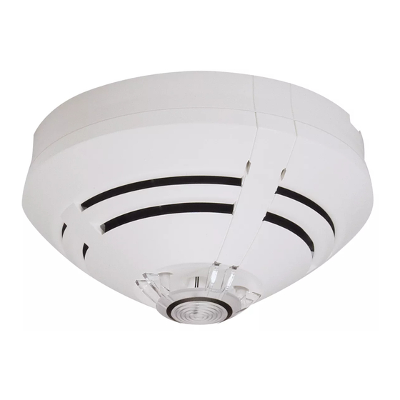
Brandmelder IQ8Quad
Operating Instruction
Fire Detector IQ8Quad
(Art.-Nr. / Part No. 802473)
Technische Änderungen vorbehalten!
GB
I
798930.40
Technical changes reserved!
D
02.2018 / AB
© 2018 Honeywell International Inc.
E
F
Novar GmbH a Honeywell Company
Dieselstraße 2, 41469 Neuss, Germany
Tel.: +49 2131 40615-600
Fax: +49 2131 40615-606
www.esser-systems.com
info@esser-systems.com
Achtung (D)
Brandmelder dienen dem Schutz von Personen und
Sachwerten und sollten nach der Installation auf die
einwandfreie Funktionalität überprüft werden.
Bei einer fehlerhaften Installation ist die ordnungsgemäße
Funktion nicht gewährleistet!
Bitte nationale Vorschriften / Richtlinien beachten!
Safety Notice (GB)
Fire detectors provide fire hazard protection for people and
property. After installing the detector it is thus crucial to check
carefully to ensure that the units are working properly.
Proper functioning cannot be guaranteed if the detectors are not
installed correctly in accordance with the instructions! Please
observe the relevant national regulations and guidelines!
Avvertenze (I)
I rilevatori d'incendio servono per proteggere le persone e le
cose dagli incendi. Pertanto, in seguito all'installazione del
sensore è fondamentale verificare che quest'ultimo funzioni
correttamente.
Se l'installazione dei rilevatori non viene eseguita correttamente
ed in conformità con le istruzioni, non è possibile garantire un
funzionamento corretto.
Attenersi alle norme e ai regolamenti in vigore nel paese di
utilizzo.
Atención (E)
Los avisadores de incendios sirven para la protección de
personas y valores materiales, debiendo ser comprobados,
después de la instalación, en cuanto a un funcionamiento
impecable.
¡En caso de una instalación incorrecta no está garantizado su
funcionamiento debido!
¡Sírvanse respetar las prescripciones / directivas nacionales!
Attention (F)
Les détecteurs d'incendie servent à assurer la protection des
personnes et des biens. Il est par conséquent nécessaire de vérifier
que leur fonctionnement est irréprochable après l'installation.
En cas d'une installation imparfaite, leur fonctionnement correct
n'est pas garanti !
Veuillez bien observer les prescriptions et les directives nationales!
D
Anwendung
Automatischer, punktförmiger Rauch bzw. Wärmemelder mit Gassensor
und integriertem Leitungstrenner zum Anschluss an den esserbus
oder esserbus
®
-PLus der ESSER-Brandmelderzentralen. Durch den
integrierten Gassensor eignet sich der Brandmelder besonders für die
Überwachung von Bereichen, in denen im Ereignisfall mit der Bildung
einer bestimmten Kohlenmonoxidkonzentration (CO) gerechnet werden
kann.
Besondere Kennzeichnung der IQ8Quad Brandmelder auf dem
Lichtleitteller:
Gasmelder
goldener Ring
Thermomelder
schwarzer Ring
Falschalarmquellen für Gasmelder
Gassensoren / -melder reagieren grundsätzlich auf mehrere Gasarten
(Querempfindlichkeit). Andere Gase, wie z.B. Wasserstoff (H
(C
H
) oder Stickstoffmonoxid (NO) können den Melder ab einer
2
2
bestimmten Konzentration bzw. zeitlich andauernder Beaufschlagung
stören oder auslösen. Daher ist im Überwachungsbereich des
Brandmelders auf das Vorhandensein anderer Gase zu achten. Diese
Gase können ggf. zu Störungen und/oder einer Änderung der
CO-Empfindlichkeit führen bzw. auch Falschalarme verursachen.
Falschalarmquellen für Rauchmelder
Aerosole mit sichtbaren Partikeln, wie z.B. durch Verbrennungsmaschinen,
Zigarettenrauch, Wasserdampf oder Staubablagerungen.
Falschalarmquellen für Thermomelder
Schneller, heftiger Anstieg der Umgebungstemperatur, Klima-/
Umluftanlagen.
Montage / Meldersockel
Die Brandmelder werden direkt in den zugehörigen Meldersockel
eingesetzt.
Standardsockel
Art.-Nr. 805590
Relaissockel
Art.-Nr. 805591
Option IP-Schutz
Art.-Nr. 805570, 805572.50 oder 805573
Inbetriebnahme
Die Inbetriebnahme der Brandmelder ist nur durch qualifiziertes und
im Umgang mit dem Brandmeldesystem eingewiesenes Fachpersonal
zulässig. Bei unzulässigen Arbeiten an dem Brandmelder erlöschen
die Garantie- und Gewährleistungsansprüche.
TAL-Funktion
Ein Technischer Alarm (TAL) bei Überschreitung einer CO-Konzentration
≥10 ppm ... ≤ 150 ppm ist über die Programmiersoftware tools 8000
programmierbar.
CO-Sensor
Die Betriebszeit des CO-Sensors beträgt gem. Herstellerangabe
> 5 Jahre. Die tatsächliche Betriebszeit wird durch die Umgebungs-
bedingungen am Montageort des Brandmelders beeinflusst, so dass
diese Zeit durchaus die Angabe übersteigen kann.
Spezielles Prüfverfahren
Die Besonderheit des OTG-Multisensormelders ist neben der
Verschmutzungskompensation ein spezielles Prüfverfahren, das eine
Störung des CO-Sensors rechtzeitig erkennt. Dieses Verfahren wird
mit der Programmiersoftware tools 8000 programmiert, ist während
des Prüfbetriebes der Brandmelderzentrale aktiv und die Anzeige
einer CO-Sensor-Störung erfolgt automatisch an der BMZ.
Dieses Verfahren kann dazu beitragen, dass die Betriebszeit des CO-
Sensors durchaus länger als 5 Jahre betragen kann.
Wartung
Alle Funktionen und der Zustand des Brandmelders werden zyklisch
melderintern geprüft und eine erforderliche Wartung automatisch
angefordert. Während des Prüfbetriebs des Systems werden die
Daten zur Zentrale übertragen und dort im Störungsfall angezeigt
(Anzeige
der
entsprechenden
Störungscodes
Zentralendisplay beachten).
Brandmelder ausschließlich mit der Programmier-
software tools 8000 in Betrieb nehmen, prüfen bzw.
warten!
Rauchmelder nur mit Rauchmeldertestgerät
(Art.-Nr. 805551 / 805582) und Prüfgas
(Art.-Nr. 805552 / 805584) testen!
Thermomelder nur mit Thermomeldertestgerät
(Art.-Nr. 805551 / 060429) testen!
Multisensormelder mit CO-Sensor mit Testgerät
(Art.-Nr. 805551 / 805582) und CO-Prüfgas
(Art.-Nr. 805553 / 805583) testen! Hierzu muss dass
Testgerät für ca. 3 Sekunden auslösen und für die Dauer
von ca. 7 Sekunden an den Melder gehalten werden, um
eine Abschwächung der CO-Konzentration zu vermeiden.
Ergänzende und aktuelle Informationen
Die Produktangaben entsprechen dem Stand der
Drucklegung und können durch Produktänderungen, ge-
änderte Normen/Richtlinien ggf. von den hier genannten
Informationen abweichen.
Aktualisierte Informationen zur Projektierung, Inbetrieb-
nahme und Wartung von Brandmeldern siehe unter
www.esser-systems.com!
esserbus
®
und essernet
®
in Deutschland ein eingetragene
Warenzeichen.
Technische Daten
Betriebsspannung
: 8 V DC ... 42 V DC
: 65 A
Ruhestrom @ 19 V DC
Ruhestrom @ BMZ
: 0,25 mA @ 27,5 V /
Akku
0,36 mA @ 42 V
Überwachungsfläche
: max. 110 m²
Überwachungshöhe
: max. 12 m
Alarmanzeige
: rote LED, blinkend
Luftgeschwindigkeit
: 0 ... 25,4 m/s
CO-Voralarm
: ca. 75 ppm
CO-Alarm
: ca. 100 ppm
Anwendungstemperatur
: -20 °C ... +50 °C
Lagertemperatur
: -25 °C ... +75 °C
: 95 % rel. Feuchte
Luftfeuchte
(ohne Betauung)
Schutzart
: IP 40 ... 43 (mit Sockel + Option)
Material
: ABS
Farbe
: weiß (ähnlich RAL 9010)
Gewicht
: ca. 110 g
Maße (mit Sockel)
: Ø 117 mm, H = 62 mm
Melderspezifikation
: EN 54-7 /-5 A2 /-17:2005, CEA 4021
VdS-Anerkennung
: G 205072
Leistungserklärung
: DoP-20115130701
Die Ermittlung der erforderlichen BMZ-Notstromkapazität
erfolgt über die Programmiersoftware tools 8000 bzw.
über die Berechnung unter www.esser-systems.com.
Application
Automatic point-type smoke or heat detector with Gas sensor and
integrated loop isolator to connect to the esserbus
®
PLus of the ESSER fire alarm control panels. Due to the integrated
gas sensor the detector is highly suitable for monitoring areas where
in case of an accident a definite appearance of carbon monoxide (CO)
must be assumed.
Special labelling of IQ8Quad Fire alarm detectors on the visual
indicator:
Gas detectors
golden ring
Heat detectors
black ring
False alarm sources for Gas detectors
Gas sensors or detectors basically respond to a several form of gas
), Acetylen
(cross sensitivity). Other gas types, e.g. Hydrogen (H
2
(C
H
) or Nitrogen monoxide (NO) may activate the detector if they
2
2
are present for a long time or with a specific concentration. Due to this
it is important to observe if other gas types are present in the
monitored area. Any additional gas in the monitored area may cause
a failure, alter the CO-sensitivity or may lead to false alarms.
False alarm sources for photoelectric Smoke detectors
Visible airborne particles or vapor, e.g. combustion engine exhausts,
cigarette smoke, steam or dust deposits.
False alarms for Heat detectors
Rapid, substantial increases in ambient temperature, air conditioning
and ventilation systems.
Installation / detector base
These detectors are mounted directly on the matching detector base.
Standard base
Relay base
Option IP rating
Configuration
Fire detectors are critical safety devices. They must be installed and
configured for use by qualified technicians familiar with the Fire Alarm
System. Any unauthorized work on or tampering with the detector will
void all warranty and guarantee claims.
TAL Function
A technical alarm (TAL) upon exceeding of a specific CO concentration
≥10 ppm ... ≤ 150 ppm can be programmed using the tools 8000
programming software.
CO Sensor
The operating life of the CO sensor is > 5 years, according to the
manufacturer. The actual operating life will be influenced by the
ambient conditions at the installation site of the fire detector, meaning
that even longer times may be achieved.
Special Testing Process
In addition to the soiling compensation, another special feature of the
OTG multisensor detector is a special testing process that promptly
detects faults in the CO sensor. This process is programmed with the
programming software tools 8000 and is active during operation of the
fire alarm control panel. Any CO sensor fault is automatically
displayed on the FACP.
This process can contribute to allowing the operating life of the CO
sensor to far exceed 5 years.
Maintenance
All detector functions and device status are checked at regular
intervals by the integrated diagnostics and provide an automatic
maintenance. The results are transferred to the control panel and any
errors are displayed there when the System is in test mode (Observe
auf
dem
corresponding fault codes in the panels display).
Commission, test and maintain fire detectors only with the
programming software tools 8000!
Use only smoke detector tester
(Part No. 805551 / 805582) and test gas
(Part No. 805552 / 805584) to test smoke detector
operation!
Use only test head for heat detector
(Part No. 805551 / 060429) to test heat detector operation!
Also test multisensor detector with CO sensor with smoke
detector tester (Part No. 805551 / 805582) and CO test gas
(Part No. 805553 / 805583). Therefore it is required to
activate the tester for 3s and hold it close to the detector
for at least 7s to avoid a dilution of the CO-concentration.
Additional and updated Informations
The product specification relate to the date of issue and
may differ due to modifications and/or amended
Standards and Regulations from the given informations.
For updated informations to commissioning and
maintenance of Fire alarm detectors refer to
www. esser-systems.com!
esserbus
®
and essernet
Germany.
Specifications
Operating voltage
Quiescent current @ 19 V DC : 65 A
Quiescent current @ FACP
Accu
Monitored area
Mounting height
Alarm indicator
Air velocity range
CO pre alarm
CO alarm
Ambient temperature
Temperature, storage
Ambient humidity
IP rating
Housing
Colour
Weight
Dimensions (with base)
Detector specification
VdS approval
Declaration of Performance
The FACP emergency power capacity is determined
using the programming software tools 8000 or via the
calculation function available at www.esser-systems.com.
GB
®
or esserbus
®
), Acetylene
2
Part No. 805590
Part No. 805591
Part No. 805570, 805572.50 or 805573
®
are registered trademarks in
: 8 V DC ... 42 V DC
: 0,25 mA @ 27,5 V /
0,36 mA @ 42 V
: max. 110 m²
: max. 12 m
: red LED, flashing
: 0 ... 25,4 m/s
: approx 75 ppm
: approx. 100 ppm
: -20 °C ... +50 °C
: -25 °C ... +75 °C
: 95% relative humidity
(non-condensing)
: IP 40 ... 43 (with base + option)
: ABS
: white (similar to RAL 9010)
: approx. 110 g
: Ø 117 mm, H = 62 mm
: EN 54-7 /-5 A2 /-17:2005, CEA 4021
: G 205072
: DoP-20115130701

Verwandte Anleitungen für Esser IQ8Quad


Inhaltszusammenfassung für Esser IQ8Quad
- Seite 1 ® ® und integriertem Leitungstrenner zum Anschluss an den esserbus PLus of the ESSER fire alarm control panels. Due to the integrated oder esserbus ® -PLus der ESSER-Brandmelderzentralen. Durch den gas sensor the detector is highly suitable for monitoring areas where integrierten Gassensor eignet sich der Brandmelder besonders für die...
- Seite 2 -PLus del centrales de detección de Signalisation ESSER. incendios de ESSER. Indicazioni speciali del rilevatore di incendio IQ8Quad sulla testa del Identificación especial de los detectores de incendios IQ8Quad en Étiquetage spécifique des détecteurs d’incendie IQ8Quad sur fotoconduttore: el indicador visual: l’indicateur visuel :...