Axis 25734 Handbuch

Verwandte Anleitungen für Axis 25734


Inhaltszusammenfassung für Axis 25734
- Seite 1 C O M M U N I C A T I O N S PRODUCT INSTRUCTIONS MODEL: 25734 Before attempting to connect or operate this product, 81-IN6222R3 please read these instructions completely.
-
Seite 2: Important Safeguards
TECHNICAL SUPPORT If technical support is needed, Axis has set-up a technical support In the event of a breach of the above warranty, Axis shall, line for their customers. at its option, repair or replace said product. This is Axis's sole obligation under this warranty. -
Seite 3: Electrical Specifications
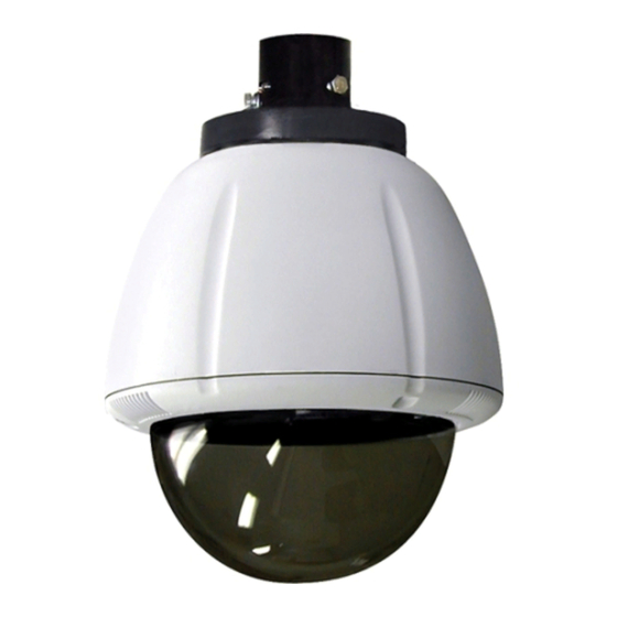
Content of Box Electrical Specifications 25734 Outdoor Housing (Clear) 35542 Outdoor Only (Tinted) Power 24VAC Class 2 Only Total Power: 89 Watts Heater: 50 Watts Blower: 2 Watts Camera Power: Up to 37 watts Input Connectors (Outdoor Units): English (1) BNC (Analog Video) - Seite 4 Wrap Teflon tape around the pipe threads Securely mount bracket to wall. Pull wiring to ensure a tight seal. through bracket and position grommet as shown. • Con seguridad soporte del montaje a emparedar. Tire del cableado • La cinta del Teflon del abrigo alrededor de la pipa rosca a través del soporte y del ojal de la posición según lo demostrado.
- Seite 5 Loop the lanyard over the set screw to Make the appropriate wiring connections temporarily hold housing. from the dome to the pendant. • Coloque el acollador sobre el tornillo de presión para • Hacer las conexiones de cableado de la cúpula de la celebrar temporalmente la cubierta.
- Seite 6 RJ45 24VAC SNC-RZ25/SNC-RZ550 Camera 18 Watts 25 Watts Camera Orange Heater/Blower Yellow 52 Watts Heater/Blower Green Alarm 1 Blue Alarm 2 Violet Alarm 3 Gray Common White RJ45 Make the appropriate male and female connections. Indoor model does not include pre-run cables. •...
- Seite 7 Axis 213 (3) #8x3/8” ½" Mounting Plate 1" Captive Screw 2" MOUNTING HOLE Install the camera to the mounting plate with (2) #10 screws and lock washers provided. Place (3) #8x3/8” screws on the spacers and align the mounting slots. Slide on plate and camera then secure.
- Seite 8 Axis 215 ½" 1" 1" Mounting Mounting Holes Holes 2" Attach camera to quick release plate as shown. Use spacers to assemble (4) 3” legs. Secure camera into position. • Una la cámara fotográfica a la placa rápida del lanzamiento según lo demostrado. Utilice los espaciadores para montar (4) las piernas del 3".
- Seite 9 Connection Module Screw Power Board This is what the typical path of illumination will look like with the setting at 30 degrees. To remove the power board, use screwdriver to release plastic fasteners by applying pressure to sides while pulling out. Attach connection module as shown.
- Seite 10 Axis 233D Remove 24Vac to 12VDC power board located inside of housing, attach 2 “L ” brackets to mounting plate. Connect Pan tilt with hardware provided. • Quite 24Vac al tablero de energía 12VDC situado dentro de la cubierta, una 2 "L" soportes a la placa de montaje.
- Seite 11 Align the arrows on the outside of the dome Connect Lanyard to trim ring assembly. and lock. • Alinee las flechas en el exterior de la bóveda y • Conecte el acollador con el montaje del anillo del trábese.
-
Seite 12: Replacement Parts List
Replacement Parts List 25734 Part Number Description RPFD7015 Lower Trim Ring RC7AT Tinted Replacement Capsule RC7AC Clear Replacement Capsule RPFD703 Dome Clamping Bracket RPFD072 24 Vac Heater RPFD080 (12 Vdc) Blower (Used In 24v Housings) RPFD060 Camera Bracket RPRH707 Connection Pcb...