Herunterladen Inhalt Inhalt Diese Seite drucken

Werbung

Verfügbare Sprachen

Verfügbare Sprachen

Manual
PL-REM-200
LINK
Driver
English....................Page 2
Nederlands.......Pagina 8
Français...............Page 14
Deutsch...............Seite 20

Werbung

Inhaltsverzeichnis
loading

Inhaltszusammenfassung für Duratech PL-REM-200

  • Seite 1 Manual English....Page 2 PL-REM-200 Nederlands..Pagina 8 Français....Page 14 Deutsch....Seite 20 LINK Driver...
  • Seite 2: Inhaltsverzeichnis

    Table of contents Technical specifications Page 3 Box contents Page 4 Installation instructions Page 5 Page 6 Pairing Handheld Transmitter & controller Handheld transmitter functions Page 7 Replacing transmitter battery Page 7 Troubleshooting Page 7...
  • Seite 3: Technical Specifications

    Technical specifications Electrical specifications Nominal Input voltage 230 VAC 50 Hz Output voltage on Lamp Output 12 VAC Max output current on Lamp Output 16,7 A Max rating Relay Contact A and B Resistive Load 14A 250VAC 14A 30VDC Inductive Load 6A 250VAC 6A 30VDC Transformer VA rating...
  • Seite 4: Box Contents

    Box contents 1. PL-REM-200 controller 2. Handheld transmitter (DuraLink™ version) 3. Spare battery (type A23 12V) 4. Screws (4x) & wall plugs (4x) 5. Owners’s manual...
  • Seite 5: Installation Instructions

    Installation instructions • Connect a 230VAC power source to the “220-240VAC INPUT” terminal • Connect the swimming pool lights to the “Lamp 12VAC output” terminal Make sure the total load of pool lights does not exceed 200Watt Optional: The “Switch A” & “switch B” terminals can be used to control auxiliary circuits like a pool cover or garden lights.
  • Seite 6: Pairing Handheld Transmitter & Controller

    2. Within 25 seconds, press any button on the handheld transmitter. --> If the transmitter is paired correctly, the LED will flash slowly for 5 times --> If the PL-REM-200 pairing memory is full, the LED will flash 15 times. This means 6 handheld devices have already been paired.
  • Seite 7: Handheld Transmitter Functions

    Handheld transmitter functions Toggle the lamps ON/OFF Go to next color scenario Toggle Output A ON/OFF Toggle Output B ON/OFF Replacing transmitter battery • Remove the philips head screw and open the transmitter • Replace the battery, respecting the polarity Battery type: A23 12V Troubleshooting PROBLEM...
  • Seite 8 Inhoudstafel Technische specificaties Pagina 9 Inhoud van de doos Pagina 10 Installatie-instructies Pagina 11 Pagina 12 Afstandsbediening en controller koppelen Afstandsbediening functies Pagina 13 Batterij van de afstandsbediening vervangen Pagina 13 Probleemoplossing Pagina 13...
  • Seite 9: Technische Specificaties

    Technische specificaties Elektrische specificaties Ingangsspanning (nominaal) 230 VAC 50 Hz Uitgangsspanning “Lamp 12VAC Output” 12 VAC Max stroom “Lamp 12VAC Output” 16,7 A Max vermogen Relais contact A en B Resistieve Belasting 14A 250VAC 14A 30VDC Inductieve Belasting 6A 250VAC 6A 30VDC Transformator vermogen 200VA...
  • Seite 10: Inhoud Van De Doos

    Inhoud van de doos 1. PL-REM-200 controller 2. Afstandsbediening (DuraLink™ versie) 3. Reserve batterij (type A23 12V) 4. Schroeven (4x) & muurpluggen (4x) 5. Handleiding...
  • Seite 11: Installatie-Instructies

    Installatie instructies • Verbind een 230VAC voedingsbron met de “220-240VAC INPUT” aansluitklem • Verbind de zwembadverlichting met de “Lamp 12VAC output” aansluitklem Zorg ervoor dat het totale vermogen van de zwembadverlichting niet hoger is dan 200Watt Optioneel: De “Switch A” & “switch B” aansluitklemmen kunnen gebruikt worden om additionele circuits (zoals tuin- verlichting of zwembadafdekking) aan te sturen Rode status LED...
  • Seite 12: Afstandsbediening En Controller Koppelen

    6 afstandsbedieningen. In probleemgevallen kan men de afstandsbe- diening ook manueel koppelen. Manueel koppel proces: Zorg ervoor dat de PL-REM-200 verbonden is met een 230VAC voeding. 1. Druk op de rode koppel-knop op het kleine printplaatje binnen in de controller, gedurende 5 seconden.
  • Seite 13: Afstandsbediening Functies

    Afstandsbediening functies Zet de lampen AAN/UIT Ga naar het volgende scenario Zet uitgang A AAN/UIT Zet uitgang B AAN/UIT Batterij van de afstandsbediening vervangen • Verwijder het kruiskop schroefje en open de afstandsbediening • Vervang de batterij en respecteer de polariteit Battery type: A23 12V Probleemoplossing PROBLEEM...
  • Seite 14 Table des matières Spécifications techniques Page 15 Contenu de la boîte Page 16 Instructions d’installation Page 17 Page 18 Appairage du contrôleur et de l’émetteur portatif Fonctions de l’émetteur portatif Page 19 Remplacer la batterie de l’émetteur Page 19 Résolution des problèmes Page 19...
  • Seite 15: Spécifications Techniques

    Spécifications techniques Spécifications électriques Tension d’entrée nominale 230 VAC - 50 Hz Tension de sortie à la sortie de la lampe 12 VAC Intensité électrique maximale à la sortie de la lampe 16,7 A Valeurs maximales des contacts de relais A et B Charge résistive 14 A 250 VAC 14 A 30 VDC...
  • Seite 16: Contenu De La Boîte

    Contenu de la boîte 1. Contrôleur PL-REM-200 2. Émetteur portatif (version DuraLink™) 3. Batterie de rechange (type A23 12V) 4. Vis (4x) & chevilles (4x) 5. Mode d’emploi...
  • Seite 17: Instructions D'installation

    Instructions d’installation • Raccordez une source d’alimentation de 230 VAC à la borne « 220-240 VAC INPUT » • Raccordez les lampes de la piscine à la borne « Lamp 12 VAC out- put » Assurez-vous que la charge totale des lampes de la piscine ne dépasse pas 200 Watts Optionnel : Les bornes «...
  • Seite 18: Appairage Du Contrôleur Et De L'émetteur Portatif

    Appairage du contrôleur et de l’émetteur portatif L’émetteur portatif est déjà appairé en usine et est donc prêt à l’emploi. Le PL-REM-200 peut être appairé avec un maximum de 6 émetteurs por- tatifs. Si un problème devait survenir, voici comment effectuer l’appairage...
  • Seite 19: Fonctions De L'émetteur Portatif

    Répétez processus d’ap- pairage. • Réduisez la distance entre l’émet- teur portatif et le PL-REM-200 et/ ou éliminez les obstacles. • Vérifiez le LED d’état rouge. Les lampes de la piscine ne • Vérifiez s’il y a bien une tension...
  • Seite 20 Inhaltsverzeichnis Technische Spezifikationen Seite 21 Lieferumfang Seite 22 Installationsanleitung Seite 23 Seite 24 Kopplung von Handsender und Regler Funktionen des Handsenders Seite 25 Handsenderbatterien auswechseln Seite 25 Störungsbehebung Seite 25...
  • Seite 21: Technische Spezifikationen

    Technische Spezifikationen Elektrische Spezifikationen Nominale Eingangsspannung 230 VAC 50 Hz Ausgangsspannung des Strahlerausgangs 12 VAC Max. Ausgangsstrom des Strahlerausgangs 16,7 A Max. Kapazität des Relaisausgangs A und B Ohmsche Last 14A 250VAC 14A 30VDC Induktive Last 6A 250VAC 6A 30VDC VA-Leistung Transformator 200VA Sicherungstyp...
  • Seite 22: Lieferumfang

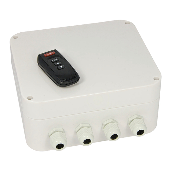
    Lieferumfang 1. PL-REM-200-Regler 2. Handsender (DuraLink™-Version) 3. Ersatzbatterie (Typ A23 12V) 4. Schrauben (4x) & Wanddübel (4x) 5. Betriebsanleitung...
  • Seite 23: Installationsanleitung

    Installationsanleitung • Schließen Sie eine 230VAC-Stromquelle an den “220-240VAC IN- PUT”-Anschluss • Verbinden Sie die Poolstrahler mit dem “Lamp 12VAC Output”-An- schluss Stellen Sie sicher, dass die Gesamtleistung aller Poolstrahler 200 Watt nicht überschreitet. Optional: Die “Switch A” & “Switch B”-Anschlüsse können zur Steuerung zusätzlicher Schaltkreise wie Pool abdeckung oder Gartenbeleuchtung verwendet werden.
  • Seite 24: Kopplung Von Handsender Und Regler

    Sollten Probleme auftreten, kann die Kopplung manuell durch- geführt werden: Manuelle Kopplung: Stellen Sie sicher, dass die PL-REM-200 an eine Stromquelle angeschlossen ist. Halten Sie den Kopplungsknopf auf der kleinen Schaltplatte im Regler für mindestens 5 Sekunden gedrückt.
  • Seite 25: Funktionen Des Handsenders

    • Der Handsender ist nicht korrekt mit dem Regler gekoppelt. • Kopplungsvorgang wiederholen • Entfernung zwischen Handsender und PL-REM-200 verringern bzw. Störquellen beseitigen • Rote Status-LED überprüfen Die Poolbeleuchtung funktioniert • Kontrollieren Sie, ob an den An- nicht schlüssen des Reglers eine Span- nung von 12VAC besteht •...
  • Seite 26 Notes...
  • Seite 28: Contact Details

    Contact details Propulsion Systems bvba Dooren 72 1785 Merchtem, Belgium Tel +32 2 461 02 53 Fax +32 2 706 59 60 www.propulsionsystems.be info@propulsionsystems.be We reserve the rights to change all or part of the contents of this document without prior notice...

Inhaltsverzeichnis