Kapitel
Inhaltsverzeichnis

Verwandte Anleitungen für urmet 1093/139M2


Inhaltszusammenfassung für urmet 1093/139M2
- Seite 1 Mod. 1093 DS1093-176 IP CAMERA 1080P SERIES BULLET 1093/139M2 1093/141M2 1093/142M2 MINIDOME VANDALDOME 1093/176M2 1093/177M2 1093/178M2 MANUALE D’USO USER MANUAL BEDIENUNGSANLEITUNG MANUEL D’UTILISATION MANUAL DE USUARIO...
-
Seite 2: Inhaltsverzeichnis
Apertura della confezione ....................... 3 Avvertenze ..........................4 INSTALLAZIONE ............................6 1093/139M2 Schema Telecamera IP Bullet ottica fissa ............. 6 1093/141M2 Schema Telecamera IP Bullet Varifocal ............7 1093/142M2 Schema Telecamera IP Bullet Varifocal ............8 ... -
Seite 3: Introduzione
Onde evitare eventuali conflitti di indirizzi IP, si consiglia di collegare e configurare in rete una telecamera IP alla volta. Il contenuto del manuale potrebbe essere diverso dalla vostra versione attuale. Se si riscontrano problemi durante le operazioni, contattare il reparto di supporto tecnico Urmet. Il manuale sarà aggiornato senza preavviso a intervalli irregolari. DESCRIZIONE DEL PRODOTTO I dispositivi URMET S.p.A. -
Seite 4: Avvertenze
Registrazioni immagini Questa apparecchiatura non è progettata come antifurto ma principalmente per trasmettere ed eventualmente per registrare immagini. Perciò, qualora l’utilizzatore subisca un furto, la società URMET S.p.A. non può essere considerata responsabile di alcuna perdita o danno conseguente. Effettuare una registrazione di prova prima di utilizzare l’apparecchiatura per verificare che l’operazione avvenga correttamente. - Seite 5 Per maggiori informazioni consultare l’indirizzo web http://www.garanteprivacy.it. Aggiornamento firmware Si consiglia di consultare periodicamente l’Area Tecnica Servizio Clienti di URMET SpA al fine di verificare la disponibilità di eventuali aggiornamenti firmware. Configurazione di rete La telecamera è...
-
Seite 6: Installazione
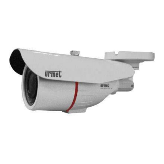
INSTALLAZIONE 1093/139M2 SCHEMA TELECAMERA IP BULLET OTTICA FISSA Parti Descrizione Visiera frontale Protegge la telecamera IP dai raggi del sole. ① Corpo camera Fissato alla visiera frontale tramite vite di fissaggio. ② Obiettivo Obiettivo della telecamera. ③ Illuminatore infrarossi Illuminatore a LED infrarossi. -
Seite 7: Schema Telecamera Ip Bullet Varifocal
1093/141M2 SCHEMA TELECAMERA IP BULLET VARIFOCAL Parti Descrizione Visiera frontale Protegge la telecamera IP dai raggi del sole. ① Corpo camera Fissato alla visiera frontale tramite vite di fissaggio. ② Obiettivo Obiettivo della telecamera. ③ Illuminatore infrarossi Illuminatore a LED infrarossi. ④... -
Seite 8: Schema Telecamera Ip Bullet Varifocal
1093/142M2 SCHEMA TELECAMERA IP BULLET VARIFOCAL Parti Descrizione Visiera frontale Protegge la telecamera IP dai raggi del sole. ① Corpo camera Fissato alla visiera frontale tramite vite di fissaggio. ② Obiettivo Obiettivo della telecamera. ③ Illuminatore infrarossi Illuminatore a LED infrarossi. ④... -
Seite 9: Schema Telecamera Ip Minidome
1093/176M2 SCHEMA TELECAMERA IP MINIDOME ① ③ ② ④ ⑥ ⑤ Parti Descrizione Obiettivo Obiettivo della telecamera. ① Illuminatore infrarossi Illuminatore a LED infrarossi. ② Cupola È girevole e può regolare l’angolo dell’inquadratura. ③ Ghiera di sicurezza e brugole di bloccaggio Fissa la posizione della cupola. -
Seite 10: Schema Telecamera Ip Minidome
1093/177M2 SCHEMA TELECAMERA IP MINIDOME ③ ① ④ ② ⑤ ⑥ Parti Descrizione Obiettivo Obiettivo della telecamera. ① Illuminatore infrarossi Illuminatore a LED infrarossi. ② Regolatori fuoco Regolano lunghezza fuoco e zoom. Si trovano all’interno svitando il corpo led ③ Cupola È... -
Seite 11: Schema Telecamera Ip Dome Anti Vandalo
1093/178M2 SCHEMA TELECAMERA IP DOME ANTI VANDALO ② ③ ① ④ ⑤ ⑥ Parti Descrizione Copertura trasparente Protegge la cupola. ① Illuminatore infrarossi Illuminatore a LED infrarossi. ② Obiettivo Obiettivo della telecamera. ③ Copertura interna nera Fissa la cupola. ④ Base con fori di fissaggio Fissa il dispositivo al punto scelto per l’installazione. -
Seite 12: Collegamento Del Dispositivo
COLLEGAMENTO DEL DISPOSITIVO Sono possibili due tipi di collegamento: Dispositivo connesso al PC Collegare la telecamera IP al PC con il cavo di rete. L’hub di alimentazione della telecamera IP è collegato all’alimentazione 12 Vcc. Impostare l’indirizzo IP del PC e quello della telecamera IP nello stesso segmento di rete. Se la rete è in condizioni normali, attendere per 1 minuto dopo l’accensione affinché... -
Seite 13: Campi Di Applicazione
CAMPI DI APPLICAZIONE La telecamera IP è solitamente utilizzata in grandi centri commerciali, supermercati, scuole, stabilimenti, laboratori e altri luoghi pubblici. Grazie alla sua elevata capacità di elaborazione delle immagini, la telecamera IP può essere utilizzata anche in ambienti che richiedano immagini ad alta definizione, quali banche e incroci stradali. Si veda la figura seguente. Centro di controllo EASYTOOL... -
Seite 14: Configurazione Dei Controlli Activex
Per prima cosa, selezionare il dispositivo del quale si deve modificare l’indirizzo IP e inserire inserire i nuovi valori di indirizzo IP, maschera di sottorete, gateway (maschera di sottorete e gateway possono essere ereditati dal PC) e nome utente/password. Cliccare su Modifica rete (Modify Network) per cambiare l’indirizzo IP del dispositivo. NOTA BENE L’indirizzo IP predefinito della telecamera IP è... -
Seite 15: Configurazione Della Pagina Web Della Telecamera Ip
CONFIGURAZIONE DELLA PAGINA WEB DELLA TELECAMERA IP LIVE Aprire Internet Explorer e inserire l’indirizzo IP della telecamera IP (http://192.168.1.168). Compare la finestra di dialogo di accesso. Si veda la figura seguente. L’utente può selezionare il Tipo di stream (Stream Type) nell’interfaccia di accesso. Inserire Nome utente (User name, predefinito: admin) e Password (predefinita: admin), selezionare la Lingua (Language) e cliccare su “Login”... -
Seite 16: Impostazioni Remote
: Snapshot, tipo di file, percorso di memorizzazione ecc.; : Uscita e ritorno all’interfaccia di accesso; : Mostra l’anteprima dei pulsanti di controllo. Da sinistra a destra, i nomi dei pulsanti sono Riproduzione, Stop, Schermo intero, Snapshot, Avvia/Arresta registrazione (Play, Stop, Full screen, Snapshot, Start/Stop recording). -
Seite 17: Controllo Dell'immagine
CONTROLLO DELL’IMMAGINE Cliccare su 【Display】→【Controllo immagine】(【Image Control】) per accedere all’interfaccia seguente. Modalità IRCUT (IRCUT Mode): 4 modalità: GPIO Auto, Video Auto, Modalità colore (Color Mode) e Modalità bianco/nero (Black & White Mode). Ritardo IR-CUT (IR-CUT Delay): Tempo di commutazione del ritardo IRcut Impostazione immagine (Image setting): Regolazione di luminosità, contrasto, saturazione, tinta e nitidezza. -
Seite 18: Rete
ZONA PRIVACY Cliccare su 【Display】→【Zona Privacy】(【Privacy Zone】) per accedere all’interfaccia seguente. Impostazione della zona privacy: 1. Cliccare per abilitare la zona privacy. 2. Tenendo premuto il pulsante sinistro, trascinare il mouse per selezionare la zona privacy (massimo 4 zone). 3. Cliccare su Salva (Save) per rendere attiva la zona privacy. Cancella (Clear): Cliccare su questo pulsante per eliminare tutte le zone privacy. - Seite 19 Porta HTTP (HTTP Port): Porta web della telecamera IP Indirizzo IP (IP address): Indirizzo IP della telecamera IP Maschera di sottorete (Subnet Mask): Maschera di sottorete della telecamera IP Gateway: Gateway predefinito del dispositivo DNS1/DNS2: Configurazione del server DNS Porta multimediale (Media Port): Porta client della telecamera IP Porta mobile (Mobile Port): Porta di connessione del client mobile Indirizzo MAC (MAC address): Indirizzo MAC della telecamera IP Streaming video...
- Seite 20 Email Cliccare su 【Rete】(【Network】) →【Email】 per accedere all’interfaccia seguente. Impostazione del servizio e-mail. Utilizzando questa funzione con la funzione di allarme, le immagini acquisite durante gli allarmi possono essere caricate sul server E-mail attraverso la rete. Porta SMTP (SMTP Port): Il valore predefinito è 25 (porta Email: Disabilita/Abilita (Disable/Enable) di servizio e-mail) Autenticazione (Authentication): Disabilita/Abilita...
- Seite 21 DDNS Cliccare su 【Rete】(【Network】) →【DDNS】 per accedere all’interfaccia seguente. : Si riferisce al Dynamic Domain Name Server, che è utilizzato insieme al server per l’accesso alle reti esterne. DDNS: Disabilita/Abilita (Disable/Enable) Server: Selezionare il provider DDNS Nome Host (Host Name): Inserire il nome Nome Utente (User Name): Nome dell’utente dell’host Tempo di aggiornamento (Update Time): tempo di...
- Seite 22 I parametri della TELECAMERA IP devono essere allocati manualmente. Selezionare “Tipo = Statico (Type = Static)” nel “Menu Rete (Network)” e compilare i campi seguenti: Indirizzo IP (IP address), Maschera di sottorete (Subnet mask), Gateway e DNS. Premere Salva (Save) per salvare le modifiche. NOTA BENE: Per la corretta funzionalità...
- Seite 23 RTSP Cliccare su 【Rete】(【Network】) →【RTSP】 per accedere all’interfaccia seguente. Porta RTSP (RTSP Port): Il valore predefinito è 554. Dopo la modifica, il dispositivo sarà riavviato. Descrizione • rtsp://IP:Port/live/A/B • IP: Indirizzo IP del dispositivo • Port: porta rtsp del dispositivo •...
-
Seite 24: Allarme
7.2.3 ALLARME MOVIMENTO Cliccare su 【Allarme】→【Movimento】(【Alarm】→【Motion】) per accedere all’interfaccia seguente. Procedura di impostazione 1. Abilitare/disabilitare il rilevamento del movimento. 2. Tenendo premuto il pulsante sinistro, trascinare il mouse per selezionare l’area di rilevamento del movimento (massimo 4 aree). 3. Impostare la sensibilità di rilevamento del movimento (opzioni: Alta, Media, Bassa (High, Medium, Low)). 4. -
Seite 25: Sistema
7.2.4 SISTEMA Il menu System contiene le voci 【Data/Ora】(Date/Time),【Utenti】(Users), 【Info】e【Registro】(Log). Le relative interfacce e descrizioni sono riportate di seguito. 1) IMPOSTAZIONE DI DATA/ORA Cliccare su【Sistema】(System) →【Data/Ora】(Date/Time) per accedere all’interfaccia seguente. PARAMETRI: qui è possibile modificare il Nome dispositivo (Device Name). DATA/ORA (DATE/TIME): in questa interfaccia l’utente può... - Seite 26 UTENTI Cliccare su 【Sistema】→【Utenti】(【System】→【Users】) per accedere all’interfaccia seguente. Qui è possibile creare, attivare e disattivare nuovi utenti e gestire le password. INFO Cliccare su 【Sistema】(【System】) →【Info】 per accedere all’interfaccia seguente. DS1093-176...
-
Seite 27: Avanzate
In essa sono riportate le informazioni di sistema del dispositivo, come modello, numero di serie, versione software ecc. Registro Cliccare su 【Sistema】→【Registro】(【System】→【Log】) per accedere all’interfaccia seguente. Tipo registro (Log Type): è possibile selezionare tra 5 tipi (registro di sistema, registro parametri, registro record, registro utenti, registro allarmi, registro eccezioni, registro memoria, registro globale). -
Seite 28: Impostazioni Locali
Caricamento dei parametri predefiniti Cliccare su 【Avanzate】→【Carica predefiniti 】( 【Advanced】→ 【Load Default】) per accedere all’interfaccia seguente. Nell’opzione “Carica predefiniti (Load Default)”, cliccare su “Reset ai valori di fabbrica (Reset factory settings)” e premere il pulsante Salva (Save) per ripristinare le impostazioni di fabbrica. Cliccare su “Riavvia (Reboot)”... -
Seite 29: Caratteristiche Tecniche Della Telecamera Ip Bullet
Frame rate Main e Sub stream 352*288 Mobilestream 704*576 640*360 352*288 Immagine Impostazione immagine Regolazione di saturazione, luminosità e contrasto tramite Urmet NVR, IE N. max. di PC connessi alla Utenti Telecamera IP Multi browser Software Web/Client/ Mobile Client UVS Urmet supportato solo tramite NVR... - Seite 30 352*288 Mobilestream 704*576 640*360 352*288 Immagine Impostazione immagine Regolazione di saturazione, luminosità e contrasto tramite Urmet NVR, IE N. max. di PC connessi alla Utenti Telecamera IP Multi browser Software Web/Client/ Mobile Client UVS Urmet supportato solo tramite NVR...
-
Seite 31: Appendice
APPENDICE PORT-FORWARDING DEL ROUTER Se desidera ispezionare l’immagine di monitoraggio della telecamera IP tramite Internet, l’utente deve aprire la porta web e la porta client della telecamera IP. Si consideri un router Cisco come esempio: L’indirizzo IP della telecamera IP è 192.168.1.168, il numero della porta web è 8000 e quello della porta cliente è 9988. F.A.Q. - Seite 32 Warnings ............................ 34 Installation ..............................36 1093/139M2 Schematic Diagram for Bullet IP Camera with fixed lens built-in ..... 36 1093/141M2 Schematic Diagram for Bullet Varifocal IP Camera ......... 37 1093/142M2 Schematic Diagram for Bullet Varifocal IP Camera .........
-
Seite 33: Introduction
Do not connect more then a IP Camera in the same sub-net, it could cause an IP Address conflict in the Network. The contents in the manual may be different from your current version. If you encounter any unsolved problem during operation, please contact Urmet technical support department. The manual will be updated irregularly without prior notice. -
Seite 34: Warnings
Disconnect the device from the electrical outlet before cleaning. Video recording This device is not designed as a burglar system but mainly to transmit and record video images. URMET S.p.A. is not in any way responsible for loss or damages of the user consequent to theft. - Seite 35 Camera default setting is DHCP mode. If the network does not support dynamic addressing (DHCP), the device will automatically switch to factory IP 192.168.1.168. Use Urmet ““EasyTool” software to modify the IP address and other network settings to prevent any conflict with other devices on the network.
-
Seite 36: Installation
INSTALLATION 1093/139M2 SCHEMATIC DIAGRAM FOR BULLET IP CAMERA WITH FIXED LENS BUILT-IN Items Descriptions Front cover It can prevent the IP camera from the irradiation of the sunlight. ① Camera body It is fixed to the front cover through the set screw. -
Seite 37: Schematic Diagram For Bullet Varifocal Ip Camera
1093/141M2 SCHEMATIC DIAGRAM FOR BULLET VARIFOCAL IP CAMERA Items Descriptions Front cover It can prevent the IP camera from the irradiation of the sunlight. ① Camera body It is fixed to the front cover through the set screw. ② Lens Lens of camera ③... -
Seite 38: Schematic Diagram For Bullet Varifocal Ip Camera
1093/142M2 SCHEMATIC DIAGRAM FOR BULLET VARIFOCAL IP CAMERA Items Descriptions Front cover It can prevent the IP camera from the irradiation of the sunlight. ① Camera body It is fixed to the front cover through the set screw. ② Lens Lens of camera. -
Seite 39: 1093/176M2 Schematic Diagram For Minidome Ip Camera
1093/176M2 SCHEMATIC DIAGRAM FOR MINIDOME IP CAMERA ① ③ ② ④ ⑥ ⑤ Items Descriptions Lens Lens of camera ① Infrared lamp Infrared LED lamp ② Hemisphere It is rotatable and used to adjust the installation angle ③ Security ring nut with blocking allens Fix the position of the hemisphere. -
Seite 40: 1093/177M2 Schematic Diagram For Minidome Ip Camera
1093/177M2 SCHEMATIC DIAGRAM FOR MINIDOME IP CAMERA ③ ① ④ ② ⑤ ⑥ Items Descriptions Lens Lens of camera ① Infrared lamp Infrared LED lamp ② Focusing level They adjust focus and zoom length. Located inside the camera unscrewing the ③... -
Seite 41: 1093/178M2 Schematic Diagram For Vandal Dome Ip Camera
1093/178M2 SCHEMATIC DIAGRAM FOR VANDAL DOME IP CAMERA ② ③ ① ④ ⑤ ⑥ Items Descriptions Transparent cover Protect the hemisphere ① Infrared lamp Infrared LED lamp ② Lens Lens of camera ③ Black inner cover Fix the hemisphere ④ Base with fixing holes. -
Seite 42: Device Connection
DEVICE CONNECTION There are two types of connection: Connect the device with PC Connect IP camera with PC by network cable. The supply hub of IP camera is connected with DC 12V power supply. Set the IP address of PC and that of IP camera in the same network segment. If the network is normal, wait for 1 minute after power on and IP camera will establish communictaion with PC. -
Seite 43: Application Fields
APPLICATION FIELDS IP camera is usually applied in large-scale shopping malls, supermarkets, schools, plants, workshops, and other public places. As it has strong image processing capacity, IP camera can also be used in the environment requiring high definition of image, such as bank and traffic intersection. Refer to the following picture. Monitoring Center “EASYTOOL... -
Seite 44: Activex Control Setup
If the searched IP address and PC IP address are not in the same network segment, user may modify IP address, subnet mask, and other parameters of IP camera by using Easy Tool software. First select the device to modify IP address and then input new IP address, subnet mask, gateway (subnet mask and gateway can be inherited by PC) and username/password. -
Seite 45: Webpage Configuration Of Ip Camera
WEBPAGE CONFIGURATION OF IP CAMERA LIVE Open Internet Explorer and input IP address of IP camera(http://192.168.1.168). The login dialog box will appear. See the following picture:. User may select Stream Type in the login interface. Input user name (default: admin) and password (default: admin), Language and click “Login” to enter the Live interface, as shown in the following picture. -
Seite 46: Remote Settings
Other buttons on the Live interface: :Enter the device setting menu and set customized parameters of the device; :Snapshot, file type, storage path, etc.; :Log out and return to the login interface; :It shows preview control buttons. From the left to the right, the names of buttons are play, stop, full screen, snapshot, start/stop recording. - Seite 47 Image Control Click【Display】→【Image Control】to enter the following interface.: IRCUT Mode:4 modes: GPIO Auto, Video Auto, Color Mode and Black & White Mode. IR-CUT Delay: IRcut delay switching time Image setting : Adjust brightness, contrast, saturation, hue and sharpness BLC (Back light conpensation):Enable or disable the Back light. Back light compensation can compensate the darkness of the subject caused by shooting against the sunlight.
-
Seite 48: Network
Privacy Zone Click 【Display】→ 【Privacy Zone】 to enter the following interface: Set privacy zone: 1. Click to enable privacy zone. 2. Press and drag left mouse button to select privacy zone (4 zones at maximum). 3. Click Save to make the privacy zone effective. Clear:Click to delete all the privacy zone. - Seite 49 Gateway:Default gateway of device DNS1/DNS2:Configure DNS server Media Port:Client port of IPC Mobile Port:Connection port of mobile client MAC Adress:Mac Address of IPC Video Streaming Click【Network】→【Video Streaming】 to enter the following interface: Type:Main stream, sub stream and mobile stream User may set resolution, FPS, Rate control(CBR/VBR) and Bitrate of Mainstream/Substream/Mobilestream. Resolution :...
- Seite 50 Email Click【Network】→【Email】 to enter the following interface: : Email service setting. Apply this function with alarm function and the images captured during alarming can be uploaded to E-mail server through network. Email: Disable or enable SMTP Port:Default value is 25 (E-mail service port) SSL : Disable or enable Authentication : Disable or enable SMTP Server:Input E-mail server address...
- Seite 51 DDNS Click【Network】→【DDNS】 to enter the following interface: : It refers to Dynamic Domain Name Server, which is used together with server for outer network accessing. DDNS: Disable or enable Server: Select DDNS provider Host Name: Input the host name User Name: User’s name Password:User’s Password Update Time: time of DDNS updated information Connection Status in order to check the DDNS Account Setting successfully.
- Seite 52 The IP CAMERA parameters must be allocated manually. Select “Type = Static” on the “Menu Network” and fill in the following fields: IP address, subnet mask, gateway and DNS. Press SAVE to save the changes. IMPORTANT NOTE: The DNS fields must be filled in correctly for correct operation of the DDNS system. Port setup At this point the external doors of the router must be forwarded to the IP CAMERA.
- Seite 53 RTSP Click【Network】→【RTSP】to enter the following interface: RTSP Port: Default value is 554. After modification, the device will be restarted. Description • rtsp://IP:Port/live/A/B • IP: IP address of the device • Port rtsp port of the device • A:0,1,2……number of channel ID •...
-
Seite 54: Alarm
8.2.3 ALARM Motion Click【Alarm】→【Motion】to enter the following interface: Setting procedure: 1. Select enable/disable motion detection. 2. Click and drag left mouse button to select motion detection area (max 4 areas). 3. Set motion detection sensitivity (Range:High, Medium, Low.) 4. It can link SMTP to send by Email 5. -
Seite 55: System
8.2.4 SYSTEM It contains【Date/Time】,【users】, 【info】and【log】. Their interfaces and descriptions are as follows. DATE/TIME SETTINGS Click【System】→【Date/Time】to enter the following interface: PARAMETERS : here you can change the Device Name DATE/TIME : in this interface, user may set Date/Time, including System Time, NTP, Date Format and Time Format. After setting, click Save. - Seite 56 Users Click【System】→【Users】to enter the following interface: Here you can create, activate and de-activate new user and manage passwords Info Click【System】→【Info】to enter the following interface: It includes system information of the device, such as Device model, Device seria number, Software Version, etc. DS1093-176...
-
Seite 57: Advanced
Click【System】→【Log】to enter the following interface: Log Type:(system log, parameter log,record log, user log, alarm log, exeption log, storage log, all log), totally 5 types for selection. Set the begin time and end time of the searched log. Click “Search” and the corresponding log information will be displayed below; 8.2.5 ADVANCED It includes【Firmware Update】and【Load Default】, as shown in the following picture. -
Seite 58: Local Settings
In “Load Default” click “Reset factory settings” and push the button Save to restore factory settings. Click “Reboot” and push the button Save to reboot the device. LOCAL SETTINGS Click “Local Setting” to pop up the following dialog box: User may set Record Path, Download Path, Snapshot Path, File Type and Interval for manual recording. LOGOUT Click on in order to exit from IP Camera.Web Interface. -
Seite 59: Technical Specifications For Bullet Ip Camera
352*288 Mobilestream 704*576 640*360 352*288 Image Image setting Adjust saturation, brightness and contrast through Urmet NVR, IE Users N°. MAX. PC connected to IPC Multi browser Software Web/Client/ Mobile Urmet UVS Client Supported only through NVR Software Mobile iUVS (iOS, Android) Supported only through NVR... - Seite 60 352*288 Mobilestream 704*576 640*360 352*288 Image Image setting Adjust saturation, brightness and contrast through Urmet NVR, IE N°. MAX. PC connected to Users Multi browser Software Web/Client/ Mobile Urmet UVS Client Supported only through NVR Software Mobile iUVS (iOS, Android) Supported only through NVR...
-
Seite 61: 10 Appendix
10 APPENDIX 10.1 ROUTER PORT FORWARDING If user wants to remotely visit IP Camera monitoring image through internet, he has to open web port and client port of IP Camera. Take Cisco router as an example: IP address of IPC is 192.168.1.168, web port is 8000 and client port is 9988. 10.2 FAQ ◆... - Seite 62 Verpackungsinhalt ........................63 Warnungen ..........................64 INSTALLATION ............................66 1093/139M2 Übersicht IP Bullet-Kamera Festobjektiv ............66 1093/141M2 Übersicht IP Bullet-Kamera Varifokal ............... 67 1093/142M2 Übersicht IP Bullet-Kamera Varifokal ............... 68 ...
-
Seite 63: Einleitung
Sie Probleme mit der Bedienung haben, wenden Sie sich bitte an den technischen Support von Grothe. Die Bedienungsanleitung wird in unregelmäßigen Abständen ohne Vorankündigung überarbeitet. GERÄTEÜBERSICHT Bei den URMET-Geräten 1093/139M2, 1093/141M2, 1093/142M2, 1093/176M2, 1093/177M2 und 1093/178M2 handelt es sich um IP-Kameras, die sich vollständig über eine TCP/IP-Netzwerkverbindung steuern lassen. TECHNISCHE LEISTUNGSÜBERSICHT Ambarella-Hochleistungsprozessor für Multimedia-Anwendungen... -
Seite 64: Warnungen
Aufnahmen Bilder Dieses Gerät ist nicht als Diebstahlsicherung ausgelegt, sondern zum Aufzeichnen von Bildern. Daher können die Unternehmen Grothe GmbH und URMET S.p.A., sollte der Benutzer Opfer eines Diebstahls werden, für daraus folgende Verluste oder Schäden nicht haftbar gemacht werden. - Seite 65 Die Kamera ist im DHCP Modus eingerichtet. Falls das Netzwerk bei dem die Kamera eingebunden wird, nicht DHCP fähig ist, startet die Kamera automatisch mit der IP-Adresse IP 192.168.1.168. Mit Hilfe der Software Urmet " Easy Tool " kann die Kamera im Netzwerk erfasst und danach konfiguriert werden.
-
Seite 66: Installation
INSTALLATION 1093/139M2 ÜBERSICHT IP BULLET-KAMERA FESTOBJEKTIV Teile Beschreibung Sonnenblende Schützt die IP-Kamera vor Sonneneinstrahlung ① Kameragehäuse Mit dem Sonnendach verschraubtes Kameragehäuse. ② Objektiv Kameraobjektiv ③ Infrarotbeleuchtung LED-Infrarotbeleuchtung ④ Objektivdeckel Auf dem Kameragehäuse verschraubt, gestattet den Zugang zum Objektiv ⑤ und Led... -
Seite 67: 1093/141M2 Übersicht Ip Bullet-Kamera Varifokal
1093/141M2 ÜBERSICHT IP BULLET-KAMERA VARIFOKAL Teile Beschreibung Frontale Blende Schützt die IP-Kamera vor Sonnenstrahlen. ① Kameragehäuse Mit dem Sonnendach verschraubtes Kameragehäuse. ② Objektiv Kameraobjektiv ③ Infrarotbeleuchtung LED-Infrarotbeleuchtung ④ Objektivdeckel Auf dem Kameragehäuse verschraubt, gestattet den Zugang zum Objektiv ⑤ und Led Inbusschraube zum Einstellen der Drehung Gestattet die Regulierung des Bildausschnitts ⑥... -
Seite 68: 1093/142M2 Übersicht Ip Bullet-Kamera Varifokal
1093/142M2 ÜBERSICHT IP BULLET-KAMERA VARIFOKAL Teile Beschreibung Frontale Blende Schützt die IP-Kamera vor Sonnenstrahlen. ① Kameragehäuse Mit Befestigungsschrauben an der frontalen Blende angebracht. ② Objektiv Kameraobjektiv ③ Infrarotbeleuchtung LED-Infrarotbeleuchtung ④ Led-Gehäuse Led für lange Distanzen ⑤ Scharfeinsteller Regulieren Brennweite und Zoom. Sie sind im Inneren der Kamera zu ⑥... -
Seite 69: 1093/176M2 Übersicht Ip Dome-Kamera Festobjektiv
1093/176M2 ÜBERSICHT IP DOME-KAMERA FESTOBJEKTIV ① ③ ② ④ ⑥ ⑤ Teile Beschreibung Objektiv Kameraobjektiv ① Infrarotbeleuchtung LED-Infrarotbeleuchtung ② Kuppel Diese ist drehbar und kann den Aufnahmewinkel regulieren. ③ Sicherheitsring Inbusschraube Fixiert die Position der Kuppel ④ Feststellen Basis mit Halteschrauben Fixiert das Gerät nach dem Lösen des Sicherheitsrings an der für die ⑤... -
Seite 70: 1093/177M2 Übersicht Ip Dome-Kamera Varifokal
1093/177M2 ÜBERSICHT IP DOME-KAMERA VARIFOKAL ③ ① ④ ② ⑤ ⑥ Teile Beschreibung Objektiv Kameraobjektiv ① Infrarotbeleuchtung LED-Infrarotbeleuchtung ② Scharf- und Zoom-Einsteller Scharf- und Zoom-Einstellung anhand der beiden Stellringe im Inneren ③ Kuppel Diese ist drehbar und kann den Aufnahmewinkel regulieren. ④... -
Seite 71: 1093/178M2 Übersicht Vandalensichere Ip Dome-Kamera Varifokal
1093/178M2 ÜBERSICHT VANDALENSICHERE IP DOME-KAMERA VARIFOKAL ② ③ ① ④ ⑤ ⑥ Teile Beschreibung Durchsichtige Abdeckung Schützt die Kuppel. ① Infrarotbeleuchtung LED-Infrarotbeleuchtung ② Objektiv Kameraobjektiv ③ Innere schwarze Abdeckung Fixiert die Kuppel. ④ Basis mit Halteschrauben Fixiert das Gerät nach dem Lösen der Kuppel an der für die Installation ⑤... -
Seite 72: Geräteanschluss
GERÄTEANSCHLUSS Es gibt zwei Anschlussarten: Anschluss des Geräts an einen PC Anschluss der IP-Kamera an einen PC über Netzwerkkabel. Der Versorgungs-Hub der IP-Kamera ist an die 12 V(DC)- Versorgung angeschlossen. Geben Sie die IP-Adresse des PC und die der IP-Kamera in demselben Netzwerksegment ein. Bei normalen Netzbedingungen nach dem Einschalten eine Minute abwarten, damit die IP-Kamera die Kommunikation mit dem PC herstellt. -
Seite 73: Einsatzbereiche
EINSATZBEREICHE IP-Kameras finden in der Regel Anwendung in großen Einkaufzentren, Supermärkten, Industrie- und Gewerbegebäuden, Schulen und anderen öffentlichen Einrichtungen. Da IP-Kameras über hervorragende Bildverarbeitungsleistungen verfügen, können Sie auch in Umgebungen eingesetzt werden, die erhöhte Anforderungen an die Bildauflösung stellen, wie z. B. Banken und Straßenkreuzungen. -
Seite 74: Konfiguration Der Acticex-Steuerelemente
Befinden sich die gesuchte IP-Adresse und die IP-Adresse des PC nicht in demselben Netzwerk, kann der Benutzer die IP-Adresse, die Subnetz-Maske und andere Parameter der IP-Kamera über die Software Easy Tool ändern. Als Erstes das Gerät zum Ändern der IP-Adresse auswählen und dann die neue IP-Adresse, Subnetz- Maske, Gateway (Subnetz-Maske... -
Seite 75: Konfiguration Der Ip-Kamera
Installationsmethode des Plug-Ins: Geben Sie die IP-Adresse der IP-Kamera in die Adressleiste von Internet Explorer ein, um die IP-Kamera einzublenden. Die Steuerelemente werden automatisch von der IP-Kamera geladen. Das Dialogfenster wird aufgerufen. Klicken Sie auf "Installieren" (Install) und die Installation wird automatisch abgeschlossen. - Seite 76 Betätigen Sie die rechte Maustaste, um den anzuzeigenden Stream auszuwählen (Main Stream, Sub Stream oder Mobile Stream) und die Bitrate einzublenden. DS1093-176...
-
Seite 77: Fern-Einstellung
Weitere Schaltflächen der Live-Schnittstelle: : Gestattet den Zugriff auf das Einstellungsmenü des Geräts zur Eingabe der jeweiligen kundenspezifischen Parameter; :Einzelbild, Dateityp, Speicherpfad, usw.; :Verlassen und Rückkehr zum Login-Fenster; :Zeigt eine Vorschau der Steuertasten. Von links nach rechts sind die Namen der Schaltflächen Wiedergabe, Stopp, Vollbildschirm, Snapshot, Aufnahme Start/Stopp (Play, Stop, Full screen, Snapshot, Start/Stop recording). - Seite 78 Bildsteuerung Klicken Sie auf 【Anzeige】→【Bildsteuerung】【Image Control】, um in die folgende Ansicht zu gelangen: IR-CUT-Modus (IRC: 4 Betriebsarten: GPIO Auto, Video Auto, Farbmodus und Schwarz-Weiß-Modus. IR-CUT-Verzögerung: Umschaltung der IRcut-Verzögerung Scene-Mode: Einstellung Anischtsmodus für die vorhanden Umgebung der Kamera Bildeinstellung: Einstellung von Helligkeit, Kontrast, Sättigung, Farbton und Schärfe Gegenlichtkompensation (BLC): Aktiviert/Deaktiviert (Enable/Disable) die Gegenlichtkompensation.
-
Seite 79: Netzwerk
Privatzonen Klicken Sie auf 【Display】→【Privatzone】, um in die folgende Ansicht zu gelangen: Einstellung der Privatzone: 1. Anklicken, um die Einstellungen der Privatzonen zu aktivieren. 2. IM Bild die linke Maustaste betätigen und den Bereich durch Ziehen der Maus festlegen (max. 4 Bereiche). 3. - Seite 80 Videostream Klicken Sie auf 【Netzwerk】→【Videostreaming】um in die folgende Ansicht zu gelangen: Typ: Main Stream, Sub Stream und Mobile Stream. Der Benutzer kann die Auflösung, BIldwiederholrate (FPS), Bitraten-Steuerung (CBR/VBR) und die Bitrate von Mainstream/Sub Stream/Mobile Stream festlegen. MainStream (1920×1080@25, 1280×720@25, 704×576@20), SubStream Auflösung (Resolution):...
- Seite 81 E-Mail Klicken Sie auf 【Netzwerk】→【E-Mail】, um in die folgende Ansicht zu gelangen: : Einstellung E-Mail-Dienstes. Verwendung dieser Option Verbindung Bewegungserkennung werden die bei Auslösung eines Bewegungserkennungsalarms aufgezeichneten Bilder über das Netzwerk auf den E-Mail-Server hochgeladen. E-Mail: Deaktivieren/Aktivieren der E-Mail SSL : Deaktivieren/Aktivieren der SSL Funktion Funktion Authentifizierung: Deaktivieren/Aktivieren der SMTP-Port (SMTP Port): Der Standardwert ist 25 (E--Mail-...
- Seite 82 DDNS Klicken Sie auf 【Netzwerk】→【DDNS】, um in die folgende Ansicht zu gelangen: : Bezieht sich auf den Dynamic Domain Name Server, der zusammen mit dem Server für den Zugriff auf äußere Netzwerke verwendet wird. DDNS: Deaktivieren/Aktivieren (Disable/Enable) Server: DDNS-Provider auswählen Host-Name (Host Name): Host-Namen eingeben Benutzername (User Name): Benutzername Aktualisierungszeit (Update Time): Aktualisierungszeit...
- Seite 83 Port-Konfiguration Nun müssen die externen Ports des Routers an die IP-KAMERA weitergeleitet werden. Diese Funktion wird im Konfigurationsmenü der Router normalerweise als “Portforwarding” oder “Virtual Server” bezeichnet. Die auf dem Router eingestellten Ports müssen mit denen der IP-KAMERA übereinstimmen. Wenn die Standard-Ports der IP-K (80, 6060,6066) bereits in der Portforwarding-Tabelle des Routers verwendet wurden, auf der IP-KAMERA andere Werte eingeben.
-
Seite 84: Alarm
P2P (zur späteren Verwendung) Klicken Sie auf 【Netzwerk】→【P2P】, um in die folgende Ansicht zu gelangen: Das Gerät unterstützt das Protokoll P2P. Klicken Sie auf die Option “P2P”, um die Funktion zu aktivieren. Die entsprechenden Informationen eingeben und auf Speichern (Save) klicken. 8.2.3 ALARM Bewegung... -
Seite 85: System
SCHEDULE Klicken Sie auf 【Alarm】→【Zeitplan】, um in die folgende Ansicht zu gelangen: Zeitplan: Es kann programmiert werden, wann der Alarm aktiv sein soll (Jeden Tag oder Benutzerdefiniert. Betätigen Sie zum Speichern der Änderungen Sichern. 8.2.4 SYSTEM Es enthält die Menüpunkte 【 Datum/Zeit 】 , 【 Nutzer 】 , 【 Info 】 und 【 Log (Protokoll) 】 . Nachfolgend die Beschreibungen zu den genannten Funktionen. - Seite 86 DATUM/UHRZEIT (DATE/TIME): In dieser Schnittstelle können Sie Datum und Uhrzeit einschließlich Uhrzeit des Systems (System Time), NTP, Datenformat (Date Format) und Zeitformat (Time Format) eingeben. Nachdem die Einstellungen erfolgt sind, auf “Sichern” klicken. Das Gerät verfügt außerdem über drei Arten der automatischen Uhrzeitsynchronisation: NTP :...
- Seite 87 Benutzer Klicken Sie auf 【System】→【Benutzer】, um in die folgende Ansicht zu gelangen: Hier können Sie neue Benutzer- und Manager-Kennwörter erstellen, aktivieren und deaktivieren. Info Klicken Sie auf 【System】→【Info】, um in die folgende Ansicht zu gelangen: In dieser sind alle Systeminformationen des Geräts wie Gerätemodell, Seriennummer, Software-Version, usw. enthalten. DS1093-176...
-
Seite 88: Erweitert
Protokoll Klicken Sie auf 【System】→【Log (Protokoll)】, um in die folgende Ansicht zu gelangen: kann unter Typen gewählt werden (Systemprotokoll, Parameterprotokoll, Protokolltyp: Aufzeichnungsprotokoll, Benutzerprotokoll, Alarmprotokoll, Ausnahmenprotokoll, Speicherprotokoll, alle Protokolle). Geben Sie Datum und Uhrzeit des Beginns und des Endes zur Suche des Protokolls ein. Klicken Sie auf "Suche"... -
Seite 89: Lokale Einstellungen
Laden der Standardparameter Klicken Sie auf 【Erweiterte】→【Standardparameter laden】(【Advanced】【Load Default】), um in die folgende Schnittstelle zu gelangen. In der Option “Werkseinstellungen” auf “Rücksetzen Werkseinstellungen” klicken und die Schaltfläche “Sichern“ betätigen, um die werkseitigen Einstellungen wiederherzustellen. “Neustart ” anklicken und die Schaltfläche “Sichern” betätigen, um das Gerät neu zu starten. LOKALE EINSTELLUNGEN Klicken Sie auf “Lokale Einstellung”, um das folgende Dialogfenster aufzurufen: Der Benutzer kann die Festplatte, den Speicherpafd der Videoaufzeichnungen, den Speicherpfad des Einzelbilds, den... -
Seite 90: Technische Daten Für Die Ip-Kamera Bullet
640*360 352*288 Mobilestream 704*576 640*360 352*288 Bild Bildeinstellung Einstellung von Sättigung, Helligkeit und Kontrast über Urmet NVR IE Anz. MAX. an IP-Kamera Benutzer angeschlossene PC Multi Browser Software Web/Client/ Mobile Urmet UVS Client nur über NVR unterstützt Software Mobile iUVS (iOS, Android) nur über NVR unterstützt... - Seite 91 352*288 Mobilestream 704*576 640*360 352*288 Bild Bildeinstellung Einstellung von Sättigung, Helligkeit und Kontrast über Urmet NVR IE Anz. MAX. an IP-Kamera Benutzer angeschlossene PC Multi Browser Software Web/Client/ Mobile Urmet UVS Client nur über NVR unterstützt Software Mobile iUVS (iOS, Android) nur über NVR unterstützt...
-
Seite 92: 10 Anhang
10 ANHANG 10.1 PORT FORWARDING DES ROUTERS Möchte der Benutzer das Überwachungsbild der IP-Kamera über das Internet einsehen, muss der den Web-Port und den Client-Port der IP-Kamera öffnen. Man nehme einen Cisco-Router als Beispiel: IP-Adresse IP-Kamera 192.168.1.168, Web-Port 8000 Client-Port 9988. - Seite 93 Ouverture De L’emballage ......................94 Avertissements ........................... 95 Installation ..............................97 1093/139M2 Schéma Caméra IP Bullet optique fixe ............97 1093/141M2 Schéma Caméra IP Bullet Varifocal ..............98 1093/142M2 Schéma Caméra IP Bullet Varifocal ..............99 ...
-
Seite 94: Introduction
à la fois Le contenu du présent manuel peut ne pas correspondre à la version dont le client dispose effectivement. En cas de problèmes lors des opérations, contacter l’assistance technique Urmet. Le manuel est mis à jour sans préavis à intervalles irréguliers. -
Seite 95: Avertissements
L’appareil objet du présent document n’est pas conçu comme antivol mais essentiellement pour transmettre et éventuellement enregistrer des images. Aussi, dans le cas où l’utilisateur serait victime d’un vol, la société URMET S.p.A. ne saurait être tenue pour responsable de quelque préjudice et autres conséquences dommageables que ce soit. - Seite 96 (DHCP), la caméra active automatiquement l’adresse IP par défaut 192.168.1.168. En utilisant le logiciel Urmet « Easy Tool », il est possible de modifier cette adresse IP par défaut et les autres configurations de réseau de la caméra de façon à ce que celle-ci n’entre pas en conflit avec d’autres dispositifs en réseau.
-
Seite 97: Installation
INSTALLATION 1093/139M2 SCHÉMA CAMÉRA IP BULLET OPTIQUE FIXE Eléments Description Visière avant Protège la caméra IP contre le rayonnement solaire. ① Corps de caméra Fixé à la visière à l’aide de vis de retenue. ② Objectif Objectif de la caméra. -
Seite 98: Schéma Caméra Ip Bullet Varifocal
1093/141M2 SCHÉMA CAMÉRA IP BULLET VARIFOCAL Eléments Description Visière avant Protège la caméra IP contre le rayonnement solaire. ① Corps de caméra Fixé à la visière à l’aide de vis de retenue. ② Objectif Objectif de la caméra. ③ Dispositif d’éclairage à l’infrarouge Dispositif d’éclairage par LED à... -
Seite 99: Schéma Caméra Ip Bullet Varifocal
1093/142M2 SCHÉMA CAMÉRA IP BULLET VARIFOCAL Eléments Description Visière avant Protège la caméra IP contre le rayonnement solaire. ① Corps de caméra Fixé à la visière à l’aide de vis de retenue. ② Objectif Objectif de la caméra. ③ Dispositif d’éclairage à l’infrarouge Dispositif d’éclairage par LED à... -
Seite 100: 1093/176M2 Schéma Caméra Ip Minidome
1093/176M2 SCHÉMA CAMÉRA IP MINIDOME ① ③ ② ④ ⑥ ⑤ Eléments Description Objectif Objectif de la caméra. ① Dispositif d’éclairage à l’infrarouge Dispositif d’éclairage par LED à l’infrarouge. ② Dôme Pivotante et capable de régler l’angle de prise de vue. ③... -
Seite 101: 1093/177M2 Schéma Caméra Ip Minidome
1093/177M2 SCHÉMA CAMÉRA IP MINIDOME ③ ① ④ ② ⑤ ⑥ Eléments Description Objectif Objectif de la caméra. ① Dispositif d’éclairage à l’infrarouge Dispositif d’éclairage par LED à l’infrarouge. ② Régulateurs de mise au point Règlent la longueur de mise au point et le zoom. Situés à l’intérieur de la ③... -
Seite 102: 1093/178M2 Schéma Caméra Ip Dome Anti-Vandalisme
1093/178M2 SCHÉMA CAMÉRA IP DOME ANTI-VANDALISME ② ③ ① ④ ⑤ ⑥ Eléments Description Couverture transparente Protège le dôme. ① Dispositif d’éclairage à l’infrarouge Dispositif d’éclairage par LED à l’infrarouge. ② Objectif Objectif de la caméra. ③ Couverture intérieure noire Fixe le dôme. -
Seite 103: Connexion Du Dispositif
CONNEXION DU DISPOSITIF Il existe deux types de connexions: Dispositif connecté au PC Connecter la caméra IP au PC via le câble réseau. La centrale d'alimentation de la caméra IP est branchée sur l'alimentation 12 Vcc. Configurer l'adresse IP du PC et celui de la caméra IP dans le même segment de réseau. Si le réseau fonctionne normalement, attendre 1 minute après la mise sous tension pour permettre à... -
Seite 104: Domaines D'application
DOMAINES D'APPLICATION La caméra IP est généralement utilisée dans de grands centres commerciaux, des hypermarchés, des établissements scolaires, des usines, des laboratoires ou d'autres lieux publics. Grâce à sa remarquable capacité de traitement des images, la caméra IP peut être utilisée aussi dans des endroits qui requièrent des images haute résolution, tels que les banques ou les carrefours routiers. - Seite 105 Si l'adresse IP recherchée et l'adresse IP du PC ne se trouvent pas dans le même segment de réseau, l'utilisateur peut modifier l'adresse IP, le masque de sous-réseau et d'autres paramètres de la caméra IP à l'aide de logiciel Easy Tool. Tout d'abord, sélectionner le dispositif dont il est nécessaire de modifier l'adresse IP, puis saisir les nouvelles valeurs d'adresse IP, masque de sous-réseau, passerelle (ce deux derniers peuvent être hérités du PC) et nom utilisateur/mot de passe.
-
Seite 106: Configuration Des Contrôles Activex
CONFIGURATION DES CONTRÔLES ACTIVEX Lorsqu'il inspecte pour la première fois la caméra IP avec Internet Explorer, l'utilisateur doit installer les plug-ins. Pour ce faire, il est nécessaire de configurer le niveau de protection du gestionnaire de navigation. Accéder au menu [Outils/Options Internet/Sécurité/Niveau personnalisé] ([Tools/Internet Options/Security/Custom Level]) et, pour "Contrôles ActiveX et plugs-in"... -
Seite 107: Configuration De La Page Web De La Caméra Ip
CONFIGURATION DE LA PAGE WEB DE LA CAMÉRA IP LIVE Ouvrir Internet Explorer et entrer l'adresse IP de la caméra(http://192.168.1.168). La fenêtre de dialogue suivante s’affichera. Voir la figure suivante. L'utilisateur peut sélectionner le Type de flux (Stream Type) dans l'interface d'accès. Entrer le nom utilisateur (défaut : admin) et le mot de passe (défaut : admin);... -
Seite 108: Réglages À Distance
:Snapshot, type de fichier, chemin de stockage, etc..; :Sortie et retour à l'interface d'accès; :Aperçu des boutons de commande. De gauche à droite, les noms des boutons sont : reproduction, arrêt, plein écran, snapshot, marche/arrêt enregistrement (play, stop, full screen, snapshot, start/stop recording). - Seite 109 Contrôle de l'image Cliquer sur【Afficher】(【Display】)→【Contrôle Image】(【Image Control】) pour accéder à l'interface suivante: Mode IRCUT (IRCUT Mode) : 4 modes : GPIO Auto, Video Auto, Color Mode et Black & White. Retard IR-CUT (IR-CUT Delay): Temps de commutation du retard IRcut Configuration image (Image setting) : Réglage de la luminosité, du contraste, de la saturation, de la nuance et de la netteté.
-
Seite 110: Réseau
Zone Privée Cliquer sur【Afficher】(【Display】)→【Zone Privée】(【Privacy Zone】) pour accéder à l'interface suivante: Configuration Zone Privée : 1. Cliquer pour habiliter la zone privée. 2. Tout en appuyant sur la touche gauche, faire glisser la souris pour sélectionner la zone privée (4 zones maximum). 3. - Seite 111 Port de commande (Command Port):Port de commande de la caméra IP Port HTTP (HTTP Port):Port Web de la caméraIP Adresse IP (IP address):Adresse IP de la caméra IP Masque de sous-réseau (Subnet Mask) : Masque de sous-réseau de la caméra IP. Passerelle (Gateway):Passerelle par défaut du dispositif DNS1/DNS2:Configuration du serveur DNS Port multimédia (Media Port):Port client de la caméra IP...
- Seite 112 Email Cliquer sur【Réseau】(【Network】)→【Email】pour accéder à l'interface suivante: : Configuration du service e-mail En utilisant cette fonction avec la fonction alarme, les images acquises pendant les alarmes peuvent être chargées sur le serveur E-mail via la réseau. Port SMTP (SMTP Port):Paramètre par défaut : 25 (port Email : Exclure ou habiliter de service E-mail) SSL : Exclure ou habiliter...
- Seite 113 DDNS : Exclure ou habiliter Serveur (Server) : Sélectionner le fournisseur DDNS Nom Hôte (Host Name) : Entrer le nom de l'hôte Nom utilisateur (User name) : Nom de l'utilisateur Mot de passe (Password):Mot de passe de Temps de mise à jour (Update Time) : temps de mise à l'utilisateur jour des informations DDNS Etat connexion (Connection Status) permet de vérifier que le compte DDNS a bien été...
- Seite 114 RTSP Cliquer sur【Réseau】(【Network】)→【RSTP】pour accéder à l'interface suivante: Port RTSP (RTSP Port) : Valeur par défaut : 554. Après modification, le dispositif redémarrera. Description • rtsp://IP:Port/live/A/B • IP : adresse IP du dispositif • Port : port rtsp du dispositif • A:0,1,2……numéro ID canal •...
-
Seite 115: Alarme
8.2.3 ALARME Mouvement Cliquer sur【Alarme】(【Alarm】) →【Mouvement】(【Motion】) pour accéder à l'interface suivante: Procédure de configuration: 1. Habiliter/exclure la détection du mouvement. 2. Tout en appuyant sur la touche gauche, faire glisser la souris pour sélectionner la zone de détection du mouvement (4 zones maximum). -
Seite 116: Système (System)
8.2.4 SYSTÈME (SYSTEM) Il contient 【 Date/Heure 】 (Date/Time), 【 users 】 (utilisateurs), 【 info 】 et 【 log 】 (registre). Les interfaces et les descriptions sont reprises ci-dessous. PARAMETRES DATE/HEURE Cliquer sur【System】(Système) →【Date/Time】(Date/Heure) pour accéder à l'interface suivante: PARAMETRES (PARAMETERS) : ici, il est possible de modifier le Nom Dispositif (Device Name) DATE/HEURE (DATE/TIME) : dans cette interface, l'utilisateur peut configurer la date et l'heure, y compris Heure de système (System Time), NTP, Format Date (Date Format) et Format Heure (Time Format). - Seite 117 Synchroniser avec l'heure de l'ordinateur (Synchronize with computer time):Le dispositif se servira de l'ordinateur en tant que serveur pour synchroniser l'heure. DST:Cliquer sur DST pour habiliter la fonction DST. Le dispositif synchronisera l'heure en fonction du décalage horaire. Utilisateurs Cliquer sur【Système】(【System】) →【Utilisateurs】(【Users】) pour accéder à l'interface suivante: Ici, il est possible de créer, d'activer ou de désactiver de nouveaux utilisateurs et de gérer les mots de passe.
-
Seite 118: Avancés
Elle contient les informations de système du dispositif (modèle, numéro de série, version logicielle, etc..). Cliquer sur【Système】(【System】) →【Log】(【Registre】)pour accéder à l'interface suivante: Type Registre (Log Type): (registre de système, registre de paramètres, registre d'enregistrements, registre utilisateurs, registre d'alarmes, registre d'exceptions, registre mémoire, registre global) (system log, parameter log,record log, user log, alarm log, exception log, storage log, all log)... -
Seite 119: Paramètres Locaux
Charger paramètres par défaut Cliquer sur【Avancés】(【Advanced】) →【Charger paramètres par défaut】(【Load Default】) pour accéder à l'interface suivante: Dans “Charger paramètres par défaut” (Load Default), cliquer sur “Rétablir paramètres d'usine” (Reset factory settings) et appuyer sur le bouton Enregistrer (Save) pour rétablir les paramètres d'usine. Cliquer sur “Redémarrer”... -
Seite 120: Caractéristiques Techniques De La Caméra Ip Bullet
352*288 Mobilestream 704*576 640*360 352*288 Image Configuration image Réglage de saturation, luminosité et contraste via Urmet NVR, IE N.bre maximum de PC Utilisateurs connectés à la Caméra IP Multiples gestionnaires de navigation Logiciel Web/Client/ Mobile Urmet UVS Client uniquement supporté via NVR Software Mobile iUVS (iOS, Android) Uniquement supporté... - Seite 121 352*288 Mobilestream 704*576 640*360 352*288 Image Configuration image Réglage de saturation, luminosité et contraste via Urmet NVR, IE N.bre maximum de PC Utilisateurs connectés à la Caméra IP Multiples gestionnaires de navigation Logiciel Web/Client/ Mobile Urmet UVS Client uniquement supporté via NVR Software Mobile iUVS (iOS, Android) Uniquement supporté...
-
Seite 122: 10 Annexe
10 ANNEXE 10.1 PORT-FORWARDING DU ROUTEUR Si l'utilisateur souhaite accéder à distance à l'image de monitorage de la caméra IP par Internet, il doit ouvrir le port Web et le port IP de la caméra IP. Prenons l'exemple d'un routeur Cisco: L'adresse IP de la caméra IP est 192.168.1.168, le numéro du port Web est 8000 et celui du port client est 9988. - Seite 123 Descripción del producto ........................124 Características técnicas ......................124 Comprobación del paquete ...................... 124 Seguridad ..........................125 Instalación ..............................127 1093/139M2 Esquema Cámara IP Bullet Óptica Fija ............127 1093/141M2 Esquema Cámara IP Bullet Varifocal ............. 128 1093/142M2 Esquema Cámara IP Bullet Varifocal ............. 129 1093/176M2 Esquema Cámara IP MiniDome ..............
-
Seite 124: Introducción
Es posible que el contenido del manual haya variado y no esté actualizado. Si mientras opera el equipo se encuentra con un problema del que no hay solución, póngase en contacto con el departamento de soporte técnico de Urmet. El manual se irá... -
Seite 125: Seguridad
Grabación en vídeo Este dispositivo no ha sido diseñado como sistema antiintrusión, sino principalmente para transmitir y grabar imágenes en vídeo. URMET S.p.A. no asume ninguna responsabilidad por pérdidas o daños causados al usuario como consecuencia de un robo. Antes de usar el dispositivo, grabe un vídeo de demostración para comprobar que esta función se ejecuta correctamente. - Seite 126 (DHCP), el dispositivo cambiará automáticamente a la IP de fábrica 192.168.1.168. Utilice el software Urmet «Easy Tool» para modificar la dirección IP y otra configuración de red y evitar que entren en conflicto con otros dispositivos de la red.
-
Seite 127: Instalación
INSTALACIÓN 1093/139M2 ESQUEMA CÁMARA IP BULLET ÓPTICA FIJA Piezas Descripción Visera frontal Protege la cámara IP de los rayos del sol. ① Fijado en la visera frontal con tornillo de fijación. ② Corps de caméra Cuerpo cámara Objetivo de la cámara. -
Seite 128: Esquema Cámara Ip Bullet Varifocal
1093/141M2 ESQUEMA CÁMARA IP BULLET VARIFOCAL Piezas Descripción ① Visière avant Protège la caméra IP contre le rayonnement solaire. Visera frontal Protege la cámara IP de los rayos del sol. ② Corps de caméra Fixé à la visière à l’aide de vis de retenue. Cuerpo cámara Fijado en la visera frontal con tornillo de fijación. -
Seite 129: Esquema Cámara Ip Bullet Varifocal
1093/142M2 ESQUEMA CÁMARA IP BULLET VARIFOCAL Piezas Descripción ① Visière avant Protège la caméra IP contre le rayonnement solaire. Visera frontal Protege la cámara IP de los rayos del sol. ② Corps de caméra Fixé à la visière à l’aide de vis de retenue. Cuerpo cámara Fijado en la visera frontal con tornillo de fijación. -
Seite 130: 1093/176M2 Esquema Cámara Ip Minidome
1093/176M2 ESQUEMA CÁMARA IP MINIDOME ① ③ ② ④ ⑥ ⑤ Piezas Descripción Objectif Objectif de la caméra. ① Objetivo Objetivo de la cámara. ② Dispositif d’éclairage à l’infrarouge Dispositif d’éclairage par LED à l’infrarouge. Iluminador por infrarrojos Iluminador de LEDs infrarrojos. Dôme Pivotante et capable de régler l’angle de prise de vue. -
Seite 131: 1093/177M2 Esquema Cámara Ip Minidome
1093/177M2 ESQUEMA CÁMARA IP MINIDOME ③ ① ④ ② ⑤ ⑥ Piezas Descripción Objectif Objectif de la caméra. ① Objetivo Objetivo de la cámara. ② Dispositif d’éclairage à l’infrarouge Dispositif d’éclairage par LED à l’infrarouge. Iluminador por infrarrojos Iluminador de LEDs infrarrojos. ③... -
Seite 132: 1093/178M2 Esquema Cámara Ip Dome Antivandalismo
1093/178M2 ESQUEMA CÁMARA IP DOME ANTIVANDALISMO ② ③ ① ④ ⑤ ⑥ Piezas Descripción Couverture transparente Protège le dôme. ① Cubierta transparente Protege el domo. ② Dispositif d’éclairage à l’infrarouge Dispositif d’éclairage par LED à l’infrarouge. Iluminador por infrarrojos Iluminador de LEDs infrarrojos. Objectif Objectif de la caméra. -
Seite 133: Conexión Del Dispositivo
CONEXIÓN DEL DISPOSITIVO Existen dos tipos de conexión: Dispositivo conectado en el ordenador Conecte la cámara IP en el ordenador utilizando el cable de red. El hub de alimentación de la cámara IP está conectado a una fuente de alimentación de 12 Vcc. Configure la dirección IP del ordenador y la de la cámara IP en el mismo segmento de red. -
Seite 134: Campos De Aplicación
CAMPOS DE APLICACIÓN Por lo común, la cámara se utiliza en grandes centros comerciales, supermercados, escuelas, plantas, talleres y otros espacios públicos. Como tiene una gran capacidad de procesamiento de imágenes, la cámara IP también se puede utilizar en entornos que requieran una imagen de alta definición, como bancos y cruces de tránsito. Consulte la siguiente figura. Centro monitorización EASYTOOL... -
Seite 135: Configuración De Los Controles Activex
Si la dirección IP buscada y la dirección IP del ordenador no están en el mismo segmento de red, el usuario puede modificar la dirección IP, la máscara de subred y otros parámetros de la cámara IP utilizando el software Easy Tool. -
Seite 136: Configuración De La Página Web De La Cámara Ip
CONFIGURACIÓN DE LA PÁGINA WEB DE LA CÁMARA IP EN DIRECTO (LIVE) Abra Internet Explorer e introduzca la dirección IP de la cámara IP(http://192.168.1.168). Aparece el cuadro de diálogo de inicio de sesión. Consulte la siguiente figura: El usuario puede seleccionar el Tipo de stream (Stream Type) en la pantalla de inicio de sesión. Introduzca el nombre de usuario (predeterminado: admin) y la contraseña (predeterminada: admin), el idioma (Language) y haga clic en "Iniciar sesión"... -
Seite 137: Configuraciones A Distancia
Otros botones de la pantalla Live: : permite el acceso al menú de configuración del dispositivo para la configuración de sus parámetros personalizados; :instantánea (Snapshot), tipo de archivo (file type), ruta de almacenamiento (storage path), etc.; :cierra la sesión (Log out) y vuelve a la pantalla de inicio de sesión; :presenta la vista previa de los botones de control. - Seite 138 Control de la imagen Haga clic en【Ver (Display)】→【Control de imagen (Image Control)】para entrar en la siguiente pantalla: Modo IRCUT (IRCUT Mode) :4 modos: GPIO Auto, Video Auto, Modo color (Color Mode) y Modo blanco/negro (Black & White Mode). Retraso IR-CUT (IR-CUT Delay): tiempo de conmutación del retraso de IRcut Configuración de imagen (Image setting) : ajuste de brillo, contraste, saturación, tonalidad y nitidez Compensación de luz de fondo (BLC - Back light conpensation):habilitar o deshabilitar (Enable/Disable) la luz de fondo.
-
Seite 139: Red
Zonas de privacidad Haga clic en【Ver (Display)】→【Zonas de privacidad (Privacy Zone)】para entrar en la siguiente pantalla: Configuración de las zonas de privacidad: 1. Haga clic para habilitar la zona de privacidad. 2. Mantenga pulsado el botón izquierdo del ratón y arrastre para seleccionar la zona de privacidad (máximo 4 zonas). 3. - Seite 140 Máscara de subred (Subnet Mask): máscara de subred de la cámara IP Puerta de enlace (Gateway):puerta de enlace predeterminada del dispositivo DNS1/DNS2:configuración el servidor DNS Puerto de medios (Media Port):puerto cliente de la cámara IP Puerto móvil (Mobile Port):puerto de conexión del cliente móvil Dirección MAC (MAC address):dirección MAC de la cámara IP Streaming vídeo Haga clic en【Red (Network)】→【Streaming vídeo (Video Streaming)】para entrar en la siguiente pantalla:...
- Seite 141 Email Haga clic en【Red (Network)】→【Email】para entrar en la siguiente pantalla: : configuración del servicio de correo electrónico (Email). Utilizando esta función con la función de alarma, las imágenes capturadas durante la alarma se pueden subir al servidor de correo electrónico a través de la red. Puerto SMTP (SMTP Port):valor predeterminado 25 Email: habilitar o deshabilitar (Enable/disable) (puerto de servicio de correo electrónico)
- Seite 142 DDNS Haga clic en【Red (Network)】→【DDNS】para entrar en la siguiente pantalla: : se refiere al servidor de nombre de dominio dinámico (Dynamic Domain Name Server), que se utiliza junto con el servidor para el acceso a las redes externas. DDNS: habilitar o deshabilitar (Enable/disable) Servidor (Server): seleccionar el proveedor DDNS Nombre del Host (Host Name): introducir el Nombre de usuario (User Name): nombre del usuario...
- Seite 143 • Los parámetros de la CÁMARA IP se deben asignar manualmente. Seleccione “Tipo (Type) = Estático (Static)” en el “Menú Red (Network)” y rellene los campos siguientes: dirección IP (IP address), máscara de subred (subnet mask), puerta de enlace (gateway) y DNS. Pulse SAVE para guardar las modificaciones.
- Seite 144 RTSP Haga clic en【Red (Network)】→【RTSP】para entrar en la siguiente pantalla: Puerto RTSP (RTSP Port): el valor predeterminado es 554. Después de una modificación, el dispositivo se reinicia. Descripción • rtsp://IP:Port/live/A/B • IP: dirección IP del dispositivo • Port: puerto rtsp del dispositivo •...
-
Seite 145: Alarma
8.2.3 ALARMA Movimiento Haga clic en【Alarma (Alarm)】→【Movimiento (Motion)】para entrar en la siguiente pantalla: Procedimiento de configuración: 1 Seleccione habilitar/deshabilitar (enable/disable) la detección de movimiento. 2. Mantenga pulsado el botón izquierdo del ratón y arrastre para seleccionar la zona de detección de movimiento (máximo 4 zonas). -
Seite 146: Sistema
8.2.4 SISTEMA Contiene【Fecha (Date)/Hora (Time)】,【usuarios (users)】, 【info】y【registro (log)】. Sus páginas y descripciones son las siguientes. CONFIGURACIONES DE FECHA/HORA Haga clic en【Sistemas (System)】→【Fecha/Hora (Date/Time)】para entrar en la siguiente pantalla: PARÁMETROS (PARAMETERS): aquí puede cambiar el nombre del dispositivo (Device Name) FECHA/HORA (DATE/TIME) : en esta pantalla, el usuario puede configurar Fecha y Hora, incluyendo la Hora del sistema (System Time), NTP, Formato de la fecha (Date Format) y Formato de la hora (Time Format). - Seite 147 Sincronizar con la hora del ordenador:El dispositivo toma el ordenador como servidor para sincronizar la hora. DST:Haga clic en DST para habilitar la función DST. El dispositivo sincroniza la hora según la diferencia horaria. Usuarios Haga clic en【Sistema (System)】→【Usuarios (Users)】para entrar en la siguiente pantalla: Aquí...
-
Seite 148: Avanzados
Incluye la información de sistema del dispositivo, como el modelo, el número de serie, la versión software, etc. Registro Haga clic en【Sistema (System)】→【Registro (Log)】para entrar en la siguiente pantalla: Tipo de registro (Log Type):es posible seleccionar 5 tipos(registro del sistema, registro de parámetro, registro de informe, registro de usuario, registro de alarma, registro de excepciones, registro de almacenamiento, registro global )... -
Seite 149: Configuraciones Locales
Cargar predeterminados Haga clic en【Avanzados (Advanced)】→【Cargar predeterminados (Load Default)】para entrar en la siguiente pantalla: En “Cargar predeterminados" (Load Default) haga clic en “Restablecer configuraciones de fábrica" (Reset factory settings) y pulse el botón Guardar (Save) para restablecer las configuraciones de fábrica. Haga clic en “Reiniciar"... -
Seite 150: Especificaciones Técnicas De La Cámara Ip Bullet
352*288 Mobilestream 704*576 640*360 352*288 Imagen Configuración de imagen Ajuste de saturación, brillo y contraste mediante el NVR Urmet, IE N° MÁX. de PC conectados a Usuarios la cámara IP Explorador múltiple Software Web/Cliente/Móvil Cliente UVS Urmet compatible solo mediante NVR Software móvil iUVS (iOS, Android) compatible solo mediante NVR... - Seite 151 352*288 Mobilestream 704*576 640*360 352*288 Imagen Configuración de imagen Ajuste de saturación, brillo y contraste mediante el NVR Urmet, IE N° MÁX. de PC conectados Usuarios a la cámara IP Explorador múltiple Software Web/Cliente/Móvil Cliente UVS Urmet compatible solo mediante NVR Software móvil iUVS (iOS, Android) compatible solo mediante NVR...
-
Seite 152: 10 Anexo
10 ANEXO 10.1 REENVÍO DE PUERTOS DEL ENRUTADOR Si el usuario quiere consultar la cámara IP a distancia, controlando la imagen por Internet, debe abrir el puerto Web y el puerto cliente de la cámara IP. Tomemos como ejemplo un enrutador Cisco: La dirección IP de la cámara IP es 192.168.1.168, el puerto Web es 8000 y el puerto cliente es 9988.