NEC NC2500S Bedienungsanleitung
Dlp cinema projector
Inhaltsverzeichnis
Quicklinks
Inhaltsverzeichnis

Verwandte Anleitungen für NEC NC2500S


Inhaltszusammenfassung für NEC NC2500S
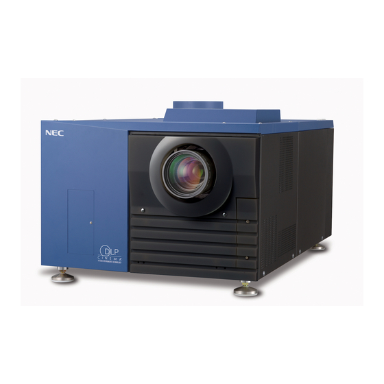
- Seite 1 ® DLP Cinema Projector NC2500S User’s Manual NEC Viewtechnology, Ltd.
- Seite 2 Precautions: Please read this manual carefully before using your Doing so may cause a fire or electric shock. NC2500S and keep the manual handy for future reference. 3. Handle the power cord carefully and avoid excessive bending. Do not place any heavy objects on the power WARNING cord.
- Seite 3 If your eyes have In Europe been exposed to this gas, please flush your eyes out with NEC Europe, Ltd. / European Technical Centre water immediately and seek immediate medical attention. Do Address: Unit G, Stafford Park 12, Telford TF3 3BJ, U.K.
- Seite 4 Important Information Précaution: lire attentivement ce manuel avant d’utiliser le 3. L’exposition aux rayons directs du soleil, à la fumée ou à NC2500S et le conserver à portée de main pour future la vapeur pourrait endommager des composants internes. référence.
- Seite 5 En Europe 2. Lorsque le corps principal est endommagé, du liquide de NEC Europe, Ltd. / European Technical Centre refroidissement peut s’échapper des parties internes. NE Adresse : Unit G, Stafford Park 12, Telford TF3 3BJ, U.K. PAS toucher ou avaler le liquide de refroidissement.
- Seite 6 GELESEN WERDEN. Reinigung Vorsichtsmaßnahmen: Lesen Sie sich dieses Handbuch 1. Schalten Sie die Stromversorgung zum Projektionskopf bitte sorgfaltig durch, bevor Sie den NC2500S benutzen, und und zum Stromversorgungsgerät der Lampe vor der bewahren Sie das Bedienungshandbuch in greifbarer Nahe Reinigung ab.
- Seite 7 Important Information Vorsichtsmasnahmen zur Vermeidung von Bränden WARNUNG: und elektrischen Schlägen 1. Schauen Sie nicht in die Linse, wenn der Projektor 1. Sorgen Sie für ausreichende Belüuftung und stellen Sie eingeschaltet ist. Dies könnte schwere Augenverletzungen zur außerdem sicher, dass die Lüftungsschlitze frei bleiben, damit Folge haben.
- Seite 8 Reparaturarbeiten am Produkt ergeben, wenden Sie sich an Ihren Händler oder an eine der folgenden Niederlassungen. In Europa NEC Europe, Ltd. / European Technical Centre Addresse: Unit G, Stafford Park 12, Telford TF3 3BJ, U.K. Telefon: +44 1952 237000 Fax-Nummer: +44 1952 237006...
-
Seite 9: Inhaltsverzeichnis
Table of Contents Table of Contents ................1 1.What’s in the Box? and the Names of the Projector Parts ..... 2 1-1. Features ..................................2 1-2. What’s in the Box? ..............................4 1-3. Names of the Projector Parts ..........................6 1-4. -
Seite 10: What's In The Box? And The Names Of The Projector Parts
® dedicated projector that supports large screen needs NEC has applied its mounting technology and leading imaging technology to newly develop lamp and optical systems as well as a cooling system to support large screen needs. • Equipped with easy to use functions (1) Lens memory function that can be operated with one touch, and lamp power memory function ®... - Seite 11 1. What’s in the Box? and the Names of the Projector Parts • DMD Face Dust Protection Structure A dust contral shield is arranged between each DMD chip of R, G and B, and the spectroscopic/condenser prism to prevent dust and dirt in the air, and oily particles in smoke associated with event halls from coming into contact with the face of the DMD and causing operating problems.
-
Seite 12: What's In The Box
1. What’s in the Box? and the Names of the Projector Parts 1-2. What’s in the Box? Check the content of the accessories. The accessories are packed into two boxes. One is for the main unit, and the other contains the lamp power supply unit. Contents of main unit box NEC2500S projector Lens holder (NC-PH01) - Seite 13 1. What’s in the Box? and the Names of the Projector Parts Contents of lamp power supply unit Box Lamp Power Supply (With power cord) Dedicated interface cable x 1 Ferrite clamp cores for AC power code x 4 Ferrite clamp core for dedicated interface cable x 1 Band x 1 ○...
-
Seite 14: Names Of The Projector Parts
1. What’s in the Box? and the Names of the Projector Parts 1-3. Names of the Projector Parts 1-3-1. Front of the projector 1. Air outlet Connects to an exhaust device to exhaust heat from the lamp. Please contact your dealer/distributor to install the exhaust device. 2. - Seite 15 1. What’s in the Box? and the Names of the Projector Parts 1-3-2. Rear of the projector 1. Air inlet Air is taken in here to provide cooling of the projector. Do not cover the air inlet. 2. Level adjusters (in four positions on bottom) In the ordinary installation, you can adjust the projector inclination at 4 positions.
- Seite 16 1. What’s in the Box? and the Names of the Projector Parts 1-3-3. Lamp power supply unit (LPSU) 1(Rear) 1. Air outlet This exhausts heat from the lamp power supply unit. 2. Main power switch This is the main power switch for the lamp power supply unit. 3.
-
Seite 17: Connection Terminals
1. What’s in the Box? and the Names of the Projector Parts 1-3-4. Connection terminals SDI-A SDI-B DVI-A DVI-B GP I/O LAN-A LAN-B CINEMA SYSTEM REMOTE RS-232C PC CARD 1. HDSDI A input terminal (SDI-A) (BNC) Connect a Video Server of Video source to this terminal. Use a 75Ω coaxial cable. 2. -
Seite 18: Control Panel
1. What’s in the Box? and the Names of the Projector Parts 1-3-5. Control panel STATUS 12 13 16 17 19 20 5 6 7 1. Remote control light reception unit This receives signals from the remote control. 2. BACKLIGHT switch Operate this switch to turn on/off the back light of the LCD screen and operation panel. - Seite 19 1. What’s in the Box? and the Names of the Projector Parts 9. 1 to 8 buttons Press the 1 to 8 buttons while depressing the CTL (MACRO) button to select titles (input signals) assigned to each button. To this projector, 100 titles at most can be registered (input signal registration). Among the registered titles, any 8 titles can be assigned to the buttons <1>...
-
Seite 20: Names On The Remote Control
1. What’s in the Box? and the Names of the Projector Parts 1-4. Names on the Remote Control 1. POWER ON button Operate this button to turn on the power to your projector. Press it three seconds or longer. When turning on the power to your projector, first set the main power switch to the main unit and the LPSU to ON, which puts your projector on standby. -
Seite 21: Inserting The Batteries
1. What’s in the Box? and the Names of the Projector Parts 11. SELECT buttons • Press the SELECT button when the menu is displayed, and a menu item can be selected. • Press the SELECT button when the menu is displayed, and a submenu will be displayed. •... - Seite 22 1. What’s in the Box? and the Names of the Projector Parts Using the remote control cable Use the remote control cable when there are objects that interrupt or obstruct the space between the remote control reception unit on the projector and the remote control, or when you are using the remote control beyond its effective range. Note that the remote control cable is connected first to the remote control, then to the projector head.
-
Seite 23: Installation And Connection
Installation and Connection 2-1. Steps for setting up and connecting Use the following steps for setting up your projector: • Step 1 Setup the screen and projector. (Contact your dealer to carry out the setup.) • Step 2 Connect cables to the image input terminals. (See page 16) Connect cables to the various control terminals. -
Seite 24: Connecting The Image Input Terminals
2. Installation and Connection 2-2. Connecting the image input terminals Your projector has four image input terminals, namely, the HDSDI A input terminal, the HDSDI B input terminal, the DVI-D A input terminal, and the DVI-D B input terminal. • HDSDI A/B input terminal (SDI A/SDI B) ------------ Inputs serial digital images from a Video Server or Video source. •... -
Seite 25: Connecting The Various Control Terminal
2. Installation and Connection 2-3. Connecting the various control terminal For control, your projector comes with such ports as the PC control terminal and the Ethernet port (RJ-45). • PC control terminal (PC CONTROL) ----- Use this terminal when controlling the projector in serial connection from a PC. •... -
Seite 26: Projection Of Images (Basic Operation)
Projection of Images (Basic Operation) 3-1. Steps of projecting images • Step 1 Turn on the power to the projector. (See page 19) • Step 2 Select the title of input signal. (See page 21) • Step 3 Adjust the position and size of the projected screen. (See page 22) •... -
Seite 27: Turning Your Projector On
3. Projection of Images (Basic Operation) 3-2. Turning your projector on The power to this projector is separated to the power to the projector head and power to the lamp. To project an image, it is necessary for both power supplies to be on. Preparation: Supply AC power to the projector head and to the lamp power supply unit. - Seite 28 3. Projection of Images (Basic Operation) Press the POWER button on the control panel of your projector three seconds or longer. Your projector is turn on, and the screen glows light about 30 seconds later. The POWER indicator of the projector lights up green.
-
Seite 29: Selecting The Title Of Input Signal
3. Projection of Images (Basic Operation) 3-3. Selecting the title of input signal This projector allows you to select pre-registered signals using the signal selection buttons on the control panel (up to 8 signals). Request your dealer/distributor for details on registering and changing titles. This section explains the steps for selecting registered signals. -
Seite 30: Adjusting The Position And The Size Of Projected Screen
3. Projection of Images (Basic Operation) 3-4. Adjusting the position and the size of projected screen 3-4-1. Displaying the test pattern Press the TEST button on the remote control. Alternatively, select the test pattern from the signal selection button. If you register the test patterns to the signal selection buttons (<1> to <8> buttons), select the test pattern according to “3-3. - Seite 31 3. Projection of Images (Basic Operation) 3-4-3. Fine adjustment of the size of the projected screen (Zoom) Press the ZOOM +/- buttons while depressing the CTL (LENS) button on the control panel of your projector as required. • When controlling with the remote control, press the ZOOM +/- button while depressing the CTL (LENS) button. 3-4-4.
-
Seite 32: Turning Your Projector Off
3. Projection of Images (Basic Operation) 3-5. Turning your projector off Press the POWER button on the projector control panel for three seconds or longer. The power to the projector is turned off. The POWER indicator and rear STATUS indicator will blink in orange (cooling state). -
Seite 33: Using Menus
Using Menus 4-1. Basic operation with adjustment menus To adjust the projector, display the menu on the LCD screen of the projector control panel. 4-1-1. Screen display The menu display screen is composed of a menu display field (the upper two lines) and a setting item display field (the bottom two lines). -
Seite 34: When In Standby
4. Using Menus When not displaying menus, the following screen is normally displayed. When in standby When the projector is in a standby state (the main power switch in on), the following is displayed. When power is turned on When the power is turned on, the following is displayed. ←... - Seite 35 4. Using Menus Press the [MENU CTL] DOWN button. The submenu “Lamp” of “Information” is displayed. The menu item can be selected by pressing the ENTER button instead of the SELECT DOWN button To return to the previous state, press the [MENU CTL] UP button, or the CANCEL button. Press the [MENU CTL] LEFT/RIGHT button to select the submenu “Version.”...
- Seite 36 4. Using Menus 4-1-3. How to enter alphanumeric characters Alphanumeric characters are entered for items, such as the title of input signal. With this projector, the characters are inputted by pressing numeric buttons on the remote control. Numeric buttons By pressing the numeric buttons, the characters can be inputted as shown in the table below. •...
-
Seite 37: Table Of Adjustment Menus
4. Using Menus 4-2. Table of adjustment menus Menus in parentheses are menus for our service personnel. Normally, these menus cannot be used. Reference Main menu Submenu Description page Title Select "Title Memory Name" Selects the title of the signal to be projected. TEST Pattern Selects the test pattern to be projected. -
Seite 38: Title Select
4. Using Menus 4-3. Title Select 4-3-1. Title select (Title Memory) Selects the title of the signal to be projected. You can register up to 100 titles. You can also assign registered titles to the Macro keys of 1 to 8 on the projector’s control panel and call them up directly using those buttons. -
Seite 39: Configuration
4. Using Menus 4-4. Configuration Please request your dealer/distributor to perform the settings. 4-4-1. Lamp Setup Adjust Adjusts the lamp output (brightness). Control the current at 0.1 A increments. ← Displays the lamp output (%) with regard to the setting. ←... -
Seite 40: Information
4. Using Menus 4-6. Information Displays the hours of lamp bulb use, the version information and error codes. 4-6-1. Lamp Displays information relating to the lamp. (Such as lamp output and the information of lamp bulb.) Output Displays the lamp brightness (output) setting. ←... -
Seite 41: Error Code
4. Using Menus 4-6-3. Usage Displays the hours of projector head, lamp, and lamp house usage, and warning display time of the lamp bulb. ← Selects the item to display. ← Displays the hours of use (H). Projector Displays the hours of projector head use. Bulb Displays the hours of use of the current lamp bulb (Lamp utilization time). - Seite 42 4. Using Menus 4-6-5. Version Displays the versions of the projector head, and the multi-media switcher (MMS) (optional). System Displays the version information of the projector head. ← Selects the item to display. ← Displays the version information. BIOS Displays the BIOS version of the projector head. Firmware Displays the firmware version of the projector head.
- Seite 43 4. Using Menus 4-6-6. IP Address Displays the IP address set in the projector head. ← Selects the item to display the IP address. ← Displays the IP address. System Displays the IP address set for the projector head (System). Cinema Displays the IP address set for the projector head (Cinema).
-
Seite 44: Maintenance Of Your Projector
Maintenance of Your Projector NOTE Please request your dealer to perform lamp replacement, filter replacement and cleaning of the projector inside. 5-1. Cleaning the Cabinet Be sure to always check that the AC power supply of the projector head and the lamp power supply unit is disconnected before carrying out maintenance of your projector. -
Seite 45: Appendix
Appendix 6-1. Troubleshooting Before asking for repair, please check your connection, settings and operation once again. If the trouble cannot be corrected, please contact your dealer/distributor for instructions or repair. 6-1-1. Problems and where to check Problem Check these items The projector cannot be turned on. -
Seite 46: Indicator Display List
6. Appendix Problem Check these items The projector cannot be operated Make sure the remote control transmission unit is facing the light reception unit on the projector. with the remote control. Check whether the batteries are still good. Replace with new batteries. Check whether there is any obstructing object between the remote control and the light reception unit on the projector. - Seite 47 6. Appendix 6-2-3. MMS STATUS indicator Indicator condition Projector condition Note Multi-media switcher (MMS) not in use. Blinking light Link error Link error. An error message is displayed in the LCD screen. Check the content of the error. Green Preparing link with Built-in multi-media Wait for a moment.
-
Seite 48: Error Code List
6. Appendix 6-3. Error code list Please inquire your dealer/distributor about action to be taken for each error code. Description is omitted for error codes 20 to 92. Error code Error message Desctiption Lamp Door Open Lamp door is open. Lamp OverTemp Temperature (lamp temperature) is abnoramal. - Seite 49 6. Appendix Error code Error message Desctiption PB FPGA Reg R/W Fail PB Serial-ID Chip Fail PB CLUT-SRAM Fail PB OvFS-SDRAM Fail PB Resizer FIR Fail PB Resizer FIFO Fail PB Other Fail FB Red RDRAM Signature Fail FB Green RDRAM Signature Fail FB Blue RDRAM Signature Fail Bulb OverTime Lamp bulb cumulative time is over.
-
Seite 50: Operation Using An Http Browser
(Example 1) When the host name of the projector has been set to “pj.nec.co.jp” http://pj.nec.co.jp/index.html is specified for the address or the entry column of the URL to access HTTP server functions. (Example 2) When the IP address of the projector is “192.168.10.10”... - Seite 51 6. Appendix 6-4-4. Structure of the HTTP server Power Controls the power to your projector. • On: Turns the power on. • Off: Turns the power off. Title List Displays titles set in the projector (such as input port, screen type, and title). Check, and the title will be changed.
-
Seite 52: Outline Drawing
6. Appendix 6-5. Outline Drawing 6-5-1. Projector head outline drawing 1100 Units: mm... - Seite 53 6. Appendix 6-5-2. Lamp power supply unit outline drawing Units: mm...
-
Seite 54: Specifications
IEC60950-1 CISPR. 22 (Note) Using any lamp other than NEC’s optional lamps will result in lower brightness compared to NEC optional lamps. If brightness is important to you, it is recommended that you use NEC’s optional lamps. NEC will post information on its homepage regarding installable lamps, other than NEC’s optional lamps. Note that NEC does not guarantee performance and reliability when lamps other than NEC’s optional lamps are installed. -
Seite 55: Caracteristiques Techniques
NEC affichera sur sa page Internet les informations concernant les lampes, autres que les lampes optionnelles NEC, pouvant être installées. Veuillez noter que NEC ne garantit pas le bon fonctionnement et la fiabilité lorsque des lampes autres que les lampes optionnelles NEC sont installées. - Seite 56 CISPR. 22 (Hinweis) Wenn Sie eine andere Lampe als die optionalen Lampen von NEC verwenden, wird im Vergleich zu den optionalen NEC-Lampen eine geringere Helligkeit erzielt. Wenn die Helligkeit für Sie ein wichtiger Faktor ist, ist es empfehlenswert, die optionalen Lampen von NEC zu verwenden.
-
Seite 57: Pin Assignment And Functions Of Terminal
Note 1: Do not use DTR and DSR signals when communicating. Note 2: Connector operations vary according to the PC control signal switch (CINEMA/SYSTEM). (When in SYSTEM, do not use RTS and CTS signals.) Internal Configuration Diagram of RS-232C Communication System Projector NC2500S PC Control Signal Switch CINEMA SYSTEM... - Seite 58 Use Ethernet 10Base-T/100Base-TX UTP (Unshielded Twist Pair cable) to connect with a video server or a PC. A switching hub exists inside, so there are no functional differences of either the LAN-A or LAN-B ports. Internal Configuration Diagram of LAN Port Projector NC2500S Cinema • Video Server...
- Seite 59 6. Appendix 6-7-4. External control connector (GP I/O) (D-Sub 37 pin) It is possible to control the projector with an external device and to control the external device from the projector using an external control connector (GP I/O: General Purpose I/O Ports). Each pin is electrically separated from the projector internal circuits by a photo-coupler.
- Seite 60 6. Appendix Input Connector GP I/O Connector Inside Projector Resist = 390 Ω Ext_GPIN_P Pin No.: Voltage applied across the pins of Ext_GPIN_P and Ext_GPIN_N should be in the range from 3.3 Vdc to 10 Vdc. Recommended Operating Current: 5mA Absolute Maximum Rating: 23mA Ext_GPIN_N...
- Seite 61 6. Appendix 6-7-5. SDI-A, SDI-B (HD-SDI input connector) (BNC) This is a signal input connector (SMPTE 292/HDSDI) for CINEMA. The SMPTE 292/HD-SDI transfers HDTV signals with 1.5 GHz digital serial signals, so use a 75 Ω coaxial cable having a thickness and characteristics higher than 5C-FB, and use a BNC for the connector.
-
Seite 62: Related Products List
Lamp house module (excluding lamp) Lamp house module NC-LH01 Lamp 4.5kW lamp NC-LP4501 6.0kW lamp NC-LP6001 Power cord (Note) NC2500S dedicated base Pedestal NC-PD01 Wireless LAN card Wireless LAN Card NWL-100 Series (Note) Touch panel Touch Panel Controler (Note) Holder arm for touch panel... - Seite 63 © NEC Viewtechnology. Ltd. 2005-2006 Printed in Japan Ver.3 06/06...
- Seite 64 Printed on recycled paper 7N8P6673...