Werbung
Verfügbare Sprachen
Verfügbare Sprachen
INSTALLATION AND MAINTENANCE INSTRUCTIONS
NFXI-BEAM AND NFXI-BEAM-T REFLECTED TYPE
PROJECTED BEAM SMOKE DETECTOR
GENERAL
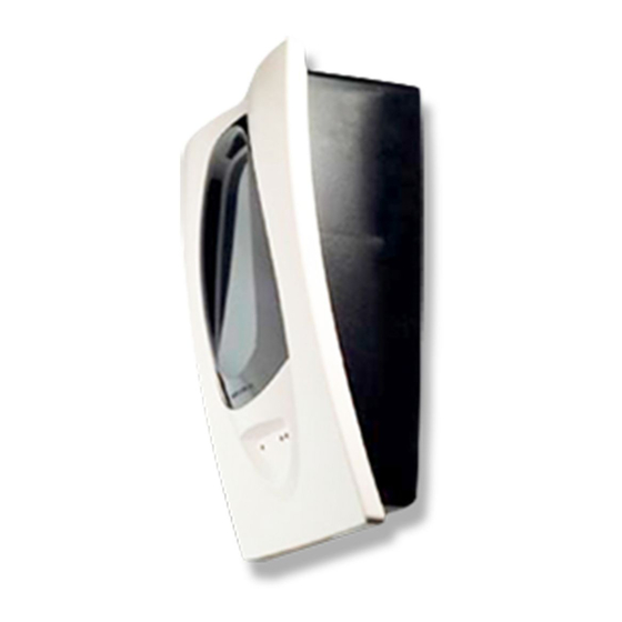
The model NFXI-BEAM is an addressable long range projected beam
smoke detector designed to provide open area protection. It consists of
a combined transmitter/receiver unit and a reflector. Smoke entering the
area between the two components causes a reduction in the signal
returned to the receiver.
When the obscuration reaches the alarm
threshold, selected at the transmitter/receiver unit, the detector
generates an alarm signal. Complete blockage of the beam causes a
fault signal. Slow changes in obscuration due to a build up of dirt or dust
on the lens of the detector are compensated for by a micro-controller
that continuously monitors the signal strength and periodically updates
the alarm and fault thresholds.
reaches its limit, the detector generates a fault signal, indicating the need
for service. After local testing is complete, the yellow LED will blink a
pattern to indicate the level of drift compensation employed during the
test (see Blinks Output by Yellow LED table at back of manual).
The model NFXI-BEAM-T includes an integral servo controlled
calibrated test filter, which allows automatic remote alarm testing.
SPECIFICATIONS
General
Range:
Sensitivity:
Maximum angular misalignment
Environmental
Temperature:
Humidity:
Mechanical
Dimensions (Without Faceplate):
Dimensions (With Faceplate):
Wiring:
Adjustment Angle:
Electrical
Voltage:
Avg. Standby Current:
Advanced Protocol Mode:
Max. Alarm Current (LED on):
Max. Fault Current (LED on):
Max. Alignment Current:
External Supply (for NFXI-BEAM-T
auto -alarm test only)
Remote Output (alarm):
PARTS LIST
Description
Transmitter/Receiver Unit
Paintable Trim Ring
Reflector (REFL6500)
Plug-in Terminal Blocks
Isolator Shunts
Orange Alignment Assistance Label
Instruction Manual
NB200-00-02
When the self-compensation circuit
5 to 70m
70 to 100m using optional
accessory 6500-LRK/BEAMLRK
Level 1 = 25% (1.25dB)
Level 2 = 30% (1.55dB)
Level 3 = 40% (2.22dB)
Level 4 = 50% (3.01dB)
Level 5 = 30% to 50% Adjusting
(Acclimate)
Level 6 = 40% to 50% Adjusting
(Acclimate)
Detector ± 0.5°
Reflector ± 10°
-30°C to 55°C
10% to 95% Relative Humidity
(Non-condensing)
229mm x 178mm x 84mm
253mm x 193mm x 84mm
0.3 mm² to 3.2 mm²
±10° Horizontal and Vertical
15 to 32 VDC (15-28.5V when
using isolators)
2mA @ 24VDC; 1 comm. every
5sec, LED flashing.
Read 16 sec. LED blink 8 sec
8.5mA
4.5mA
20mA
Voltage:
15 to 32 VDC
Current:
0.5A Max.
Voltage:
15 to 32VDC
Current:
6mA to 15mA.
Limited by 2.2KΩ resistor
Quantity
1
1
1
3
2
1
1
APPROVED ACCESSORIES
6500-LRK/BEAMLRK
Long Range Kit comprising three additional 20cm x 20cm reflectors,
which may be mounted in a square with the supplied reflector, permitting
the detector to be used for ranges from 70m to 100m.
6500-MMK/BEAMMMK
Multi-Mounting Kit allowing the NFXI-BEAM to be mounted to ceilings, or
to walls where the detector and reflector cannot be mounted within 10° of
one another.
One kit mounts either the transmitter/receiver unit or
reflector. If the transmitter/receiver is mounted on the MMK, then the
6500-SMK/BEAMSMK must be used. Note that only a single 20cm x
20cm reflector can be mounted using the MMK:
BEAMLRK is not compatible with the MMK.
6500-SMK/BEAMSMK
Surface Mounting Kit for the transmitter receiver (also used in
combination with the 6500-MMK/BEAMMMK) to give an additional 43mm
depth to assist surface mounting and to permit side entry cabling.
RTS151KEY
Remote test and annunciator accessory that enables the detector to be
tested remotely, providing test and reset functions, it has a Red LED to
indicate alarm conditions. (Note: Back-box, if required, needs to be ordered
separately - part number WM2348)
DETECTOR MOUNTING
Location
The NFXI-BEAM must be located in accordance with local standards
and guidelines, for example BS5839 part 1. For general information,
refer to the application guide for projected beam smoke detectors
available on request from your supplier.
Mounting Position
Beam detectors require a very stable mounting surface for proper
operation. A surface that moves, shifts, vibrates, or warps over time
may cause false alarm or fault conditions. Initial selection of a proper
mounting surface will eliminate nuisance alarms and fault signals. Mount
the detector on a stable mounting surface such as brick, concrete, a
sturdy load-bearing wall, support column, structural beam, or other
surface that is not expected to experience vibration or movement over
time. DO NOT MOUNT the beam detector on corrugated metal walls,
sheet metal walls, external building sheathing, external siding,
suspended ceilings, steel web trusses, rafters, non-structural beam,
joists, or other such surfaces.
tolerance to movement than the transmitter/receiver, hence in cases
where only one stable mounting surface as defined above can be used,
the transmitter/receiver unit should be mounted to the stable surface.
See specifications for maximum permissible angular misalignment;
movement outside these limits may cause nuisance alarms and faults.
Mounting Considerations
•
There must be a permanent clear line of vision between the detector
and the reflector.
•
Reflective objects should be a minimum of 380mm from the line of
sight between the detector and reflector to avoid compromise of the
protected area by reflected light.
•
Direct sunlight or strong lights into the transmitter/receiver unit
should be avoided. There should be a minimum of 10° between the
paths of the light source and the detector beam.
•
Operation of the detector through panes of glass should be avoided
if possible. If it is necessary to pass though glass, the angle between
the beam and glass should be set a minimum of 10° off perpendicular,
and operation through multiple panes should be avoided.
MOUNTING
The transmitter/receiver unit may be mounted directly to the wall, with
rear cable entry. The detector base has four primary mounting holes,
one in each corner of the base. All four holes must be used to provide
secure mounting. In order to mount the detector to the wall, the outer
cover must be removed after unscrewing it's four retaining screws.
1
The 6500-LRK/
The reflector has a much greater
I56-3878-000
Werbung
Inhaltsverzeichnis

Verwandte Anleitungen für Honeywell Notifier NFXI-BEAM-T


Inhaltszusammenfassung für Honeywell Notifier NFXI-BEAM-T
- Seite 1 INSTALLATION AND MAINTENANCE INSTRUCTIONS NFXI-BEAM AND NFXI-BEAM-T REFLECTED TYPE PROJECTED BEAM SMOKE DETECTOR GENERAL APPROVED ACCESSORIES The model NFXI-BEAM is an addressable long range projected beam 6500-LRK/BEAMLRK smoke detector designed to provide open area protection. It consists of Long Range Kit comprising three additional 20cm x 20cm reflectors, a combined transmitter/receiver unit and a reflector.
- Seite 2 Please refer to the relevant kit instructions if the transmitter/receiver is to be mounted onto the 6500-SMK/BEAMSMK or 6500-MMK/BEAMMMK allowing more flexibility for cable entry. WALL MOUNTING SCREW X 4 COVER SCREW Figure 1: Transmitter/Receiver Wall Mounting The reflector is mounted directly to the wall using all four of it’s mounting holes, one in each corner.
- Seite 3 ALIGNMENT SENSITIVITY TEST RESET Figure 6: Switch ISOLATOR SHUNTS Locations (SHOWN DISABLED) ALIGNMENT MIRROR ALIGNMENT A L I G N M E N T REMOTE P O S I T I O N GUN SIGHT POWER INDICATOR SOURCE (NFXI-BEAM-T ONLY) DIGITAL SIGNAL STRENGTH LOOP (-)
- Seite 4 At this time it is sensible to set the sensitivity of the detector using the sensitivity switch and digital display. See SENSITIVITY SELECTION for further details. Step 3. Final Gain Adjustment See figure 9. In this step, the detector electronically adjusts its internal gain one final time.
-
Seite 5: Maintenance
Test Failure Checks CHART 1: SENSITIVITY (%/m vs DISTANCE) (Assuming uniform smoke distribution) If the detector fails either the sensitivity or functional test, several steps should be taken to determine if the detector is faulty or simply needs to be re-adjusted, before returning the unit. These steps include: Level 2 1. - Seite 6 Blinks Output by Yellow LED once the Device has Passed a Local Test Percent the Number of detector has blinks drifted output <10% None <20% <30% <40% <50% <60% <70% <80% <90% <100% 0832-CPD-0330 12 EN54-12: 2002 EN54-17: 2005 NB200-00-02 I56-3878-000 Notifier Ltd, Charles Avenue, Burgess Hill, West Sussex, RH15 9UF...
- Seite 7 ISTRUZIONI DI INSTALLAZIONE E USO RIVELATORE DI FUMO A RAGGIO OTTICO MODELLO NFXI-BEAM E NFXI-BEAM-T DESCRIZIONE DELL’APPARECCHIATURA ACCESSORI APPROVATI Il modello NFXI-BEAM è un rivelatore di fumo analogico a raggio ottico a 6500-LRK/BEAMLRK lunga distanza progettato per la protezione di aree aperte. Esso consiste di “Long Range Kit”: comprende tre riflettori addizionali da 20cm x 20cm un’unità...
- Seite 8 Fare riferimento alle istruzioni dei kit 6500-SMK/BEAMSMK o 6500-MMK/ BEAMMMK se si vuol montare il rivelatore con queste configurazioni, che permettono una maggiore flessibilità nell’entrata dei cavi. VITI E TASSELLI PER FISSAGGIO A PARETE X 4 VITI CALOTTA Figura 1: Fissaggio a parete del rivelatore Il riflettore viene montato a parete utilizzando i quattro fori sugli angoli.
- Seite 9 • Assicurarsi che sia il rivelatore che il pannello riflettente siano montati rispettando le inclinazioni consentite. • Disabilitare la zona o il sistema per prevenire falsi allarmi • Assicurarsi che il rivelatore sia alimentato • Normalmente, a causa del maggiore assorbimento di corrente richiesta per l’allineamento, una sola unità...
- Seite 10 Nota: è possibile che il valore di 90 sul display non venga mai raggiunto. Ogni volta che il valore 90 viene raggiunto viene automaticamente ridotto il guadagno, rendendo così sempre più difficile ottenere alti guadagni. Qualsiasi numero è accettabile, a patto che sia il massimo raggiungibile con la regolazione fine.
-
Seite 11: Manutenzione
Grafico 1: SENSIBILITA' (%/m in funzione della distanza) 4. Il sensore può essere resettato con il pulsante RESET o a mezzo del (Distribuzione uniforme del fumo per tutta la distanza tra rivelatore e pannello riflettente) test remoto. Verifiche in caso di fallimento del test Livello 1 In caso di fallimento del test devono essere effettuate alcune verifiche per determinare se il sensore è... - Seite 12 Lampeggio del LED giallo al completamento del test locale. Livello di compensazione Numero di lampeggi raggiunto <10% Nessuno/a <20% <30% <40% <50% <60% <70% <80% <90% <100% 0832-CPD-0330 12 EN54-12: 2002 EN54-17: 2005 NB200-00-02 I56-3878-000 Notifier Italia S.r.l., Via Buozzi 55, 20097 San Donato M., Milano, Italia...
-
Seite 13: Especificaciones
INSTRUCCIONES DE INSTALACIÓN Y MANTENIMIENTO DETECTOR DE HUMO POR RAYO DEL TIPO REFLEJADO NFXI-BEAM Y NFXI-BEAM-T GENERAL ACCESORIOS APROBADOS El modelo NFXI-BEAM es un detector de humo analógico por rayo 6500-LRK/BEAMLRK proyectado de largo alcance, diseñado para proteger áreas diáfanas. Kit de largo alcance que consta de tres reflectores adicionales de 20 cm x 20 Consta de dos dispositivos: una unidad en la que se combinan transmisor y cm, lo que permite utilizar el detector para distancias entre los 70 y 100 m. - Seite 14 Consulte las instrucciones relevantes si el transmisor/receptor se va a montar en una base 6500-SMK/BEAMSMK o 6500-MMK/BEAMMMK para obtener más opciones de entrada de cable. TORNILLOS DE MONTAJE EN PARED X 4 TORNILLOS DE LA TAPA X 4 Figura 1: Montaje en pared del transmisor/receptor El reflector se monta directamente en la pared utilizando los cuatro orificios de montaje, uno en cada esquina.
- Seite 15 · Asegúrese de que el detector y el reflector están instalados dentro de los parámetros operativos de los ángulos de ajuste. · Anule la zona o sistema para evitar alarmas no deseadas antes de aplicar la alimentación. · Asegúrese de que el detector está “ACTIVADO”, alimentación en “ON”. ·...
- Seite 16 Es recomendable ajustar ahora la sensibilidad del detector con el botón de sensibilidad y la pantalla digital. Véase la sección SELECCIÓN DE SENSIBILIDAD para más detalles. Fase 3. Ajuste final de ganancia Véase la figura 9. En esta fase, el detector ajusta electrónicamente su ganancia interna por última vez.
-
Seite 17: Mantenimiento
GRÁFICA 1: SENSIBILIDAD (%M vs. DISTANCIA) Comprobaciones ante fallo de prueba (assumiento una distribución uniforme del humo) Si el detector falla la prueba funcional o la de sensibilidad, se deben realizar varias acciones para determinar, antes de devolverlo, si está defectuoso o simplemente necesita reajustarse. - Seite 18 Número de la deriva del parpadeos detector <10% Ninguno <20% <30% <40% <50% <60% <70% <80% <90% <100% 0832-CPD-0330 12 EN54-12: 2002 EN54-17: 2005 NB200-00-02 I56-3878-000 Notifier Espana S.A. Honeywell Life Safety Iberia, S.L. C/ Pau Vila, 15-19 08911 Barcelona, Espana.
-
Seite 19: Spezifikation
INSTALLATIONS- UND WARTUNGSANLEITUNG LINEARER RAUCHMELDER NFXI-BEAM UND NFXI-BEAM-T MIT PRISMEN-REFLEKTOR ALLGEMEIN Lineare Rauchmelder NFXI-BEAM ringbusgespeister VOM HERSTELLER ZUGELASSENES ZUBEHÖR Langstrecken-Melder und wird zur Überwachung von offenen Bereichen eingesetzt. Der Melder besteht aus einer Sender-/Empfänger-Einheit sowie 6500-LRK/BEAMLRK einem Prismen-Reflektor. Die Auslösung des Melders erfolgt bei Langstrecken-Zubehör, bestehen drei... - Seite 20 Die Verkabelung des Melders wird durch das Installationszubehör 6500- SMK/BEAMSMK oder 6500-MMK/BEAMMMK erleichtert. Weiter-führende Informationen sind der jeweiligen Installationsanleitung zu entnehmen. SCHRAUBEN ZUR WANDBEFESTIGUNG GEHÄUSESCHRAUBEN Abbildung 1: Wandmontage der Sender-/Empfänger-Einheit Der Prismen-Reflektor- wird mittels der vier Befestigungslöcher in jeder 1 2 3 4 1 2 3 4 1 2 3 4 Ecke, direkt auf der Montagefläche befestigt.
- Seite 21 • Stellen Sie sicher, dass sich keine Objekte zwischen dem Melder und dem Prismen-Reflektor befinden. Weiterhin dürfen sich im näheren Umfeld seitlich zur Strahlachse (mindestens 380mm) keine reflektierenden Objekte befinden. • Stellen Sie sicher, dass die Achswinkel des Melders und des Prismen-Reflektors eingehalten werden.
-
Seite 22: Einstellung Der Empfindlichkeit
Schritt 3. End-Verstärkungseinstellung Siehe Abbildung 9. In diesem Schritt erfolgt die endgültige Einstellung der Verstärkung. Für diesen Schritt ist es erforderlich, das Gehäuseoberteil wieder zu montieren, AUGE da sich die Empfangseigenschaften des reflektierten Lichts hierdurch verändern. Montieren Sie das Gehäuseoberteil des Melders. Das Gehäuseoberteil wird mittels der vier Gehäuseschrauben in den Ecken befestigt. -
Seite 23: Wartung
Diese beinhaltet folgende Schritte: KENNLINIE 1: MELDEREMPFINDLICHKEIT (%/m) vs 1. Überprüfen Sie alle elektrischen Anschlussleitungen, sowie die UBERWACHTUNGSSTRECKE Spannungsversorgung des Melders. 2. Stellen Sie sicher, dass der Strahlenweg nicht durch ein Hindernis versperrt ist oder durch Fremdlichtquellen inkl. reflektierende bzw. Ebene 2 glänzende Oberflächen gestört wird. - Seite 24 Blinkmodus der gelben LED nach einem lokalen Meldertest: Anzahl des Prozentwert Melderblinkens Driftkompensation <10% Kein <20% <30% <40% <50% <60% <70% <80% <90% <100% 0832-CPD-0330 12 EN54-12: 2002 EN54-17: 2005 NB200-00-02 I56-3878-000 Notifier Sicherheitssysteme GmbH, Stadionring 32, 40878 Ratingen, Deutschland...