Inhaltsverzeichnis
Werbung
Verfügbare Sprachen
Verfügbare Sprachen
Quicklinks
VS Vereinigte Spezialmöbelfabriken GmbH & Co. KG
Hochhäuser Straße 8 · 97941 Tauberbischofsheim · Tel.: 09341/880 · vs@vs-moebel.de
http://links.vs-service.com/downloads/70-195_V04_DEENFR_Serie_1100-175959.pdf
70-195 V04 000918
MONTAGEANLEITUNG:
Serie 1100.
Bitte sorgfältig aufbewahren!
INSTRUCTIONS DE MONTAGE:
Serie 1100.
A conserver soigneusement !
70-195 V04 000918
ASSEMBLY INSTRUCTION:
Serie 1100.
Please store this document in a safe place!
70-195 V04 000918
Werbung
Kapitel
Inhaltsverzeichnis

Verwandte Anleitungen für VS Vereinigte Spezialmöbelfabriken 1100 serie


Inhaltszusammenfassung für VS Vereinigte Spezialmöbelfabriken 1100 serie
- Seite 1 VS Vereinigte Spezialmöbelfabriken GmbH & Co. KG Hochhäuser Straße 8 · 97941 Tauberbischofsheim · Tel.: 09341/880 · vs@vs-moebel.de http://links.vs-service.com/downloads/70-195_V04_DEENFR_Serie_1100-175959.pdf 70-195 V04 000918 70-195 V04 000918 MONTAGEANLEITUNG: ASSEMBLY INSTRUCTION: Serie 1100. Serie 1100. Bitte sorgfältig aufbewahren! Please store this document in a safe place! 70-195 V04 000918 INSTRUCTIONS DE MONTAGE: Serie 1100.
-
Seite 2: Inhaltsverzeichnis
Inhalt. Warnhinweise 1. Allgemeine Informationen Bedienungsanleitung genau lesen und aufheben! Im Ver- 2. Montage der Tischplatte stellbereich 68-117 cm darf keine Beeinträchtigung durch 3. Elektrifizierung der höhenflexiblen Arbeitsstation Fremdkörper/Gegenstände bestehen. Max. Belastung der Ausrichten der flexiblen Arbeitsstation Tischplattenaußenkante beträgt ca. 75 kg. Werden zwei Ti- 4. -
Seite 3: Montage Der Tischplatte
2. Montage der Tischplatte Tischplatte (1) senkrecht am Tischrahmen in die dafür vorge- sehenen Aussparungen (2) einhängen. Tischplatte 90° nach hinten absenken. Durch Verdrehung der Verriegelungswelle (3) die Tischplatte am Tischrahmen sichern. -
Seite 4: Elektrifizierung Der Höhenflexiblen Arbeitsstation Ausrichten Der Flexiblen Arbeitsstation
3. Elektrifizierung der höhenflexiblen Anbringen des Bedienteils. Bedienteil in die angebrachte Arbeitsstation. Ausrichten der Halterung (1) einstecken (Unterseite Tischplatte). Das Kabel flexiblen Arbeitsstation durch die im Tischrahmen befindliche Bohrung (2) führen. Stromversorgung. Netzkabel in Netzanschluss 230 V der Durch die vorhandenen Clipse (3) führen und den DIN-Pol- Hubsäule einstecken. -
Seite 5: Befestigung Der Screen-Blende
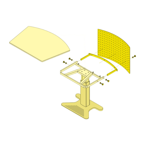
4. Befestigung der Screen-Blende Halterung (5) in den Tischrahmen stecken. Mit 4 Rändel- schrauben (M6 x 20) (6) und 4 Distanzscheiben seitlich am Tischrahmen befestigen. Screen-Blende (7) positionieren und mit 3 Rändelschrauben (8) (M6 x 20) und Distanzscheiben befestigen. -
Seite 6: Befestigung Elektrifizierung Einzelarbeitsplatz
5. Befestigung Elektrifizierung Einzelarbeitsplatz Die Elektrifizierungseinheit (1) in die in der Hubsäule bereits vormontierten Schrauben (2) (M5 x 16) einhängen. Mittels 2 Schrauben (3) (M5 x 16) beidseitig sichern. -
Seite 7: Befestigung Elektrifizierung Doppelarbeitsplatz
6. Befestigung Elektrifizierung Doppelarbeitsplatz Bereits montiert! Ansonsten Befestigung wie Einzelarbeits- platz. -
Seite 8: Befestigung Vertikale Kabelführung
7. Befestigung vertikale Kabelführung Vertikale Kabelkette (1) an den am Tischrahmen vormontier- ten Kabelhalter (2) einclipsen. Falls Arbeitsplatz elektrifiziert: Blenden (3) der Elektrifizie- rungseinheit abclipsen. Vertikale Kabelkette (1) an den am Tischrahmen und an den Rohren der Elektrifizierungseinheit vormontierten Kabelhalter (2) einclipsen. Blenden wieder an- bringen. -
Seite 9: Befestigung Cpu-Halter (Für Trapez- Und Rechtecktisch)
8. Befestigung CPU-Halter (für Trapez- und Rechtecktisch) Abdeckkappen (1) an den Rohrenden der Elektrifizierungs- einheit entfernen. Befestigungsblech (2) im Rahmen einste- cken und mittels Schrauben (M8 x 16) gegen Abzug sichern. CPU-Drahtkorb (3) mittels Zylinderschraube (M6 x 20) und Klemmleiste (4) an das Befestigungsblech anschrauben. Montage sowohl vertikal als auch horizontal möglich! -
Seite 10: Höhenverstellung
9. Höhenverstellung [Bild 1] Bedienung mit Bedienteil für Säule elektrisch Komfortsteuerung. [Bild 2] Bedienung mit Bedienteil für Säule elektrisch. [Bild 3] Bedienung mit Handkurbel für Säule mecha- nisch. -
Seite 11: General Information
Contents. Warning 1. General information Please read the operating instructions very carefully and 2. Assembly of the table top keep in a safe place. In the area of adjustment from 68– 3. Electrification of the variable height work station 117 cm, there must not be any obstruction by foreign bodies Levelling the flexible work station or objects. -
Seite 12: Assembly Of The Table Top
2. Assembly of the table top Hang the table top (1) vertically in the opening (2) provided for it on the table frame. Lower the table top backwards by 90°. Secure the table top to the table frame by twisting the locking spindle (3). -
Seite 13: Electrification Of The Variable Height Work Station Levelling The Flexible Work Station
3. Electrification of the variable height Attachment of the control unit. Insert the control unit in- work station. Levelling the flexible to the holder (1) provided (on the underside of the table work station. top). Feed the cable through the hole (2) provided in the Power supply. -
Seite 14: Securing The Screen-Panel
4. Securing the screen-panel Insert the holder (5) into the table frame. Secure with 4 (M6 x 20) knurled screws (6) and 4 spacers to the side of the ta- ble frame. Position the screen panel (7) and secure with 3 (M6 x 20) knurled screws (8) and spacers. -
Seite 15: Attachment Of The Electrification Single Work Place
5. Attachment of the electrification single work place Hang the electrification unit (1) into the (M5 x 16) screws (2) already installed in the lifting column. Secure on both sides with 2 (M5 x 16) screws (3). -
Seite 16: Attachment Of The Electrification Double Work Place
6. Attachment of the electrification double work place Already installed! Otherwise secure just like single work place. -
Seite 17: Attachment Of Vertical Cable Guide
7. Attachment of vertical cable guide Clip the vertical cable chain (1) into the cable holders (2) al- ready installed on the table frame. Should the work place be electrified: Unclip the screens (3) of the electrification unit. Clip the vertical cable chain (1) into the cable holders (2) already installed on the table frame and the tubes of the electrification unit. -
Seite 18: Securing The Cpu Holder (For Trapezoid And Rectangular Tables)
8. Securing the CPU holder (for trape- zoid and rectangular tables) Remove the cover caps (1) on the ends of the tubes of the electrification unit. Insert the fixing plate (2) into the frame and secure with (M8x16) screws. Screw the CPU wire basket (3) to the fixing plate using (M6 x 20) cheese-headed screws as well as the terminal strip (4). -
Seite 19: Height Adjustment
9. Height adjustment [Fig. 1] Operation with controller for electrical column Comfort-controller. [Fig. 2] Operation with controller for electrical column. [Fig. 3] Operation with winding handle for mechanical column. -
Seite 20: Généralités
Sommaire. Attention : 1. Généralités Lire attentivement et conserver le mode d’emploi! A l’intérieur 2. Montage du plateau de table de la plage de réglage entre 68-117 cm faire attention à ce 3. Electrification de la station de travail qu’aucun objet n’entrave au réglage de la hauteur. La charge à... -
Seite 21: Montage Du Plateau De Table
2. Montage du plateau de table Accrocher le plateau de table (1) verticalement dans les en- coches (2) du cadre de la table prévues à cet usage. Rabattre le plateau vers l’arrière sur un angle de 90°. Assurer le pla- teau de table au cadre en tournant la tige de verrouillage (3). -
Seite 22: Electrification De La Station De Travail À Hauteur Flexible Positionnement De La Station De Travail Flexible
3. Electrification de la station de travail Fixation de la console de commande. Introduire la console à hauteur flexible. Positionnement de de commande dans le support (1) prévu à cet usage (sous le la station de travail flexible plateau de table). Introduire le câble dans la perforationc (2) Alimentation en courant. -
Seite 23: Fixation Du Voile Cache Moniteur
4. Fixation du voile cache moniteur Introduire le support (5) dans le cadre de la table. Fixer laté- ralement au moyen des 4 vis moletées (M6 x 20) (6) et des 4 rondelles d’écartement. Positionner le voile cache moniteur (7) et fixer à l’aide des 3 vis moletées (8) (M6 x 20) et des rondelles d’écartement. -
Seite 24: Fixation Du Bloc D'électrification Pour Poste De Travail Simple
5. Fixation du bloc d’électrification pour poste de travail simple Accrocher l’unité électrique (1) sur les vis pré-montées (2) (M5 x 16) situées sur la colonne de levage. Bloquer au moyen des 2 vis (3) (M5x16) des deux côtés. -
Seite 25: Fixation Du Bloc D'électrification Pour Poste De Travail Double
6. Fixation du bloc d’électrification pour poste de travail double Livré monté! Sinon procéder comme pour le poste de travail simple. -
Seite 26: Fixation De La Colonne Verticale Articulée De Guidage De Câbles
7. Fixation de la colonne verticale arti- culée de guidage de câbles Accrocher la colonne verticale articulée de guidage de câ- bles (1) sur les supports pré-montés (2) situés sur le cadre de la table. En cas d’électrification du poste de travail: Détacher le voile (3) de l’unité... -
Seite 27: Fixation Du Sopport Pour Disque Dur (Pour Tables Rectangulaire Et Trapézoïdale)
8. Fixation du sopport pour disque dur (pour tables rectangulaire et trapé- zoïdale) Retirer les embouts (1) situés à l’extrémité des traverses tu- bulaires de l’unité électrique. Accrocher la tôle de fixation (2) dans le cadre et bloquer avec les vis (M8 x 16). Visser la grille pour disque dur (3) à... -
Seite 28: Réglage De La Hauteur
9. Réglage de la hauteur [Fig. 1] Colonne de levage électrique avec console de commande. Commande confortable. [Fig. 2] Colonne de levage électrique avec console de commande. [Fig. 3] Colonne de levage mécanique avec manivelle.