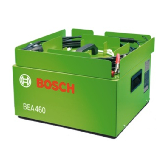
Inhaltszusammenfassung für Bosch BEA 460
- Seite 1 BEA 460 de Instandsetzungsanleitung en Servicing instructions Bosch-Emissions-Analyse Bosch-Emissions-Analysis 1 689 975 210 2008-11-07...
-
Seite 2: Inhaltsverzeichnis
2 | BEA 460 | Inhaltsverzeichnis Benutzerhinweise Dokumentation BEA 460 Sicherheitshinweise Zielgruppe Abkürzungen Übersicht Komponenten Anschlussübersicht und Einstellung Ringkerntrafo Stromlaufplan Schnittstellen Verschlauchung Gaslaufplan Wartung Eichpflicht Fehlersuche und Instandsetzung 1 689 975 210 2008-11-07 Robert Bosch GmbH... -
Seite 3: Benutzerhinweise
Vorsicht - Zerstörung elektrotechnischer Achtung – warnt vor möglicherweise schädlichen Bauteile! Situationen, bei der BEA 460, der Prüfling oder eine Bei unsachgemäßer Handhabung von Leiter- Sache in der Umgebung beschädigt werden könnte. platten, können elektrostatisch gefährdete Bauteile beschädigt werden. -
Seite 4: Übersicht
4 | BEA 460 | Übersicht Übersicht Komponenten 1 Abdeckhaube 11 Abgassonde 2 Trafo 12 Systemtester 3 Gehäuse 13 Fernbedienung 4 Magnetventil 14 Fernsteuerempfänger 5 Grobfilter 15 USB-Bluetooth-Adapter 6 Kondensatabscheider 16 Seriell-Bluetooth-Adapter 7 O2-Sensor 17 Mainboard 8 Vakuumpumpe 18 DTM... -
Seite 5: Anschlussübersicht Und Einstellung Ringkerntrafo
Übersicht | BEA 460 | 5 BEA 460 | 5 Anschlussübersicht und Einstellung Ringkerntrafo Netzan- Anschlussleitung Ringkerntrafo 260 V schluss 230 V 275 V 110 V 260 V -15 V 245 V 230 V +15 V 215 V 125 V... -
Seite 6: Stromlaufplan
6 | BEA 460 | Übersicht Stromlaufplan + 12 V 260 V 1 14,5 VAC + 12 V + 12 V 2 11 VAC 230 V 110 V + 8 V 3 0 V -15 V 4 14,5 VAC + 5 V... -
Seite 7: Schnittstellen
Übersicht | BEA 460 | � BEA 460 | � | � Schnittstellen Die Schnittstelleneinstellungen sind in der Einbauan- leitung 1 689 978 427 dargestellt. Verschlauchung Teilesatz Verschlauchung siehe Ersatzteilliste 1 689 973 324. Robert Bosch GmbH 1 689 975 210... -
Seite 8: Gaslaufplan
8 | BEA 460 | Übersicht Gaslaufplan 459869_06Ht NO₂* O₂ Messgas optional Kondensat Aktivkohlefilter Frischluft Abgas-Mess-Modul Prüfgas Abgassonde Drucksensor Grobfilter Prüfgaseingang Gaspumpe Kondensatabscheider Messgas-, Frischluft- und Prüfgasausgang Kondensatpumpe Messkammer Kondensatausgang Magnetventil Stickstoffmonoxid-Sonde Stickstoffdioxid-Sonde Sauerstoff-Sonde Rückschlagventil 1 689 975 210 2008-11-07... -
Seite 9: Wartung
Zeit in der Überarbeitung. Mit der nächsten Aktualisierung der Instandsetzungsanlei- Zeitraum tung für BEA 460 wird eine neue Struktur eingeführt. Die BEA muss halbjährlich von fachkundigen Personen gewartet werden. Wird bei diesen Arbeiten ein amtli- ches Prüfsiegel verletzt, muss die ordnungsgemäße und sachkundige Instandsetzung durch den autorisierten Kundendienst durchgeführt, bestätigt und eine neue Ei-... - Seite 10 10 | BEA 460 | Contents User instructions Documentation BEA 460 Safety instructions Target group Abbreviations Overview Components Connection overview and setting toroidal transformer Cicuit diagram Interfaces Hose connection Gas circuit diagram Servicing 1� Mandatory calibration Trouble-shooting and maintanance 1�...
-
Seite 11: User Instructions
¶ Keep all appropriate land regulations. Important – warns of a potentially hazardous situa- tion in which the BEA 460, the test sample or other Caution - Destruction of electrotechnical object in the vicinity could be damaged. units! During inappropriate handling of printed... -
Seite 12: Overview
12 | BEA 460 | Overview Overview Components 1 Hood 11 Exhaust-gas analyzer module 2 Transformer 12 System tester 3 Housing 13 Remote control transmitter 4 Solenoid valve 14 Remote control receiver 5 Coarse filter 15 Bluetooth USB adapter 6 Condensate separator... -
Seite 13: Connection Overview And Setting Toroidal Transformer
Overview | BEA 460 | 13 BEA 460 | 13 | 13 Connection overview and setting toroidal transformer Mains Connecting cabel toroidal transformer 260 V voltage 230 V 275 V 110 V 260 V -15 V 245 V 230 V... -
Seite 14: Cicuit Diagram
14 | BEA 460 | Overview Cicuit diagram + 12 V 260 V 1 14,5 VAC + 12 V + 12 V 2 11 VAC 230 V 110 V + 8 V 3 0 V -15 V 4 14,5 VAC... -
Seite 15: Interfaces
Overview | BEA 460 | 15 BEA 460 | 15 | 15 Interfaces The interface settings are shown in the installation instructions 1 689 978 427. Hose connection Parts set for the hose connection see spare parts list 1 689 973 324. -
Seite 16: Gas Circuit Diagram
16 | BEA 460 | Overview Gas circuit diagram 459869_06Ht NO₂* O₂ Sample gas optional Condensate Activated charcoal filter Fresh air Exhaust-gas analyzer module Test gas Exhaust gas sampling probe Pressure sensor Coarse filter Test gas inlet Gas pump Condensate separator... -
Seite 17: Servicing
Servicing | BEA 460 | 1� BEA 460 | 1� | 1� Servicing Trouble-shooting and maintanance Mandatory calibration The regulations governing the calibration of exhaust- The trouble-shooting and maintanance are iden- gas analyzers in the specific country of use must be tical to the BEA 450. - Seite 18 Robert Bosch GmbH Diagnostics Franz-Oechsle-Straße 4 73207 Plochingen DEUTSCHLAND www.bosch.com bosch.prueftechnik@bosch.com 1 689 975 210 | 2008-11-07...


