Inhaltsverzeichnis
Werbung
Verfügbare Sprachen
Verfügbare Sprachen
Werbung
Kapitel
Inhaltsverzeichnis

Verwandte Anleitungen für Herth+Buss 95980775

Inhaltszusammenfassung für Herth+Buss 95980775
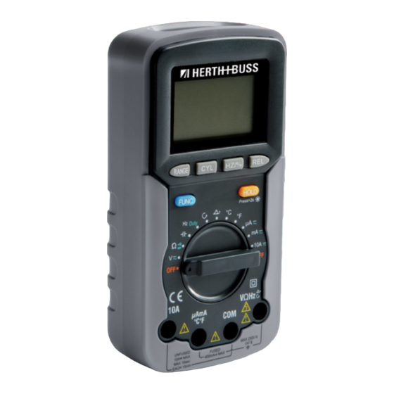
- Seite 1 E LPA RTS Multimeter Bedienhinweis...
-
Seite 2: Inhaltsverzeichnis
Bedienhinweis 95980775 Inhalt Kapitel Seite Einleitung Sicherheitshinweise Symbole Anleitung Erklärung der LCD-Anzeige Allgemeine Spezifikationen Bedienung Messung des Schließwinkels Drehzahlmessung Wartung Auswechseln der Batterie und Sicherung Spezifikation www.herthundbuss.com... -
Seite 3: Bedienhinweis
Bedienhinweis 95980775 Einleitung Das 3 ⁄ -stellige Digitalmultimeter ist ein Autorange-Universalmessgerät für KFZ- Anwendungen. Neben den Funktionen eines normalen Universalmessgerätes kann es auch Drehzahl, Schließwinkel, Tastverhält- nis, Temperatur (°C/°F) usw. messen. Es ist ein nützliches Messinstrument, das ideal für Reparatur- und Instandhaltungsarbeiten an Kraftfahrzeugen geeignet ist. -
Seite 4: Sicherheitshinweise
Bedienhinweis 95980775 Sicherheitshinweise Das Messinstrument ist nach IEC 61010 für 7. Bei Stromstärkemessungen vor dem elektronische Messinstrumente mit Mess- Anschließen des Messinstruments in kategorie CAT II und Verschmutzungsgrad 2 der Schaltung Strom abschalten. Daran entwickelt worden. denken, das Messinstrument in Reihe zu schalten. -
Seite 5: Symbole
Bedienhinweis 95980775 16. In der Betriebsart „Relative“ (es erscheint Vorsicht: Zur Vermeidung von Schäden am das Symbol „REL “) oder „Data Hold“ (es Mess instrument oder dem zu prüfenden Ge erscheint das Symbol „ “) ist Vorsicht rät folgende Richtlinien beachten: geboten, weil gefährliche Spannung vor-... -
Seite 6: Anleitung
Bedienhinweis 95980775 Anleitung 3. CYLTaste (Zylinder) Mit dieser Taste kann die Zahl der Motorzy- linder gewählt werden. 4. FUNCTaste (Funktion) Bei Spannungs- oder Stromstärkemessun- gen kann mit dieser Taste AC oder DC ge- wählt werden. Wenn der Drehschalter in Stellung ist, kann mit dieser Taste zwischen folgenden Messungen gewählt werden: Wi-... - Seite 7 Bedienhinweis 95980775 10. HOLDTaste Eingebauter Summer Durch kurzes Drücken dieser Taste bleibt der 1. Beim Drücken einer Taste gibt der einge- aktuelle Messwert erhalten, das Messinst- baute Summer einen Piepton ab, wenn rument bleibt im Modus „Data Hold“ und der Tastendruck Wirkung erzielt hat.
-
Seite 8: Erklärung Der Lcd-Anzeige
Bedienhinweis 95980775 Erklärung der LCDAnzeige Symbol Bedeutung Durchgangsprüfung ist gewählt. Diodenprüfung ist gewählt. USB-Kommunikation (serielle Schnittstelle) ist aktiviert. (optional) Autorange-Modus ist gewählt. Modus „Relative Messungen“ ist aktiviert. „Data Hold“-Funktion ist aktiviert. Negativ-Zeichen Wechselspannung Gleichspannung Die Batterie ist schwach und sollte umgehend ausgewechselt werden. -
Seite 9: Allgemeine Spezifikationen
Bedienhinweis 95980775 Symbol Bedeutung Einheiten auf dem LCD-Display mV, V Einheit der Spannung, mV: Millivolt; V: Volt, 1 V = 10 µA, mA, A Einheit der Stromstärke, µA: Mikroampere, mA: Milliampere; A: Ampere 1 A = 10 mA = 10 µA... -
Seite 10: Bedienung
Bedienhinweis 95980775 Bedienung Nutzung der Betriebsart 2. Zum Deaktivieren der manuellen Mess- „Relative Messungen“ bereichswahl die RANGE-Taste drücken Mit Wahl der Betriebsart „Relative Messun- und länger als zwei Sekunden halten. Das gen“ speichert das Messinstrument den ak- Messinstrument schaltet wieder auf Auto- tuellen Messwert als Bezugswert für weitere... - Seite 11 Bedienhinweis 95980775 Anmerkung: Anmerkung: Zur Vermeidung eines Stromschlages oder Wenn Sie den Wert der zu messenden Strom- Schäden am Messinstrument keine Gleich- stärke nicht vorher wissen, den höchsten spannung über 250 V oder Wechselspan- Messbereich wählen und dann schrittweise nung über 250 V RMS messen, auch wenn verringern, bis eine zufriedenstellende Auf- dies möglich ist.
- Seite 12 Bedienhinweis 95980775 Durchgangsprüfung Frequenzmessung 1. Die schwarze Prüfleitung in den COM- 1. Die schwarze Prüfleitung in den COM- Eingang und die rote Prüfleitung in den Eingang und die rote Prüfleitung in den -Eingang stecken. (Anmerkung: -Eingang stecken. 2. Bereichsschalter auf Hz Duty stellen.
- Seite 13 Bedienhinweis 95980775 Anmerkung: Kapazitätsmessung Die Spannung des Eingangssignals muss 1. Die schwarze Prüfleitung in den COM- zwischen 3 und 10 Vp-p liegen, und die Fre- Eingang und die rote Prüfleitung in den quenz des Eingangssignals muss weniger -Eingang stecken. (Anmerkung: als 10 kHz betragen.
-
Seite 14: Messung Des Schließwinkels
Bedienhinweis 95980775 Messung des Schließwinkels 1. Die schwarze Prüfleitung in den COM- Anmerkungen: Eingang und die rote Prüfleitung in den 1. Die Eingangsspannung muss zwischen -Eingang stecken. (Anmerkung: 3 und 50 Vp liegen. Ist die Spannung Die Polarität der roten Leitung ist positiv zu niedrig, kann keine Winkelmessung „+“.) -
Seite 15: Drehzahlmessung
Bedienhinweis 95980775 Drehzahlmessung 1. Die schwarze Prüfleitung in den COM- niedrig, kann keine Drehzahlmessung Eingang und die rote Prüfleitung in den durchgeführt werden. -Eingang stecken. (Anmerkung: 2. Die Stabilität der Messwertanzeige nimmt Die Polarität der roten Leitung ist positiv ab, wenn die Drehzahl des Motors zu „+“.) -
Seite 16: Wartung
Bedienhinweis 95980775 Wartung Auswechseln der Batterie und Sicherung Achtung! Mit Ausnahme des Auswechselns von Batte Achtung! rie und Sicherung nie versuchen, das Mess Zur Vermeidung fehlerhafter Messwerte, die instrument zu reparieren oder instand zu einen Stromschlag oder Verletzungen zur setzen, wenn Sie nicht entsprechend quali... -
Seite 17: Spezifikation
Bedienhinweis 95980775 Spezifikation Die Messgenauigkeit ist für einen Zeitraum genauigkeit erfolgen in folgender Form: ± von einem Jahr nach Kalibrierung bei 18 bis ([% des Messwerts]+[Anzahl der Ziffern mit 28 °C und einer relativen Feuchtigkeit von dem niedrigsten Stellenwert]) <75 % angegeben. Die Angaben zur Mess-... - Seite 18 Bedienhinweis 95980775 Gleichstromstärke DC Messbereich Auflösung Messgenauigkeit 400 µA 0,1 µA ± (1,2 % + 3) 4000 µA 1 µA ± (1,2 % + 3) 40 mA 10 µA ± (1,2 % + 3) 400 mA 100 µA ± (1,2 % + 3) 1 mA ±...
- Seite 19 Bedienhinweis 95980775 Widerstand Messbereich Auflösung Messgenauigkeit 400 Ω 0,1 Ω ± (1,0 % + 5) 4 kΩ 1 Ω ± (1,0 % + 3) 40 kΩ 10 Ω ± (1,0 % + 3) 400 kΩ 100 Ω ± (1,0 % + 3) 4 MΩ...
- Seite 20 Bedienhinweis 95980775 Kapazität (Modus „Relative Messungen“ nutzen) Messbereich Auflösung Messgenauigkeit 50 nF 0,01 nF ± (4,0 % + 5) 500 nF 0,1 nF 5 µF 0,001 µF 50 µF 0,01 µF 100 µF 0,1 µF ± (8,0 % + 5) Überlastungsschutz:...
- Seite 21 Bedienhinweis 95980775 Schließwinkel Zylinder Messbereich Auflösung Messgenauigkeit 0 bis 180° 0,1° ± (2,5 % + 5) 0 bis 120° 0,1° ± (2,5 % + 5) 0 bis 90° 0,1° ± (2,5 % + 5) 0 bis 72° 0,1° ± (2,5 % + 5) 0 bis 60°...
- Seite 22 Operating Instruction 95980775 Contents Chapter Page Introduction Safety information Symbols Instruction LCD explanation General specification Operation instruction Measuring Dwell Angle Measuring Engine Tach Maintenance Replacing the Battery and Fuse Specification www.herthundbuss.com...
-
Seite 23: Introduction
Operating Instruction 95980775 Introduction This 3 ⁄ -digit digital multimeter is an auto- range automotive multimeter. Besides the features of a normal multimeter, it can also be used to measure RPM, dwell angle, duty cycle, temperature (C;oF), and etc. It is a use- ful and ideal measurement tool for automo- tive repair and service. -
Seite 24: Safety Information
Operating Instruction 95980775 Safety information This meter has been designed according to 9. Use caution when working above 30V ac IEC-61010 concerning electronic measuring rms, 42V peak, or 60V dc. Such voltages instruments with a measurement category pose a shock hazard. -
Seite 25: Symbols
Operating Instruction 95980775 18. CATII – Measurement Category II is for Caution measurements performed on circuits To avoid possible damage to the meter or directly connected to low voltage instal- to the equipment under test, follow these lation. (Examples are measurements on... -
Seite 26: Instruction
Operating Instruction 95980775 Instruction 4. “FUNC” Button In voltage or current measurements, this but- ton can be used to select ac or dc function. When the rotary switch is in “ ” position, this button can be used to select resistance, diode or continuity measurement. - Seite 27 Operating Instruction 95980775 10. “HOLD” Button Builtin Buzzer Press this button momentrily to freeze the 1. When you press a button, the built-in present reading, the meter stays in Data buzzer will give a beep if this press is ef- Hold mode, and “...
-
Seite 28: Lcd Explanation
Operating Instruction 95980775 LCD explanation Symbol Meaning Continuity test is selected. Diode test is selected. USB serial port communication is enabled. (optional) Autorange mode is selected. Relative mode is active. Data Hold is enabled. Negative sign AC voltage DC voltage The battery is low and should be replaced immediately. -
Seite 29: General Specification
Operating Instruction 95980775 Symbol Meaning Units on the LCD mV, V Voltage unit, mV: Millivolt; V: Volt, 1 V = 10 µA, mA, A Current unit, µA: Microamp, mA: Milliamp; A: Ampere 1 A = 10 mA = 10 µA Ω, kΩ, MΩ... -
Seite 30: Operation Instruction
Operating Instruction 95980775 Operation instruction Using Relative Mode Data Hold Mode Selecting relative mode causes the meter to Press the “HOLD” button to hold the present store the present reading as a reference for reading on the display, “ ” appears on the subsequent measurements. - Seite 31 Operating Instruction 95980775 Measuring Current 1. Connect the black test lead to the COM jack. 3. Connect the test leads across the load to If the current to be measured is less than be measured. 400mA, connect the red test lead to the 4.
- Seite 32 Operating Instruction 95980775 Diode 1. Connect the black test lead to the COM Measuring Duty Cycle jack, and the red test lead to the 1. Connect the black test lead to the COM jack. (Note: The polarity of the red lead is jack, and the red test lead to the positive “+”.)
- Seite 33 Operating Instruction 95980775 Measuring Temperature Measuring Capacitance To avoid possible damage to the meter or 1. Connect the black test lead to the COM other equipment, remember that while the jack, the red test lead to the jack. meter is rated for −20°C to +1000°C and −4°F (Note: The polarity of the red lead is posi- to 1832°F , the K Type Thermocouple provided...
-
Seite 34: Measuring Dwell Angle
Operating Instruction 95980775 Measuring Dwell Angle Ignition Coil Ground 1. Connect the black test lead to the COM Note: jack, and the red test lead to the 1. The input voltage must be between 3Vp jack. (Note: The polarity of the red lead is and 50Vp. -
Seite 35: Measuring Engine Tach
Operating Instruction 95980775 Measuring Engine Tach (Rotation Speed) Ignition Coil Ground 1. Connect the black test lead to the COM Note: jack, and the red test lead to the 1. The input voltage must be between 3Vp jack. (Note: The polarity of the red lead is and 50Vp. -
Seite 36: Maintenance
Operating Instruction 95980775 Maintenance Replacing the Battery and Fuse Warning! Warning Except replacing battery and fuse, never To avoid false readings, which could lead to attempt to repair or service the meter un possible electric shock or personal injury, less you are qualified to do so and have the... -
Seite 37: Specification
Operating Instruction 95980775 Specification Accuracy is specified for a period of one specifications take the form of: ±([% of year after calibration and at 18 °C to 28 °C, Reading]+[number of Least Significant Dig- with relative humidity <75%. Accuracy its]) - Seite 38 Operating Instruction 95980775 DC Current Range Resolution Accuracy 400 µA 0,1 µA ± (1,2 % + 3) 4000 µA 1 µA ± (1,2 % + 3) 40 mA 10 µA ± (1,2 % + 3) 400 mA 100 µA ± (1,2 % + 3) 1 mA ±...
- Seite 39 Operating Instruction 95980775 Resistance Range Resolution Accuracy 400 Ω 0,1 Ω ± (1,0 % + 5) 4 kΩ 1 Ω ± (1,0 % + 3) 40 kΩ 10 Ω ± (1,0 % + 3) 400 kΩ 100 Ω ± (1,0 % + 3) 4 MΩ...
- Seite 40 Operating Instruction 95980775 Diode and Continuity Range Resolution Test Condition The approx. forward voltage drop Open Circuit Voltage: of diode will be displayed. about 1,5 V The built-in buzzer will sound Open Circuit Voltage: if the resistance is less than about 0,45 V about 50Ω.
- Seite 41 Operating Instruction 95980775 Temperature Range Resolution Accuracy −20 – 1000 °C 1 °C −20 – 0 °C: ± (6,0 % + 5) 1 °C 0 bis 400 °C: ± (1,5 % + 5) 1 °C >400 °C: ± (1,8 % + 5) −4 –...
- Seite 42 Operating Instruction 95980775 Tach (rotation speed) Cylinders Range Resolution Accuracy 250 RPM – 40 kRPM 1 RPM ± (2,5 % + 5) 250 RPM – 40 kRPM 1 RPM ± (2,5 % + 5) 250 RPM – 40 kRPM 1 RPM ±...
- Seite 43 Notice d’emploi 95980775 Contenu Chapitre Page FR FR Introduction Consignes de sécurité Symboles Description Explication de l’affichage LCD Caractéristiques générales Utilisation Mesure de l’angle de came Mesure du régime Entretien Remplacement de pile et de fusible Caractéristiques...
-
Seite 44: Introduction
Notice d’emploi 95980775 Introduction Le multimètre numérique 3 ⁄ est un instru- ment de mesure universel à calibrage auto- matique utilisé dans le secteur automobile. Outre les fonctions d’un appareil de mesure universel standard, il peut également me- surer le régime, l’angle de came, les taux d’impulsions, la température (°C/°F), etc. -
Seite 45: Consignes De Sécurité
Notice d’emploi 95980775 Consignes de sécurité L’instrument de mesure été conçu en confor- ment par la mesure d’une tension connue. mité avec la norme de sécurité CEI 61010 7. Lors de mesures d’intensité de courant, FR FR pour instruments de mesure électroniques, couper le courant avant de raccorder catégorie de mesure CAT II et degré... -
Seite 46: Symboles
Notice d’emploi 95980775 Notes trique, ne pas toucher un câble nu avec Attention ! la main ou la peau. Ne pas se mettre à la Afin d’éviter tout risque de détérioration de terre lors de l’utilisation de l’instrument l’instrument de mesure ou de l’appareil sou... -
Seite 47: Description
Notice d’emploi 95980775 Notes Description 4. Touche FUNC (fonction) Lors des mesures de la tension ou de l’intensité du courant, cette touche permet de sélectionner CA ou CC. Lorsque le com- FR FR mutateur rotatif est positionné sur , cette touche permet de sélectionner les mesures... - Seite 48 Notice d’emploi 95980775 Pour quitter le mode « Data Hold », appuyer Système sonore intégré à nouveau sur cette touche. Le symbole 1. À la pression d’une touche, le système « » disparaît. sonore intégré émet un bip lorsque la Pour activer et désactiver le rétroéclairage,...
-
Seite 49: Explication De L'affichage Lcd
Notice d’emploi 95980775 Explication de l’affichage LCD FR FR Nº Symbole Signification Contrôle de continuité sélectionné. Contrôle de diode sélectionné. Communication USB (interface série) activée. (en option) Mode Autorange (automatique) sélectionné. Modus « Relative Messungen » ist aktiviert. Mode « Mesures relatives » activé. -
Seite 50: Caractéristiques Générales
Notice d’emploi 95980775 Nº Symbole Signification Unités sur l’écran LCD mV, V Unité de tension, mV : millivolt ; V : volt, 1 V = 10 µA, mA, A Unité d’intensité du courant, µA : microampère, mA : milliampère ; A : ampère 1 A = 10 mA = 10 µA... -
Seite 51: Utilisation
Notice d’emploi 95980775 Utilisation sure est atteint, l’instrument de mesure passe automatiquement au seuil mini- Mode de fonctionnement mal. « Mesures relatives » 2. Pour désactiver le mode manuel de sé- FR FR En mode de fonctionnement « Mesures rela-... - Seite 52 Notice d’emploi 95980775 4. Placer les câbles de contrôle sur le récep- de courant continu, la polarité du raccord teur faisant l’objet de la mesure. du câble rouge s’affiche également. 5. Lire la valeur de mesure sur l’écran LCD. Lors des mesures de tension continue, la Remarque : polarité...
- Seite 53 Notice d’emploi 95980775 Contrôle de continuité Mesure de la fréquence 1. Brancher le câble de contrôle noir dans 1. Brancher le câble de contrôle noir dans l’entrée COM et le câble rouge dans l’entrée COM et le câble rouge dans l’en- l’entrée...
- Seite 54 Notice d’emploi 95980775 Remarque : Mesure de capacité La tension du signal d’entrée doit se situer 1. Brancher le câble de contrôle noir dans entre 3 et 10 Vp-p et la fréquence de ce l’entrée COM et le câble rouge dans même signal doit être inférieure à...
-
Seite 55: Mesure De L'angle De Came
Notice d’emploi 95980775 Mesure de l’angle de came Remarques : FR FR La bobine d’allumage La masse 1. Brancher le câble de contrôle noir dans 1. La tension à l’entrée doit se situer entre l’entrée COM et le câble rouge dans 3 et 50 Vp. -
Seite 56: Mesure Du Régime
Notice d’emploi 95980775 Mesure du régime La bobine d’allumage La masse 1. Brancher le câble de contrôle noir dans 2. La stabilité de l’affichage de la valeur de l’entrée COM et le câble rouge dans l’en- mesure diminue lorsque le régime mo- trée... -
Seite 57: Entretien
Notice d’emploi 95980775 Entretien Remplacement de pile et de fusible Attention : En dehors du remplacement de pile et de Attention : FR FR fusible, vous ne devez jamais essayer de Pour éviter toute valeur de mesure erronée, réparer l’appareil ou de le remettre en état, susceptible de provoquer un choc électrique... -
Seite 58: Caractéristiques
Notice d’emploi 95980775 Caractéristiques La précision de mesure est indiquée pour de précision de mesure sont présentées une période d’un an selon l’étalonnage avec sous la forme suivante : ± ([% de la valeur de une température de 18 à 28 °C et une humi- mesure]+[nombres de chiffres avec la valeur dité... - Seite 59 Notice d’emploi 95980775 Intensité du courant continu CC Plage de mesure Résolution Précision de mesure 400 µA 0,1 µA ± (1,2 % + 3) 4 000 µA 1 µA ± (1,2 % + 3) FR FR 40 mA 10 µA ±...
- Seite 60 Notice d’emploi 95980775 Résistance Plage de mesure Résolution Précision de mesure 400 Ω 0,1 Ω ± (1,0 % + 5) 4 kΩ 1 Ω ± (1,0 % + 3) 40 kΩ 10 Ω ± (1,0 % + 3) 400 kΩ...
- Seite 61 Notice d’emploi 95980775 Diode et continuité Plage de mesure Introduction Conditions d’essai La chute approximative de tension directe de la diode est affichée. Tension à vide : env. 1,5 V FR FR Le système sonore intégré émet un bip si la résistance est inférieure à...
- Seite 62 Notice d’emploi 95980775 Température Plage de mesure Résolution Précision de mesure -20 à 1 000 °C 1 °C -20 à 0 °C ± (6,0 % + 5) 1 °C 0 à 400 °C : ± (1,5 % + 5) 1 °C >...
- Seite 63 Notice d’emploi 95980775 Tachymètre (régime) Cylindre Plage de mesure Résolution Précision de mesure 250 RPM à 40 kRPM 1 RPM ± (2,5 % + 5) 250 RPM à 40 kRPM 1 RPM ± (2,5 % + 5) FR FR 250 RPM à 40 kRPM 1 RPM ±...
- Seite 64 Herth+Buss Fahrzeugteile GmbH & Co. KG Dieselstraße 2-4 ı DE-63150 Heusenstamm Herth+Buss France SAS ZA Portes du Vercors, 270 Rue Col de La Chau FR-26300 Châteauneuf-sur-Isère Herth+Buss Belgium Sprl Rue de Fisine 9 ı BE-5590 Achêne Herth+Buss UK Ltd Ground Floor, Unit 16, Londonderry Farm...