Herunterladen Inhalt Inhalt Diese Seite drucken
Inhaltsverzeichnis

Werbung

Verfügbare Sprachen

Verfügbare Sprachen

Quick Start
Z170A PC MATE
Thank you for purchasing the MSI
motherboard.
®
This Quick Start section provides demonstration diagrams about
how to install your computer. Some of the installations also provide
video demonstrations. Please link to the URL to watch it with the web
browser on your phone or tablet. You may have even link to the URL
by scanning the QR code.
Kurzanleitung
Z170A PC MATE
Danke, dass Sie das MSI
Motherboard gewählt
®
haben. Dieser Abschnitt der Kurzanleitung bietet eine Demo zur
Installation Ihres Computers. Manche Installationen bieten auch
die Videodemonstrationen. Klicken Sie auf die URL, um diese
Videoanleitung mit Ihrem Browser auf Ihrem Handy oder Table
anzusehen. Oder scannen Sie auch den QR Code mit Ihrem Handy,
um die URL zu öffnen.
Présentation rapide
Merci d'avoir choisi la carte mère MSI
Z170A PC
MATE. Ce manuel
®
fournit une rapide présentation avec des illustrations explicatives
qui vous aideront à assembler votre ordinateur. Des tutoriels vidéo
sont disponibles pour certaines étapes. Cliquez sur le lien fourni
pour regarder la vidéo sur votre téléphone ou votre tablette. Vous
pouvez également accéder au lien en scannant le QR code qui lui
est associé.
Быстрый старт
Z170A PC
Благодарим вас за покупку материнской платы MSI
®
MATE. В этом разделе представлена информация, которая
поможет вам при сборке комьютера. Для некоторых этапов
сборки имеются видеоинструкции. Для просмотра видео,
необходимо открыть соответствующую ссылку в веб-браузере
на вашем телефоне или планшете. Вы также можете выполнить
переход по ссылке, путем сканирования QR-кода.
I
Quick Start

Werbung

Inhaltsverzeichnis
loading

Inhaltszusammenfassung für MSI Z170A PC MATE

  • Seite 1 Videoanleitung mit Ihrem Browser auf Ihrem Handy oder Table anzusehen. Oder scannen Sie auch den QR Code mit Ihrem Handy, um die URL zu öffnen. Présentation rapide Merci d’avoir choisi la carte mère MSI Z170A PC MATE. Ce manuel ®...
  • Seite 2 Installing a Processor/ Installation des Prozessors/ Installer un processeur/ Установка процессора http://youtu.be/bf5La099urI Quick Start...
  • Seite 3 Installing DDR4 memory/ Installation des DDR4-Speichers/ Installer une mémoire DDR4/ Установка памяти DDR4 http://youtu.be/T03aDrJPyQs Quick Start...
  • Seite 4 Connecting the Front Panel Header/ Anschließen der Frontpanel-Stiftleiste/ Connecter un connecteur du panneau avant/ Подключение разъемов передней панели http://youtu.be/DPELIdVNZUI HDD LED + Power LED + HDD LED - Power LED - Reset Switch Power Switch Reset Switch Power Switch JFP1 Reserved No Pin JFP1...
  • Seite 5 Installing the Motherboard/ Installation des Motherboards/ Installer la carte mère/ Установка материнской платы Quick Start...
  • Seite 6 Installing SATA Drives/ Installation der SATA-Laufwerke/ Installer le disque dur SATA/ Установка дисков SATA http://youtu.be/RZsMpqxythc Quick Start...
  • Seite 7 Installing a Graphics Card/ Einbau der Grafikkarte/ Installer une carte graphique/ Установка дискретной видеокарты http://youtu.be/mG0GZpr9w_A Quick Start...
  • Seite 8 Connecting Peripheral Devices/ Peripheriegeräte/ Connecter un périphérique anschliessen/ Подключение периферийных устройств VIII Quick Start...
  • Seite 9 Connecting the Power Connectors/ Stromanschlüsse anschliessen/ Connecter les câbles du module d’alimentation/ Подключение разъемов питания http://youtu.be/gkDYyR_83I4 JPWR1 JPWR2 Quick Start...
  • Seite 10: Power On/ Einschalten/ Mettre Sous-Tension/ Включение Питания

    Power On/ Einschalten/ Mettre sous-tension/ Включение питания Quick Start...
  • Seite 11: Inhaltsverzeichnis

    Contents Safety Information ....................2 Specifications ......................3 Rear I/O Panel ......................7 LAN Port LED Status Table ................. 7 Overview of Components ..................8 CPU Socket ......................9 DIMM Slots ......................10 PCI_E1~5, PCI1~2: PCIe/ PCI Expansion Slots ..........11 SATA1~6: SATA 6Gb/s Connectors ..............12 SE1_21: SATAe Connector ................
  • Seite 12: Safety Information

    Safety Information ● The components included in this package are prone to damage from electrostatic discharge (ESD). Please adhere to the following instructions to ensure successful computer assembly. ● Ensure that all components are securely connected. Loose connections may cause the computer to not recognize a component or fail to start.
  • Seite 13: Specifications

    Specifications Supports 6th Gen Intel Core i3/i5/i7 processors, and Intel ® ™ ® Pentium and Celeron processors for Socket LGA1151 ® ® Chipset Intel Z170 Express Chipset ® ● 4x DDR4 memory slots, support up to 64GB ▶ Supports DDR4 3200(OC)/ 3000(OC)/ 2800(OC)/ 2600(OC)/ 2400/ 2133 MHz Memory ●...
  • Seite 14 Continued from previous page ● ASMedia ASM1142 Chipset ® ▶ 2x USB 3.1 Gen2 (SuperSpeed USB 10Gbps) ports on the back panel ● Intel Z170 Express Chipset ® ▶ 6x USB 3.1 Gen1 (SuperSpeed USB) ports (4 ports on the back panel, 2 ports available through the internal USB 3.1 Gen1 connector) ▶...
  • Seite 15 Continued from previous page ● 1x 24-pin ATX main power connector ● 1x 8-pin ATX 12V power connector ● 6x SATA 6Gb/s connectors ● 1x SATAe connector ● 2x USB 2.0 connectors (support additional 4 USB 2.0 ports) ● 1x USB 3.1 Gen1 connector (supports additional 2 USB 3.1 Gen1 ports) ●...
  • Seite 16 Google Chrome™ ,Google Toolbar, Google Drive ● CLICK BIOS 5 ▶ EZ Mode & Advanced Mode Switching ▶ Board Explorer ▶ Hardware Monitor ● COMMAND CENTER MSI Exclusive Features ▶ System Monitor ▶ Smart Fan Control ● RAMDISK ● LIVE UPDATE 6 ●...
  • Seite 17: Rear I/O Panel

    Rear I/O Panel Line-in PS/2 Mouse VGA Port Line-out Mic-in PS/2 Keyboard USB 3.1 Gen2 DVI-D Port USB 3.1 Gen1 LAN Port LED Status Table Link/ Activity LED Speed LED Status Description Status Description No link 10 Mbps connection Yellow Linked Green 100 Mbps connection...
  • Seite 18: Overview Of Components

    Overview of Components DIMM4 CPUFAN1 SYSFAN1 DIMM3 JPWR2 CPU Socket DIMM2 DIMM1 CPUFAN2 SYSFAN3 EZ Debug LED JPWR1 PCI_E1 JUSB3 M2_1 PCI_E2 PCI_E3 SE1_21 PCI_E4 JCI1 JBAT1 PCI_E5 SATA3_4 SATA5 PCI1 SATA6 PCI2 JFP1 JAUD1 JFP2 SYSFAN2 JUSB1 JCOM1 JUSB2 JTPM1 JLTP1 Overview of Components...
  • Seite 19: Cpu Socket

    Always unplug the power cord from the power outlet before installing or removing ● the CPU. Please retain the CPU protective cap after installing the processor. MSI will deal ● with Return Merchandise Authorization (RMA) requests if only the motherboard comes with the protective cap on the CPU socket.
  • Seite 20: Dimm Slots

    DIMM Slots DIMM1 DIMM3 Channel A Channel B DIMM2 DIMM4 Memory module installation recommendation DIMM4 DIMM4 DIMM3 DIMM2 DIMM2 DIMM2 DIMM1 Important ● Always insert memory modules in the DIMM2 slot first. ● Due to chipset resource usage, the available capacity of memory will be a little less than the amount of installed.
  • Seite 21: Pci_E1~5, Pci1~2: Pcie/ Pci Expansion Slots

    PCI_E1~5, PCI1~2: PCIe/ PCI Expansion Slots PCI_E1: PCIe 3.0 x1 slot PCI_E2: PCIe 3.0 x16 slot PCI_E3: PCIe 3.0 x1 slot PCI_E4: PCIe 3.0 x1 slot PCI_E5: PCIe 3.0 x4 slot PCI1: PCI slot PCI2: PCI slot PCIe slots Bandwidth table Slot Bandwidth PCI_E1...
  • Seite 22: Sata1~6: Sata 6Gb/S Connectors

    SATA1~6: SATA 6Gb/s Connectors These connectors are SATA 6Gb/s interface ports. Each connector can connect to one SATA device. SATA1 SATA5 SATA2 SATA4 SATA3 SATA6 Important ● SATA1~2 ports will be unavailable when installing the M.2 SATA interface module in M.2 slot. ●...
  • Seite 23: M2_1: M.2 Slot

    M2_1: M.2 Slot Important Intel RST only supports PCIe M.2 SSD with UEFI option ® ROM, does not support Legacy option ROM. Video Demonstration Watch the video to learn how to Install M.2 module. http://youtu.be/JCTFABytrYA Installing M.2 module Remove the screw from the base screw.
  • Seite 24: Jfp1, Jfp2: Front Panel Connectors

    M.2/ SATA & SATAe combination table Slot Available SATA/ SATA Express connectors M2_1 Empty M.2 SATA M.2 PCIe SATA Express ✓ ✓ ✓ SATA1 ✓ ─ ✓ SATA2 ✓ ─ ✓ SATA3 ✓ ✓ ─ SATA4 ✓ ✓ ─ SATA5 ✓...
  • Seite 25: Jpwr1~2: Power Connectors

    JPWR1~2: Power Connectors These connectors allow you to connect an ATX power supply. JPWR2 Ground +12V Ground +12V Ground +12V Ground +12V +3.3V +3.3V +3.3V -12V Ground Ground PS-ON# Ground Ground Ground JPWR1 Ground Ground PWR OK 5VSB +12V +12V +3.3V Ground Important...
  • Seite 26: Jusb3: Usb 3.1 Gen1 Connector

    JUSB3: USB 3.1 Gen1 Connector This connector allows you to connect USB 3.1 Gen1 ports on the front panel. Power USB2.0+ USB3_RX_DN USB2.0- USB3_RX_DP Ground Ground USB3_TX_C_DP USB3_TX_C_DN USB3_TX_C_DN USB3_TX_C_DP Ground Ground USB3_RX_DP USB2.0- USB3_RX_DN USB2.0+ Power Ground No Pin Important Note that the Power and Ground pins must be connected correctly to avoid possible damage.
  • Seite 27: Jaud1: Front Audio Connector

    JAUD1: Front Audio Connector This connector allows you to connect audio jacks on the front panel. MIC L Ground MIC R Head Phone R MIC Detection SENSE_SEND No Pin Head Phone L Head Phone Detection JTPM1: TPM Module Connector This connector is for TPM (Trusted Platform Module). Please refer to the TPM security platform manual for more details and usages.
  • Seite 28: Cpufan1~2,Sysfan1~3: Fan Connectors

    CPUFAN1~2,SYSFAN1~3: Fan Connectors Fan connectors can be classified as PWM (Pulse Width Modulation) Mode and Voltage Mode. PWM Mode fan connectors provide constant 12V output and adjust fan speed with speed control signal. Voltage Mode fan connectors control fan speed by changing voltage.
  • Seite 29: Jlpt1: Parallel Port Connector

    JLPT1: Parallel Port Connector This connector allows you to connect the optional parallel port with bracket. RSTB# AFD# PRND0 ERR# PRND1 PINIT# PRND2 LPT_SLIN# PRND3 Ground PRND4 Ground PRND5 Ground PRND6 Ground PRND7 Ground ACK# Ground BUSY Ground Ground SLCT No Pin JBAT1: Clear CMOS (Reset BIOS) Jumper There is CMOS memory onboard that is external powered from a battery located on...
  • Seite 30: Jci1: Chassis Intrusion Connector

    JCI1: Chassis Intrusion Connector This connector allows you to connect the chassis intrusion switch cable. Normal Trigger the chassis intrusion event (default) Using chassis intrusion detector Connect the JCI1 connector to the chassis intrusion switch/ sensor on the chassis. Close the chassis cover. Go to BIOS >...
  • Seite 31: Bios Setup

    Press Delete key, when the Press DEL key to enter Setup Menu, F11 to enter Boot Menu message appears on the screen during the boot process. Use MSI FAST BOOT application. Click on GO2BIOS button and choose OK. The ●...
  • Seite 32: Resetting Bios

    Updating BIOS Updating BIOS with M-FLASH Before updating: Please download the latest BIOS file that matches your motherboard model from MSI website. And then save the BIOS file into the USB flash drive. Updating BIOS: Press Del key to enter the BIOS Setup during POST.
  • Seite 33: Ez Mode

    EZ Mode At EZ mode, it provides the basic system information and allows you to configure the basic setting. To configure the advanced BIOS settings, please enter the Advanced Mode by pressing the Setup Mode switch or F7 function key. XMP switch Setup Mode switch Screenshot...
  • Seite 34 OC GENIE 4 toggle - click on it to toggle the OC GENIE 4 function which can ● automatically overclock the CPU with MSI optimized setting. Important Please don’t make any changes in OC menu and don’t load defaults to keep the optimal performance and system stability after enabling the OC GENIE 4 function.
  • Seite 35: Advanced Mode

    Advanced Mode Press Setup Mode switch or F7 function key can switch between EZ Mode and Advanced Mode in BIOS setup. XMP switch Setup Mode switch Screenshot Favorites Language System information OC GENIE 4 toggle Boot device priority bar BIOS menu BIOS menu selection selection...
  • Seite 36: Oc Menu

    OC Menu This menu is for advanced users who want to overclock the motherboard. Important ● Overclocking your PC manually is only recommended for advanced users. Overclocking is not guaranteed, and if done improperly, it could void your warranty ● or severely damage your hardware.
  • Seite 37 Adjusted GT Frequency ▶ Shows the adjusted integrated graphics frequency. Read-only. ▶ Misc Setting* Press Enter, + or - key to open or close the following 3 items related to CPU features. ▶ EIST [Enabled]* Enables or disables the Enhanced Intel SpeedStep Technology.
  • Seite 38 Advanced DRAM Configuration ▶ Press <Enter> to enter the sub-menu. User can set the memory timing for each/ all memory channel. The system may become unstable or unbootable after changing memory timing. If it occurs, please clear the CMOS data and restore the default settings.
  • Seite 39 Limit CPUID Maximum [Disabled] ▶ Enables or disables the extended CPUID value. [Enabled] BIOS limits the maximum CPUID input value to circumvent boot problems with older operating system that do not support the processor with extended CPUID value. [Disabled] Use the actual maximum CPUID input value. ▶...
  • Seite 40 Intel Adaptive Thermal Monitor [Enabled] ▶ Enables or disables the Intel adaptive thermal monitor function to protect the CPU from overheating. [Enabled] Throttles down the CPU core clock speed when the CPU is over the adaptive temperature. [Disabled] Disables this function. ▶...
  • Seite 41 Intel Turbo Boost [Enabled] ▶ Enables or disables the Intel Turbo Boost. This item is for Simple mode and ® appears when a CPU that support Turbo Boost is installed. [Enabled] Enables this function to boost CPU performance automatically over specification when system request the highest performance state.
  • Seite 42: Software Description

    ® Installing Drivers Start up your computer in Windows 7/ 8.1/ 10. ® Insert MSI Driver Disc into your optical drive. ® The installer will automatically appear and it will find and list all necessary drivers. Click Install button. The software installation will then be in progress, after it has finished it will prompt you to restart.
  • Seite 43 Inhalt Sicherheitshinweis ....................2 Spezifikationen ......................3 Rückseite E/A ......................7 LAN Port LED Zustandstabelle ................7 Übersicht der Komponenten .................8 CPU Sockel ......................9 DIMM-Steckplätze ..................... 10 PCI_E1~5, PCI1~2: PCIe/ PCI Erweiterungssteckplätze ........11 SATA1~6: SATA 6Gb/s Anschlüsse ..............12 SE1_21: SATAe Anschluss ................12 M2_1: M.2 Steckplatz ..................
  • Seite 44: Sicherheitshinweis

    Sicherheitshinweis ● Die im Paket enthaltene Komponenten sind der Beschädigung durch elektrostatische Entladung (ESD). Beachten Sie bitte die folgenden Hinweise, um die erfolgreichen Computermontage sicherzustellen. ● Stellen Sie sicher, dass alle Komponenten fest angeschlossen sind. Lockere Steckverbindungen können Probleme verursachen, zum Beispiel: Der Computer erkennt eine Komponente nicht oder startet nicht.
  • Seite 45: Spezifikationen

    Spezifikationen Die Intel Core i3/i5/i7 der 6.Generation Prozessoren, ® ™ und Intel Pentium und Celeron Prozessoren für Sockel ® ® ® LGA1151 Chipsatz Intel Z170 Chipsatz ® ● 4x DDR4 Speicherplätze unterstützen bis zu 64GB ▶ Unterstützt DDR4 3200(OC)/ 3000(OC)/ 2800(OC)/ 2600(OC)/ 2400/ 2133 MHz Speicher ●...
  • Seite 46 Fortsetzung der vorherigen Seite ● ASMedia ASM1142 Chipsatz ® ▶ 2x USB 3.1 Gen2 (SuperSpeed USB 10Gbps) Anschlüsse an der rückseitigen Anschlussleiste ● Intel Z170 Chipsatz ® ▶ 6x USB 3.1 Gen1 (SuperSpeed USB) Anschlüsse (4 Anschlüsse an der rückseitigen Anschlussleiste, 2 stehen durch die internen USB 3.1 Gen1 Anschluss zur Verfügung) ▶...
  • Seite 47 Fortsetzung der vorherigen Seite ● ATX 24-poliger Stromanschluss x1 ● ATX12V 8-poliger Stromanschluss x1 ● SATA 6Gb/s Anschlüsse x6 ● SATAe Anschluss x1 ● USB 2.0 Anschlüsse x2 (unterstützt zusätzliche 4 USB 2.0-Ports) ● USB 3.1 Gen1 Anschluss x1 (unterstützt zusätzliche 2 USB 3.1 Gen1-Ports) ●...
  • Seite 48 Google Chrome™, Google Toolbar, Google Drive ● CLICK BIOS 5 ▶ EZ Modus & Umschalten erweitertes Modus ▶ Board Explorer ▶ Hardware Monitor ● COMMAND CENTER MSI Exklusive Merkmale ▶ System Monitor ▶ Smart-Lüftersteuerung ● RAMDISK ● LIVE UPDATE 6 ●...
  • Seite 49: Rückseite E/A

    Rückseite E/A Line-In PS/2 Maus VGA Anschluss Anschluss Line-Out Mic-In PS/2 Tastatur USB 3.1 Gen2 Anschluss DVI-D Anschluss USB 3.1 Gen1 LAN Port LED Zustandstabelle Verbindung/ Aktivität LED Geschwindigkeit LED Zustand Bezeichnung Zustand Bezeichnung Keine Verbindung 10 Mbps-Verbindung Gelb Verbindung Grün 100 Mbps-Verbindung Blinkt...
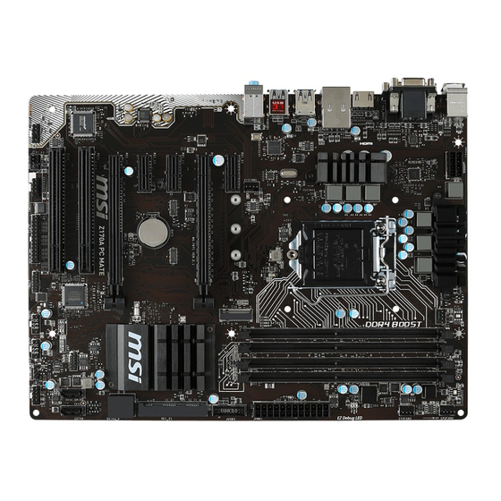
  • Seite 50: Übersicht Der Komponenten

    Übersicht der Komponenten DIMM4 CPUFAN1 SYSFAN1 DIMM3 JPWR2 CPU Sockel DIMM2 DIMM1 CPUFAN2 SYSFAN3 EZ Debug LED JPWR1 PCI_E1 JUSB3 M2_1 PCI_E2 PCI_E3 SE1_21 PCI_E4 JCI1 JBAT1 PCI_E5 SATA3_4 SATA5 PCI1 SATA6 PCI2 JFP1 JAUD1 JFP2 SYSFAN2 JUSB1 JCOM1 JUSB2 JTPM1 JLTP1 Übersicht der Komponenten...
  • Seite 51: Cpu Sockel

    ● ● Bitte bewahren Sie die CPU Schutzkappe nach der Installation des Prozessors auf. MSI wird RMA (Return Merchandise Authorization) Anfragen nur dann behandeln, wenn die Schutzklappe auf dem CPU-Sockel des Motherboards sitzt. ● Wenn Sie eine CPU einbauen, denken sie bitte daran, einen CPU-Kühler zu installieren.
  • Seite 52: Dimm-Steckplätze

    DIMM-Steckplätze DIMM1 DIMM3 Kanal A Kanal B DIMM2 DIMM4 Speichermodul-Installationsempfehlung DIMM4 DIMM4 DIMM3 DIMM2 DIMM2 DIMM2 DIMM1 Wichtig ● Um einen sicheren Systemstart zu gewährleisten, bestücken Sie immer DIMM2 zuerst. ● Aufgrund der Chipsatzressourcennutzung wird die verfügbare Kapazität des Speichers kleiner sein als die Größe der installierten Speicherkapazität. Basierend auf der Intel CPU Spezifikation wird eine Speicherspannung unter 1,35 ●...
  • Seite 53: Pci_E1~5, Pci1~2: Pcie/ Pci Erweiterungssteckplätze

    PCI_E1~5, PCI1~2: PCIe/ PCI Erweiterungssteckplätze PCI_E1: PCIe 3.0 x1-Steckplatz PCI_E2: PCIe 3.0 x16-Steckplatz PCI_E3: PCIe 3.0 x1-Steckplatz PCI_E4: PCIe 3.0 x1-Steckplatz PCI_E5: PCIe 3.0 x4-Steckplatz PCI1: PCI-Steckplatz PCI2: PCI-Steckplatz Tabelle der PCIe-Steckplätze-Bandbreiten Steckplatz Bandbreite PCI_E1 3.0 x1 3.0 x1 3.0 x1 ─...
  • Seite 54: Sata1~6: Sata 6Gb/S Anschlüsse

    SATA1~6: SATA 6Gb/s Anschlüsse Dieser Anschluss basiert auf der Hochgeschwindigkeitsschnittstelle SATA 6Gb/s. Pro Anschluss kann ein SATA Gerät angeschlossen werden. SATA1 SATA5 SATA2 SATA4 SATA3 SATA6 Wichtig ● Die SATA1~2 Anschlüsse werden nicht zur Verfügung stehen, wenn Sie ein M.2 SATA Schnittstellenmodul im M.2 Steckplatz installieren.
  • Seite 55: M2_1: M.2 Steckplatz

    M2_1: M.2 Steckplatz Wichtig Intel RST unterstützt nur PCIe M.2 SSD mit UEFI ROM, ® Legacy-ROM wird NICHT unterstützt. Video-Demonstration Eine anschauliche Darstellung zur Installation eines M.2 Moduls finden Sie im Video. http://youtu.be/JCTFABytrYA Installation eines M.2 Moduls Entfernen Sie die Scharube aus dem Schraubsockel.
  • Seite 56: Jfp1, Jfp2: Frontpanel-Anschlüsse

    M.2/ SATA & SATAe Kombinationstabelle Steckplatz Verfügbare SATA/ SATA Express Anschlüsse M2_1 Leer M.2 SATA M.2 PCIe SATA Express ✓ ✓ ✓ SATA1 ✓ ─ ✓ SATA2 ✓ ─ ✓ SATA3 ✓ ✓ ─ SATA4 ✓ ✓ ─ SATA5 ✓ ✓...
  • Seite 57: Jpwr1~2: Stromanschlüsse

    JPWR1~2: Stromanschlüsse Mit diesen Anschlüssen verbinden Sie die ATX Stromstecker. JPWR2 Ground +12V Ground +12V Ground +12V Ground +12V +3.3V +3.3V +3.3V -12V Ground Ground PS-ON# Ground Ground Ground JPWR1 Ground Ground PWR OK 5VSB +12V +12V +3.3V Ground Wichtig Stellen Sie sicher, dass alle Anschlüsse mit den richtigen Anschlüssen des Netzteils verbunden sind, um einen stabilen Betrieb der Hauptplatine sicherzustellen.
  • Seite 58: Jusb3: Usb 3.1 Gen1 Anschluss

    Bitte beachten Sie, dass Sie die mit VCC (Stromführende Leitung) und Ground ● (Erdleitung) bezeichneten Pins korrekt verbinden müssen, ansonsten kann es zu Schäden kommen. ● Um das iPad, iPhone und iPod über USB-Anschlüsse aufzuladen, installieren Sie bitte die MSI SUPER CHARGER Software. ® Übersicht der Komponenten...
  • Seite 59: Jaud1: Audioanschluss Des Frontpanels

    JAUD1: Audioanschluss des Frontpanels Dieser Anschluss ermöglicht den Anschluss von Audiobuchsen eines Frontpanels. MIC L Ground MIC R Head Phone R MIC Detection SENSE_SEND No Pin Head Phone L Head Phone Detection JTPM1: TPM Anschluss Dieser Anschluss wird für das TPM Modul (Trusted Platform Module) verwendet. Weitere Informationen über den Einsatz des optionalen TPM Modules entnehmen Sie bitte dem TPM Plattform Handbuch.
  • Seite 60: Cpufan1~2,Sysfan1~3: Stromanschlüsse Für Lüfter

    CPUFAN1~2,SYSFAN1~3: Stromanschlüsse für Lüfter Diese Anschlüsse können im PWM (Pulse Width Modulation) Modus oder Spannungsmodus betrieben werden. Im PWM-Modus bieten die Lüfteranschlüsse konstante 12V Ausgang und regeln die Lüftergeschwindigkeit per Drehzahlsteuersignal. Im Spannungsmodus bestimmen die Lüfteranschlüsse die Lüftergeschwindigkeit durch Ändern der Spannung. Wenn Sie ein 3-Pin (Non- PWM) Lüfter an einen PWM-Modus Lüfteranschluss anschließen, läuft der Lüfter mit höchster Drehzahl und kann unangenehm laut werden.
  • Seite 61: Jlpt1: Parallele Schnittstelle

    JLPT1: Parallele Schnittstelle Mit dieser Schnittstellekönnen Sie das optionale parallele Schnittstelle mit dem Einbausatze verbinden. RSTB# AFD# PRND0 ERR# PRND1 PINIT# PRND2 LPT_SLIN# PRND3 Ground PRND4 Ground PRND5 Ground PRND6 Ground PRND7 Ground ACK# Ground BUSY Ground Ground SLCT No Pin JBAT1: Steckbrücke zur CMOS-Löschung (Reset des BIOS) Der Onboard CMOS Speicher (RAM) wird durch eine externe Spannungsversorgung durch eine Batterie auf dem Motherboard versorgt, um die Daten der...
  • Seite 62: Jci1: Gehäusekontaktanschluss

    JCI1: Gehäusekontaktanschluss Dieser Anschluss wird mit einem Kontaktschalter verbunden. Normal Trigger Gehäusekontakt (Standardwert) Event Gehäusekontakt-Detektor verwenden Schließen Sie den JCI1-Anschluss am Gehäusekontakt-Schalter/ Sensor am Gehäuse an. Schließen Sie die Gehäuseabdeckung. Gehen Sie zu BIOS > Settings > Security > Chassis Intrusion Configuration. Stellen Sie Chassis Intrusion auf Aktiviert (Enabled).
  • Seite 63: Bios-Setup

    Press DEL key to enter Setup Menu, F11 to enter Boot Menu erscheint. ● Verwenden Sie die MSI FAST BOOT Anwendung. Klicken Sie die GO2BIOS-Taste und drücken OK. Das System startet neu und geht direkt ins BIOS. Klicken Sie auf GO2BIOS ●...
  • Seite 64: Reset Des Bios

    Aktualisierung des BIOS mit dem M-FLASH-Programm Vorbereitung: Laden Sie bitte die neueste BIOS Version, die dem Motherboard-Modell entspricht, von der offiziellen MSI Website herunter und speichern Sie die BIOS-Datei auf USB- Flash-Laufwerk. BIOS-Aktualisierungsschritte: Drücken Sie während des POST-Vorgangs die Taste (Entf), um das BIOS zu öffnen.
  • Seite 65: Ez Modus

    EZ Modus Im EZ-Modus können Sie die Grundinformationen des Systems einsehen und grundlegende Einstellungen konfigurieren. Um die erweiterten BIOS-Einstellungen anzeigen zu lassen, aktivieren Sie bitte den Erweiterten Modus durch Drücken des Setup Mode Schalter oder der Funktionstaste F7. XMP Schalter Setup Mode Schalter Screenshot Favoriten...
  • Seite 66 OC GENIE 4 Schalter - Klicken Sie den Umschalter der OC GENIE 4 Funktion, um ● den CPU mit MSI optimierte Einstellung automatisch zu übertakten. Wichtig Biite ändern Sie keine Werte im OC Menü und laden Sie keine Standardwerte während GAME GENIE 4 aktiviert ist, um die optimale Leistung und Stabilität des Systems zu gewährleisten.
  • Seite 67: Erweiterten Modus

    Erweiterten Modus Drücken Sie den Setup Mode Schalter oder die Funkionstaste F7, um zwischen den EZ-Modus und Erweiterten-Modus im BIOS-Setup zu wechseln. XMP Schalter Setup Modus Schalter Screenshot Favoriten Sprache System- information OC GENIE 4 Schalter Bootgeräte- Prioritätsleiste BIOS-Menü BIOS-Menü -Auswahl -Auswahl Menüanzeige...
  • Seite 68 In diesem Menü können Benutzer das BIOS anpassen und das Mainboard übertakten. Bitte führen Sie nur Änderungen durch, wenn Sie sich über das Ergebnis im Klaren sind. Sie sollten Erfahrung beim Übertakten haben, da Sie sonst das Motherboard oder Komponenten des Systems beschädigen können. Wichtig ●...
  • Seite 69 Ring Ratio [Auto] ▶ Setzen Sie den Ring Ratio. Der erlaubte Wertebereich ist abhängig von der installierten CPU. Adjusted Ring Frequency ▶ Zeigt die angepasste Ring Frequenz. Nur Anzeige – keine Änderung möglich.. ▶ GT Ratio [Auto] Setzen Sie den Multiplikator der integrierten Grafik. Der erlaubte Wertebereich ist abhängig von der installierten CPU.
  • Seite 70 Adjusted DRAM Frequency ▶ Zeigt die Speicherfrequenz an. Nur Anzeige – keine Änderung möglich. ▶ Extreme Memory Profile (X.M.P.) [Disabled] Extreme Memory Profiles (XMP) sind von Intel eingeführte Zertifizierungen für DDR3- Speichermodule aus dem PC-Bereich. Diese Option steht zur Verfügung, wenn die installierten Speichermodule die XMP Technik unterstützen.
  • Seite 71 Hyper-Threading [Enabled] ▶ Die Intel Hyper-Threading Technologie behandelt die Prozessorkerne innerhalb des Prozessors als multi-logische Prozessoren, die Anweisungen simultan durchführen können. Dadurch tritt eine wesentliche Verbesserung der Systemleistung ein. Diese Option wird angezeigt, wenn die installierte CPU diese Einstellungen unterstützt. [Enable] Aktiviert die Intel Hyper-Threading Technologie.
  • Seite 72 Adjacent Cache Line Prefetch [Enabled] ▶ Aktiviert oder deaktiviert den CPU Hardware Prefetcher (MLC Spatial prefetcher). [Enabled] Ermöglicht Adjacent Cache Line Prefetch zur Verringerung der Cache Latenzzeit und zur Leistungssteigerung von Applikationen. [Disabled] Aktiviert nur die angeforderten Cache-Zeilen. ▶ CPU AES Instructions [Enabled] Aktiviert oder deaktiviert die CPU AES (Advanced Encryption Standard-New Instructions) Unterstützung.
  • Seite 73 EIST [Enabled] ▶ Aktivieren oder deaktivieren Sie die Enhanced Intel SpeedStep Technologie. ® Diese Option wird angezeigt, wenn OC Explore Mode auf Normal eingestellt. [Enabled] Aktiviert EIST, um die CPU-Spannung und Taktfrequenz dynamisch anzupassen. Es kann zu verringern durchschnittliche Stromverbrauch und die durchschnittliche Wärmeproduktion. [Disabled] Deaktiviert EIST.
  • Seite 74: Softwarebeschreibung

    Installation von Treibern Starten Sie Ihren Computer mit Windows 7/ 8.1/ 10. ® Legen Sie die MSI Treiber Disk in das optisches Laufwerk. ® Der Installer wird automatisch erscheint und findet und finden Sie die benötigten Treiber in die Liste.
  • Seite 75 Table des matières Information de sécurité ..................2 Spécifications ......................3 Panneau arrière Entrée/ Sortie ................7 Tableau explicatif de l’état de la LED du port LAN ..........7 Configuration audio 7.1-canal ................7 Vue d’ensemble des composants ................8 Socket processeur ....................9 Slots DIMM ......................
  • Seite 76: Information De Sécurité

    Information de sécurité ● Les composants emballés risquent d’être endommagés par le décharge électrostatique (ESD). Veuillez référer aux instructions ci-dessous pour réussir à assembler l’ordinateur. ● Assurer de bien connecter tous les composants. L’ordinateur peut échouer à reconnaître un composant ou ne peut se démarrer à cause d’une connexion mal fixée.
  • Seite 77: Spécifications

    Spécifications Support des processeurs Intel Core i3/i5/i7, Intel ® ™ ® Pentium et Celeron de 6ème génération pour Socket ® ® LGA1151 Chipset Chipset Intel Z170 Express ® ● 4 x slots pour mémoire DDR4, support jusqu’à 64 Go ▶ Support DDR4 3200(OC)/ 3000(OC)/ 2800(OC)/ 2600(OC)/ 2400/ 2133 MHz Mémoire...
  • Seite 78 Continué de la page précédente ● Chipset ASMedia ASM1142 ® ▶ 2 x ports USB 3.1 Gen2 (SuperSpeed USB 10Gbps) sur le panneau arrière ● Chipset Intel Z170 Express ® ▶ 6 x ports USB 3.1 Gen1 (SuperSpeed USB) (4 ports sur le panneau arrière, 2 ports disponibles par l’intermédiaire du connecteur USB 3.1 Gen1 interne) ▶...
  • Seite 79 Continué de la page précédente ● 1 x connecteur d’alimentation principal ATX 24 broches ● 1 x connecteur d’alimentation ATX 12V 8 broches ● 6 x connecteurs SATA 6 Gb/s ● 1 x connecteur SATA Express ● 2 x connecteurs USB 2.0 (support de 4 autres ports USB 2.0) ●...
  • Seite 80 Continué de la page précédente ● Pilotes ● COMMAND CENTER ● LIVE UPDATE 6 ● FAST BOOT ● SUPER CHARGER Logiciel ● M-CLOUD ● RAMDISK ● NETWORK GENIE ● Intel Extreme Tuning Utility ® ● Norton™ Security ● Google Chrome™ ,Google Toolbar et Google Drive ●...
  • Seite 81: Panneau Arrière Entrée/ Sortie

    Panneau arrière Entrée/ Sortie Ligne-in Souris PS/2 Port VGA Ligne-out Mic-in Clavier PS/2 USB 3.1 Gen2 Port DVI-D USB 3.1 Gen1 Tableau explicatif de l’état de la LED du port LAN LED indiquant la connexion LED indiquant la vitesse et l’activité Etat Description Etat...
  • Seite 82: Vue D'ensemble Des Composants

    Vue d’ensemble des composants DIMM4 CPUFAN1 SYSFAN1 DIMM3 Socket processeur JPWR2 DIMM2 DIMM1 CPUFAN2 SYSFAN3 EZ Debug LED JPWR1 PCI_E1 JUSB3 M2_1 PCI_E2 PCI_E3 SE1_21 PCI_E4 JCI1 JBAT1 PCI_E5 SATA3_4 SATA5 PCI1 SATA6 PCI2 JFP1 JAUD1 JFP2 SYSFAN2 JUSB1 JCOM1 JUSB2 JTPM1 JLTP1...
  • Seite 83: Socket Processeur

    ● Veuillez garder le capot de protection du processeur après l’installation du processeur. Selon les exigences de RMA (Return Merchandise Authorization), MSI n’acceptera pas les cartes mère dont le capot de protection aura été retiré. Lors de l’installation d’un processeur, n’oubliez pas d’installer un ventilateur ●...
  • Seite 84: Slots Dimm

    Slots DIMM DIMM1 DIMM3 Canal A Canal B DIMM2 DIMM4 Installation recommandée de module mémoire DIMM4 DIMM4 DIMM3 DIMM2 DIMM2 DIMM2 DIMM1 Important ● Veillez à toujours insérer un module de mémoire dans l’emplacement DIMM2 en premier. ● Du fait des ressources utilisées par le chipset, la capacité de mémoire disponible est un peu moins élevée que celle installée.
  • Seite 85: Pci_E1~5, Pci1~2 : Slots D'extension Pcie Et Pci

    PCI_E1~5, PCI1~2 : Slots d’extension PCIe et PCI PCI_E1 : slot PCIe 3.0 x1 PCI_E2 : slot PCIe 3.0 x16 PCI_E3 : slot PCIe 3.0 x1 PCI_E4 : slot PCIe 3.0 x1 PCI_E5 : slot PCIe 3.0 x4 PCI1 : slot PCI PCI2 : slot PCI Tableau du débit de slots PCIe Slot...
  • Seite 86: Sata1~6 : Connecteurs Sata 6Gb/S

    SATA1~6 : Connecteurs SATA 6Gb/s Ce connecteur est un port à interface SATA 6 Gb/s. Chaque connecteur peut être relié à un appareil SATA. SATA1 SATA5 SATA2 SATA4 SATA3 SATA6 Important ● Les ports SATA1~2 sont indisponible pendant l’installation du module d’interface M.2 SATA dans le slot M.2.
  • Seite 87: M2_1 : Slots M.2

    M2_1 : Slots M.2 Important La technologie Intel RST supporte seulement un SSD ® M.2 PCIe avec une mémoire ROM UEFI et non avec une mémoire ROM Legacy. Vidéo de démonstration Pour en savoir plus sur l’installation du module M.2, cliquez sur le lien ci-dessous. http://youtu.be/JCTFABytrYA Installation du module M.2 Enlevez la vis de la vis...
  • Seite 88: Jfp1, Jfp2 : Connecteurs Panneau Avant

    Tableau de combinaison M.2/ SATA & SATAe Slot Connecteurs SATA/ SATAe disponibles M2_1 Vide M.2 SATA M.2 PCIe SATA Express ✓ ✓ ✓ SATA1 ✓ ─ ✓ SATA2 ✓ ─ ✓ SATA3 ✓ ✓ ─ SATA4 ✓ ✓ ─ SATA5 ✓...
  • Seite 89: Jpwr1~2 : Connecteurs D'alimentation

    JPWR1~2 : Connecteurs d’alimentation Ce connecteur vous permet de relier une alimentation ATX. JPWR2 Ground +12V Ground +12V Ground +12V Ground +12V +3.3V +3.3V +3.3V -12V Ground Ground PS-ON# Ground Ground Ground JPWR1 Ground Ground PWR OK 5VSB +12V +12V +3.3V Ground Important...
  • Seite 90: Jusb3 : Connecteur Usb 3.1 Gen1

    Notez que les broches VCC et Terre doivent être branchées correctement afin ● d’éviter tout dommage sur la carte mère. Pour recharger votre tablette, smartphone ou autre périphérique par l’intermédiaire ● d’un port USB, veuillez installer l’utilitaire MSI SUPER CHARGER. ® Vue d’ensemble des composants...
  • Seite 91: Jaud1 : Connecteur Audio Avant

    JAUD1 : Connecteur audio avant Ce connecteur se lie aux jacks audio du panneau avant. MIC L Ground MIC R Head Phone R MIC Detection SENSE_SEND No Pin Head Phone L Head Phone Detection JTPM1 : Connecteur de module TPM Ce connecteur est relié...
  • Seite 92: Cpufan1~2,Sysfan1~3 : Connecteurs Pour Ventilateurs

    CPUFAN1~2,SYSFAN1~3 : Connecteurs pour ventilateurs Les connecteurs pour ventilateurs peuvent être utilisés en mode PWM (Pulse Width Modulation) et en mode tension. En mode PWM, les connecteurs fournissent une sortie de 12V constante et ajustent la vitesse des ventilateurs avec un signal de contrôle de vitesse.
  • Seite 93: Jlpt1 : Connecteur De Port Parallèle

    JLPT1 : Connecteur de port parallèle Ce connecteur sert à connecter un support de port parallèle optionnel. RSTB# AFD# PRND0 ERR# PRND1 PINIT# PRND2 LPT_SLIN# PRND3 Ground PRND4 Ground PRND5 Ground PRND6 Ground PRND7 Ground ACK# Ground BUSY Ground Ground SLCT No Pin JBAT1 : Cavalier clear CMOS (Réinitialisation BIOS)
  • Seite 94: Jci1 : Connecteur Intrusion Châssis

    JCI1 : Connecteur intrusion châssis Ce connecteur est relié à un câble d’interrupteur intrusion châssis. Normal Commencer l’activité intrusion châssis (défaut) Utilisation du détecteur d’intrusion châssis Reliez le connecteur JCI1 à l’interrupteur ou au capteur d’intrusion châssis situé sur le boîtier du PC. Fermez le couvercle du boîtier.
  • Seite 95: Configuration Du Bios

    Menu, F11 to enter Boot Menu” sur l’écran, veuillez appuyer sur la touche Suppr. ● Quand l’ordinateur est déjà en marche, vous pouvez utiliser l’application MSI FAST BOOT. Cliquez sur le bouton GO2BIOS puis sur OK. Le système redémarre et entre dans l’interface Setup du BIOS.
  • Seite 96: Réinitialiser Le Bios

    Avant la mise à jour : Veuillez télécharger la dernière version de BIOS compatible à votre carte mère sur le site MSI. Ensuite, veuillez sauvegarder le nouveau BIOS sur le lecteur flash USB. Mettre le BIOS à jour : Appuyez sur la touche Suppr pour entrer dans l’interface Setup du BIOS pendant le processus de POST.
  • Seite 97: Ez Mode (Mode Simplifié)

    EZ Mode (mode simplifié) Le mode EZ vous fournit les informations basiques du système et vous permet de configurer les réglages de base. Si vous souhaitez configurer les réglages du BIOS, veuillez utiliser le mode Advanced en appuyant sur le switch Setup Mode ou la touche de fonction F7.
  • Seite 98 ● OC GENIE 4 toggle - cliquez sur ce bouton pour démarrer la fonction OC GENIE 4 et ainsi overclocker le CPU avec les réglages optimisés par MSI. Important Après l’activation de la fonction OC GENIE 4 , il est conseillé de ne faire aucune modification dans menu OC et de ne pas charger les réglages par défauts pour...
  • Seite 99: Advanced Mode (Mode Avancé)

    Advanced mode (mode avancé) Appuyez sur le Setup Mode switch (interrupteur de modes de réglages) ou sur la touche de fonction F7 pour commuter entre le mode simplifié et le mode avancé. XMP switch Setup Mode switch Screenshot Favorites Language System information OC GENIE 4...
  • Seite 100 Ce menu est destiné aux utilisateurs avancés souhaitant overclocker leur carte mère. Important ● L’overclocking manuel du PC n’est recommandé que pour les utilisateurs avancés. L’overclocking n’est pas garanti et une mauvaise manipulation peut rendre nulle ● votre garantie et sévèrement endommager votre matériel. ●...
  • Seite 101 GT Ratio [Auto] ▶ Règle le ratio de la puce graphique intégrée. La gamme de valeur valides dépend du processeur installé. Adjusted GT Frequency ▶ Montre la fréquence de la puce graphique intégrée modifiée. Fonctionne uniquement en lecture seule. Misc Setting* ▶...
  • Seite 102 Extreme Memory Profile (X.M.P.) [Disabled] ▶ La technologie d’overclocking X.M.P. (Extreme Memory Profile) permet un overclocking par l’intermédiaire du module de mémoire. Ce menu est seulement disponible si vous disposez de modules de mémoire prenant en charge la technologie XMP. [Disabled] Désactive cette fonction.
  • Seite 103 CPU Features ▶ Appuyez sur la touche [Entrée] pour accéder au sous-menu. ▶ Hyper-Threading [Enabled] La technologie d’hyper-threading traite chaque cœur processeur comme un processeur logique indépendant doté de ses propres données et permet de les faire fonctionner de manière simultanée. Ainsi, les performances système sont grandement améliorées.
  • Seite 104 Adjacent Cache Line Prefetch [Enabled] ▶ Active ou désactive le prefetcher matériel du processeur (MLC Spatial prefetcher). [Enabled] Active le prefetcher de la ligne de cache adjacente pour réduire le temps de latence et ajuster les performances dans l'application spécifique. [Disabled] Active seulement la ligne de cache exigée.
  • Seite 105 EIST [Enabled] ▶ Active ou désactive Enhanced Intel SpeedStep Technology. Ce menu apparaît ® lorsque OC Explore Mode est mis en Normal. [Enabled] Active la technologie EIST pour ajuster la tension du processeur et de la fréquence du cœur de manière dynamique. Cela diminue la consommation d’énergie et la production de chaleur moyennes.
  • Seite 106: Informations Sur Les Logiciels

    ® Installer les pilotes Allumez l’ordinateur sous Windows 7/ 8.1/ 10. ® Insérez le disque MSI Driver Disc dans le lecteur optique. ® L’outil d’installation apparaît automatiquement. Il trouvera et listera tous les pilotes dont vous avez besoin. Cliquez sur le bouton Install.
  • Seite 107 Содержание Безопасное использование продукции ............2 Технические характеристики ................3 Задняя панель ввода/ вывода ................7 Таблица состояния индикатора порта LAN ............. 7 Компоненты материнской платы ..............8 Процессорный сокет ..................9 Слоты DIMM ..................... 10 PCI_E1~5, PCI1~2: Слоты расширения PCIe/ PCI ......... 11 SATA1~6: Разъемы...
  • Seite 108: Безопасное Использование Продукции

    Безопасное использование продукции ● Компоненты, входящие в комплект поставки могут быть повреждены статическим электричеством. Для успешной сборки компьютера, пожалуйста, следуйте указаниям ниже. ● Убедитесь, что все компоненты компьютера подключены должным образом. Ослабленные соединения компонентов могут привести как к сбоям в работе, так...
  • Seite 109: Технические Характеристики

    Технические характеристики Поддержка процессоров Intel Core i3/i5/i7, Intel ® ™ ® Процессор Pentium и Celeron 6-го поколения для сокета LGA1151 ® ® Чипсет Intel Z170 Express ® ● 4x DDR4 слота памяти с поддержкой до 64 ГБ ▶ Поддержка DDR4 3200(OC)/ 3000(OC)/ 2800(OC)/ 2600(OC)/ 2400/ 2133 МГц...
  • Seite 110 Продолжение с предыдущей страницы ● Чипсет ASMedia ASM1142 ® ▶ 2x порта USB 3.1 Gen2 (SuperSpeed USB 10 Гбит) на задней панели ● Чипсет Intel Z170 Express ® ▶ 6x портов USB 3.1 Gen1 (SuperSpeed USB) (4 порта на задней панели, 2 порта доступны через внутренние...
  • Seite 111 Google Chrome™, Google Toolbar, Google Drive ● CLICK BIOS 5 ▶ Режим EZ и расширенный режим ▶ Board Explorer ▶ Аппаратный мониторинг ● COMMAND CENTER MSI Эксклюзивные ▶ Мониторинг системы функции ▶ Интеллектуальное управление скоростью вращения вентиляторов ● RAMDISK ● LIVE UPDATE 6 ●...
  • Seite 112 Продолжение с предыдущей страницы ● Поддержка DDR4 Boost ▶ Поддержка двухканальной памяти DDR4 ▶ Изолированные электрические цепи DDR4 ▶ DDR4 XMP Ready ● Поддержка PCI Express 3.0 Мелирование характеристики ▶ Поддержка 2-Way AMD CrossFire ● USB 3.1 Gen2 Ready ▶ USB 3.1 Gen2 (10 Гб/с) Type-A Ready ●...
  • Seite 113: Задняя Панель Ввода/ Вывода

    Задняя панель ввода/ вывода Линейный вход PS/2 мышь Порт VGA Линейный выход Микрофон- вход PS/2 клавиатура USB 3.1 Gen2 Порт DVI-D USB 3.1 Gen1 Таблица состояния индикатора порта LAN Подключение/ Работа Скорость передачи данных индикатора Состояние Описание Состояние Описание Выкл. 10 Мбит/с...
  • Seite 114: Компоненты Материнской Платы

    Компоненты материнской платы DIMM4 CPUFAN1 SYSFAN1 DIMM3 Процессорный JPWR2 DIMM2 сокет DIMM1 CPUFAN2 SYSFAN3 EZ Debug LED JPWR1 PCI_E1 JUSB3 M2_1 PCI_E2 PCI_E3 SE1_21 PCI_E4 JCI1 JBAT1 PCI_E5 SATA3_4 SATA5 PCI1 SATA6 PCI2 JFP1 JAUD1 JFP2 SYSFAN2 JUSB1 JCOM1 JUSB2 JTPM1 JLTP1 Компоненты...
  • Seite 115: Процессорный Сокет

    отключить кабель питания. ● Пожалуйста, сохраните защитную крышку процессорного сокета после установки процессора. Любые возможные гарантийные случаи, связанные с работой материнской платы, MSI будет рассматривать только, при наличии защитной крышки на процессорном сокете. ● При установке процессора обязательно установите процессорный...
  • Seite 116: Слоты Dimm

    Слоты DIMM DIMM1 DIMM3 Канал A Канал B DIMM2 DIMM4 Рекомендации по установке модулей памяти DIMM4 DIMM4 DIMM3 DIMM2 DIMM2 DIMM2 DIMM1 Внимание! ● Всегда устанавливайте модуль памяти сначала в слот DIMM2. ● В связи со спецификой использования ресурсов чипсета, доступный объем памяти...
  • Seite 117: Pci_E1~5, Pci1~2: Слоты Расширения Pcie/ Pci

    PCI_E1~5, PCI1~2: Слоты расширения PCIe/ PCI PCI_E1: PCIe 3.0 x1 слот PCI_E2: PCIe 3.0 x16 слот PCI_E3: PCIe 3.0 x1 слот PCI_E4: PCIe 3.0 x1 слот PCI_E5: PCIe 3.0 x4 слот PCI1: PCI слот PCI2: PCI слот Таблица пропускной способности Слотов PCIe Слот...
  • Seite 118: Sata1~6: Разъемы Sata 6 Гб/С

    SATA1~6: Разъемы SATA 6 Гб/с Эти разъемы представляют собой интерфейсные порты SATA 6 Гб/с. К каждому порту можно подключить одно устройство SATA. SATA1 SATA5 SATA2 SATA4 SATA3 SATA6 Внимание! ● Порты SATA1~2 будут недоступны при установке модуля M.2 SATA в разъем M.2.
  • Seite 119: Установка Модуля

    M2_1: Разъем M.2 Внимание! Intel RST поддерживает только PCIe M.2 SSD с UEFI ® option ROM, и не поддерживает Legacy option ROM. Видео Инструкция Смотрите видео, чтобы узнать как установить модуль M.2. http://youtu.be/JCTFABytrYA Установка модуля M.2 Выкрутите винт из базового винта. Выкрутите...
  • Seite 120: Jfp1, Jfp2: Разъемы Передней Панели

    Таблица комбинации M.2/ SATA и SATAe Слот Доступные разъемы SATA/ SATA Express M2_1 Пусто M.2 SATA M.2 PCIe SATA Express ✓ ✓ ✓ SATA1 ✓ ─ ✓ SATA2 ✓ ─ ✓ SATA3 ✓ ✓ ─ SATA4 ✓ ✓ ─ SATA5 ✓...
  • Seite 121: Jpwr1~2: Разъемы Питания

    JPWR1~2: Разъемы питания Данные разъемы предназначены для подключения коннекторов питания ATX. JPWR2 Ground +12V Ground +12V Ground +12V Ground +12V +3.3V +3.3V +3.3V -12V Ground Ground PS-ON# Ground Ground Ground JPWR1 Ground Ground PWR OK 5VSB +12V +12V +3.3V Ground Внимание! Для...
  • Seite 122: Jusb3: Разъем Usb 3.1 Gen1

    Ground Ground No Pin Внимание! ● Помните, что во избежание повреждений необходимо правильно подключать контакты VCC и Ground. ● Для того, чтобы зарядить ваш iPad, iPhone и iPod портами USB, пожалуйста, установите утилиту MSI SUPER CHARGER. ® Компоненты материнской платы...
  • Seite 123: Jaud1: Разъем Аудио Передней Панели

    JAUD1: Разъем аудио передней панели Данный разъем предназначен для подключения аудиоразъемов передней панели. MIC L Ground MIC R Head Phone R MIC Detection SENSE_SEND No Pin Head Phone L Head Phone Detection JTPM1: Разъем модуля ТРМ Данный разъем испльзуется для подключения модуля ТРМ (Trusted Platform Module).
  • Seite 124: Cpufan1~2,Sysfan1~3: Разъемы Вентиляторов

    CPUFAN1~2,SYSFAN1~3: Разъемы вентиляторов Разъемы вентиляторов можно разделить на два типа: с PWM (PulseWidth Modulation) управлением и управлением постоянным током. Разъемы вентиляторов с PWM управлением имею контакт с постоянным напряжением 12В, а также контакт с сигналом управления скоростью вращения. Управление скоростью вращения вентиляторов с управлением постоянным током, осуществляется...
  • Seite 125: Jlpt1: Разъем Параллельного Порта

    JLPT1: Разъем параллельного порта Этот разъем позволяет подключить параллельный порт, размещенный на внешнем брекете. RSTB# AFD# PRND0 ERR# PRND1 PINIT# PRND2 LPT_SLIN# PRND3 Ground PRND4 Ground PRND5 Ground PRND6 Ground PRND7 Ground ACK# Ground BUSY Ground Ground SLCT No Pin JBAT1: Джампер...
  • Seite 126: Jci1: Разъем Датчика Открытия Корпуса

    JCI1: Разъем датчика открытия корпуса К этому разъему подключается кабель от датчика открытия корпуса. Нормально Разрешить запись по событию открытия (По умолчанию) корпуса Использование датчика открытия корпуса Подключите подключите датчик открытия корпуса к разъему JCI1. Закройте крышку корпуса. Войдите в BIOS > Settings > Security > Chassis Intrusion Configuration. Установите...
  • Seite 127: Настройка Bios

    Нажмите клавишу Delete, когда появляется сообщение на экране Press DEL key to enter Setup Menu, F11 to enter Boot Menu во время загрузки. ● При помощи приложения MSI FAST BOOT. Нажмите на кнопку GO2BIOS и выберите ОК. Система перезагрузится и автоматически войдет в настройки BIOS.
  • Seite 128: Сброс Bios

    разделу джампера/ кнопки очистки данных CMOS. Обновление BIOS Обновление BIOS при помощи M-FLASH Подготовительные операции: Пожалуйста, скачайте последнюю версию файла BIOS с сайта MSI, который соответствует вашей модели материнской платы. Сохраните файл BIOS в флэш- диске USB. Обновление BIOS: Нажмите клавишу Del для входа в настройки BIOS во время процедуры...
  • Seite 129: Режим Ez

    Режим EZ Режим EZ представляет основную информацию о системем и позволяет выполнить основные операции по настройке. Для настройки расширенных функций BIOS, пожалуйста, войдите в Расширенный режим, путем нажатия Переключатель режимов установки или функциональной клавиши F7. Переключатель режимов установки Переключатель XMP Скриншот...
  • Seite 130 только в случае, если установлен модуль памяти с подержкой X.M.P. Переключатель OC GENIE 4 - нажмите, чтобы переключить функцию ● OC GENIE 4, который может автоматически разгонять процессор с MSI оптимизированной настройкой. Внимание! Для сохранения оптимальной производительность и стабильности системы...
  • Seite 131: Режим Разгона

    Режим разгона Нажмите переключатель режимов установки или функциональную клавишу F7 для переключения между режимами EZ и разгона в настройки BIOS. Переключатель режимов установки Переключатель XMP Скриншот Избранное Язык Информация о системе Переключатель OC GENIE 4 Приоритет загрузочных устройств Выбор меню Выбор...
  • Seite 132 Данное меню предназначено для опытных пользователей и предоставляет возможности для «разгона» системы. Внимание! ● Разгонять ПК вручную рекомендуется только опытным пользователям. ● Производитель не гарантирует успешность разгона. Неправильное выполнение разгона может привести к аннулированию гарантии и серьезному повреждению оборудования. ● Неопытным...
  • Seite 133 GT Ratio [Auto] ▶ Установка множителя для интегрированной графики. Диапазон допустимых значений зависит от установленного процессора. Adjusted GT Frequency ▶ Показывает измененную частоту интегрированной графики. Это значение нельзя изменять. Misc Setting* ▶ Нажмите клавишу Enter, + или -, чтобы включить или выключить следующие 3 пункта, связанные...
  • Seite 134 Extreme Memory Profile (X.M.P.) [Disabled] ▶ X.M.P. (Extreme Memory Profile) является технологией разгона для модулей памяти. Этот пункт доступен при установке модулей памяти с поддержкой X.M.P. [Disabled] Функция выключена. [Profile 1] Использует настройки Профиль 1 для модуля памяти XMP. [Profile 2] Использует...
  • Seite 135 Hyper-Threading [Enabled] ▶ Технология Intel Hyper-Threading позволяет наскольким наборам регистров в процессоре исполнять инструкции одновременно. Это существенно увеличивает производительность системы. Этот пункт появляется, когда установленный процессор поддерживает изменение данного параметра. [Enable] Включить технологию Intel Hyper-Threading. [Disabled] Выключить эту функцию, если система не поддерживает функцию...
  • Seite 136 Adjacent Cache Line Prefetch [Enabled] ▶ Включение или выключение предвыборки процессора (MLC Spatial prefetcher). [Enabled] Включение соседней предвыборки линии кэша для сокращения времени задержки кэша и настройки производительности для определенного приложения. [Disabled] Включает только запрашиваемую линию кэша. ▶ CPU AES Instructions [Enabled] Включение...
  • Seite 137 Intel Turbo Boost [Enabled] ▶ Включение или выключение Intel Turbo Boost. Данный пункт применим для ® режима Simple и доступен, когда установленный процессор поддерживает данную функцию. [Enabled] Включение этой функции приводит к автоматическому увеличению производительности процессора. [Disabled] Функция выключена. Long Duration Power Limit (W) [Auto] ▶...
  • Seite 138: Описание Программного Обеспечения

    7/ 8.1/ 10. ® Установка драйверов Загрузите компьютер в Windows 7/ 8.1/ 10. ® Вставьте диск с драйверами MSI Driver Disc в привод для оптических ® дисков. Автоматически отобразится окно установщика, который найдет и перечислит все необходимые драйверы. Нажмите кнопку Install.
  • Seite 139: Regulatory Notices

    EU REACH Regulation (Regulation EC No. 1907/2006 of the European Parliament and the This device complies with part 15 of the FCC Rules. Council), MSI provides the information of chemical Operation is subject to the following two conditions: substances in products at: (1) This device may not cause harmful interference, http://www.msi.com/html/popup/csr/evmtprtt_pcm.html...
  • Seite 140 MSI will comply with the product take entregar a una empresa autorizada para la recogida de back requirements at the end of life of MSI-branded estos residuos.
  • Seite 141: Environmental Policy

    MSI si adeguerà a tale Direttiva ritirando tutti i prodotti marchiati MSI che sono stati venduti all’interno dell’Unione Europea alla fine del loro ciclo di vita.
  • Seite 142: Revision History

    Alternatively, please try the following help resources for further guidance. ● Visit the MSI website for technical guide, BIOS updates, driver updates, and other information: http://www.msi.com ● Register your product at: http://register.msi.com...

Diese Anleitung auch für:

3580129

Inhaltsverzeichnis