HELIX SDMI25 Bedienungsanleitung
Smart digital most interface
Inhaltsverzeichnis
Verfügbare Sprachen
Verfügbare Sprachen
Quicklinks
Inhaltsverzeichnis

Inhaltszusammenfassung für HELIX SDMI25
- Seite 1 SDMI 25 Smart Digital MOST Interface...
- Seite 2 Sehr geehrter Kunde, Wir gratulieren Ihnen zum Kauf dieses hochwertigen MOST-Adapters. Der SDMI25 ist ein MOST-Bus Interface, welcher das Audiosignal innerhalb des MOST Datenstroms ausliest und als optisch-digitales Stereosignal ausgibt. Zur Weiterverarbeitung des Stereosignals ist ein DSP (digitaler Signalprozessor) oder DSP-Verstärker mit optischem Digitaleingang erforderlich.
-
Seite 3: Allgemeine Hinweise
Einbaus und Anschlusses des Gerätes Voraussetzung für die Garan- tieleistungen sind. Der SDMI25 darf nur in Kraftfahrzeuge eingebaut werden, die den 12 V-Minuspol an Masse haben. Bei anderen Systemen können der MOST-Adapter und die elektrische Anlage des Kfz beschädigt werden. -
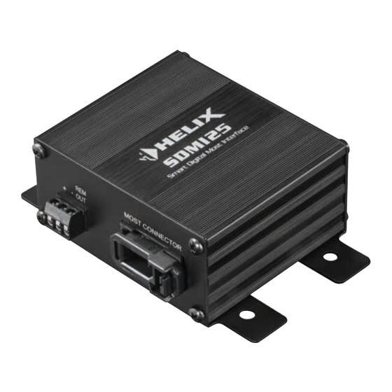
Seite 4: Anschluss- Und Bedienelemente
Zum Anschluss an die Bordnetzspannung mit einem zusätzlichen Remote-Ausgang. Der Remote-Ausgang muss zum Ein- und Ausschalten weiterer Komponenten angeschlossen werden. MOST Connector Zum Anschluss der MOST Lichtleiterverbindung des Fahrzeugs. Optical Out Optischer, digitaler Stereo-Signalausgang im SPDIF-Format. Jumper Zur fahrzeugspezifischen Konfiguration des SDMI25. - Seite 5 Inbetriebnahme und Funktionen 1 Power Input Diese Buchse dient zum Anschluss des SDMI25 an die Stromversor- gung des Fahrzeuges sowie für den Remote-Ausgang. +: Anschluss für das +12 V Versorgungskabel. Das Kabel ist am Pluspol der Spannungsquelle anzuschließen. Die Plusleitung sollte in einem Ab- stand von max.
-
Seite 6: Technische Daten
Informationen und Mehrkanal-Surroundsound-Formate wie Dolby oder DTS werden nicht unterstützt! 4 Jumper Mit Hilfe der Jumper muss der SDMI25 für den Einsatz im gewünschten Fahrzeug konfiguriert werden. Dazu Stecken Sie die Jumper einfach auf die entsprechenden Positionen. Eine Übersicht der Jumper-Konfigurati- onen finden Sie in der Übersicht auf Seite 7. -
Seite 7: Übersicht Jumper-Konfigurationen
Übersicht Jumper-Konfigurationen Hersteller Info Jumper Hersteller Info Jumper Seriennummer-Kopiervorgang Lamborghini mit OEM-Verstärker Audi MMI 2G, MMI 3G Mercedes NTG1 ohne AGW, NTG2 MMI 3G+ NTG2.5, NTG4, NTG4.5 MMI 3G+ NTG1 mit externer AGW E-, F-, G-Serie NTG3, NTG3.5 mit AGW (Becker) System-Signalton- Porsche bis 2008 PCM2.0,... -
Seite 8: Einbau Und Installation
Einbau und Installation Standard Anwendungsfall. Der SDMI25 ersetzt den OEM-Verstärker OEM-Modul IN OUT Autoradio OEM-Modul SPDIF SDMI25 OEM-Verstärker... - Seite 9 Standardmäßig wird der SDMI25 wie nachfolgend beschrieben an den MOST-Bus angeschlossen. Achtung: Bei einigen Fahrzeugtypen muss der Einbau nach einem ge- sonderten Ablauf erfolgen. Informationen dazu finden Sie auf Seite 11. 1. SDMI25 Jumper auf gewünschtes Fahrzeug einstellen (siehe Seite 7).
- Seite 10 (Abb. 4.2). IN & OUT des Signals muss zwingend beachtet werden. Siehe hierzu Abbildung 4.1. Achtung: Vor der ersten Installation muss der Schutz der Photodio- de im MOST-Connector des SDMI25 entfernt werden (Siehe rote Markierung in Abbildung 4.1). Entfernen Abb. 4.1 Abb.
-
Seite 11: Besondere Einbauhinweise
OEM-Verstärker Bevor Sie den OEM-Verstärker ausbauen, muss zuerst dessen Serien- nummer in den SDMI25 kopiert werden. Dazu gehen Sie wie folgt vor: 1. Alle drei Jumper vom SDMI25 entfernen (siehe Seite 4, Punkt 4). 2. SDMI25, bei ausgeschaltetem System, in den MOST-Bus einbauen (siehe Seite 10, Punkt 4, 5 und 7). - Seite 12 Besondere Einbauhinweise 3. System einschalten. Während des Systemstarts wird die Seriennum- mer des OEM-Verstärkers automatisch in den Speicher des SDMI25 kopiert. 4. Signalquelle wechseln. Wird kein Audiosignal mehr wiedergegeben, wurde die Seriennummer erfolgreich in den SDMI25 kopiert. 5. System ausschalten. Das Y-Lichtleiterkabel und den OEM-Verstär- ker aus dem MOST-Bus ausbauen.
- Seite 24 Audiotec Fischer GmbH Hünegräben 26 · 57392 Schmallenberg · Germany Tel.: +49 2972 9788 0 · Fax: +49 2972 9788 88 E-mail: helix@audiotec-fischer.com · Internet: www.audiotec-fischer.com...