Werbung
Quicklinks
Montage- und Anschlussanleitung / Sicherheitsrelaisbaustein
Mounting and wiring instructions / Safety relay module
Technische Daten
CE-Konformität
Bemessungsbetriebsspannung
Absicherung
der Betriebsspannung
Leistungsaufnahme
Schaltvermögen
der Freigabekontakte
Absicherung
der Freigabekontakte
Schaltvermögen
der Hilfskontakte
Absicherung der Hilfskontakte
Gebrauchskategorien
Anzugsverzögerung
Abfallverzögerung
Kontaktwerkstoff/Kontakte
Kontaktwiderstand
Luft- und Kriechstrecken
Schutzart
Kabelanschlüsse
Anzugsdrehmoment
Anschlussklemmen
Max. Gesamtleitungswiderstand 40 Ohm
Maße (H/B/T)
Gewicht
Betriebsumgebungstemperatur –25 °C ... +45 °C
Mechanische Lebensdauer
Anschlussbezeichnung
EMV
Schwingungen
gemäß Richtlinie 98/37/EC
24 VDC –15%/+10%,
Restwelligkeit max. 10%
interne elektronische Sicherung:
Auslösestrom > 0,2 A;
F3: Auslösestrom 0,6 A
max. 1,2 W
250 VAC, 6 A ohmsch (induktiv bei
geeigneter Schutzbeschaltung);
AC-15: 250 VAC/6 A, DC-13: 24 VDC/6 A
6 A träge
24 VDC, 2 A
2 A träge
AC-15/DC-13: EN IEC 60947-5-1
≤ 50 ms
≤ 30 ms
AgSnO, selbstreinigend, zwangsgeführt
max. 100 mOhm im Neuzustand
EN IEC 60 664-1 (DIN VDE 0110-1), 4 kV/2
Gehäuse: IP 40, Klemmen: IP 20,
Einbauraum: IP 54
Einzelleiter: starr oder flexibel (mit oder
ohne Aderendhülse) 0,25 ... 1,5 mm
Zweileiter mit gleichem Querschnitt:
• Steck- oder Printklemme: starr oder
flexibel (mit Aderendhülse ohne Kunst-
stoff) 0,25 ... 1,5 mm
, flexibel (ohne
2
oder mit TWIN-Aderendhülse)
0,5 ... 1,5 mm
,
2
• Federkraftklemme (z. B. Spring-Cage):
flexibel mit TWIN-Aderendhülse
0,5 ... 1,0 mm
2
0,6 Nm
100/22,5/121 mm
200 g
10
Schaltspiele
7
DIN EN 50 005/DIN 50 013
EN IEC 61 000-6-2, EN IEC 60 947-5-1
EN IEC 60 068-2-6, Frequenz:
10–55 Hz, Amplitude: 0,35 mm
Zweikanalige Ansteuerung, mit zwei
Tastern A und B
Leistungsebene: Zweikanalige
Ansteuerung, geeignet zur Kontakt-
verstärkung bzw. Kontaktverviel-
fältigung durch Schütze oder Relais
mit zwangsgeführten Kontakten.
Die Ansteuerung erkennt Draht-
brüche, Querschlüsse und Erd-
schlüsse im Überwachungskreis.
H2 = Rückführkreis
Wichtige Information:
Der Öffner der Taster A und B
muss geöffnet haben, bevor der
Schließerkontakt schließt. Keine
überlappenden Kontakte, da sonst
die Sicherungen F1 und F2 aus-
lösen würden!
Technical data
Conformity
Operating voltage
Fuse of operating voltage
Power consumption
Switching capacity of the
enabling contacts
Fuse of the enabling contacts
Switching capacity of the
auxiliary contacts
Fuse of the auxiliary contacts
Utilisation categories
Pickup delay
Dropout delay
Contact material/contacts
Contact resistance
Air clearance
and creepage distance
Class of protection
Cable connections
2
;
Tightening torque connection
terminals
Max. resistance of entire line
Dimensions (H/W/D)
Weight
Ambient operating temperature
Mechanical life
Terminal markings
EMC
Oscillations
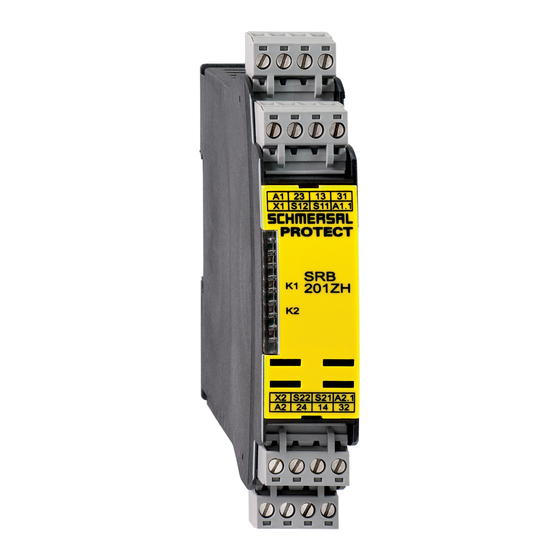
SRB 201ZH
2-channel-selection, with two limit
switches A and B
Power level: 2-channel selection
suitable for contact amplification
and contact multiplication through
contactors or relays with positively
driven contacts.
Wire breakage, cross-shorts and
earth leakage in the monitoring
circuits are detected.
H2 = Feedback loop
Important information:
Contacts of mushroom-push-
buttons must not overlapping. The
NC contact has to be open before
the NO contact is closed, otherwise
the fuses F1 and F2 will blow.
In accordance with Directive 98/37/EC
24 VDC –15%/+10%,
residual ripple max. 10%
Internal electronic fusing,
tripping current > 0.2 A;
F3: tripping current 0.6 A
max. 1.2 W
250 VAC, 6 A ohmic (inductive with
suitable suppressor circuit);
AC-15: 250 VAC/6 A, DC-13: 24 VDC/6 A
6 A slow-blowing
24 VDC, 2 A
2 A slow-blowing
AC-15/DC-13: EN IEC 60947-5-1
≤ 50 ms
≤ 30 ms
AgSnO, self-cleaning, positively driven
max. 100 mOhm in new state
EN IEC 60 664-1 (DIN VDE 0110-1), 4 kV/2
Housing: IP 40, terminals: IP 20,
installation space: IP 54
Single core: rigid or flexible (with or with-
out wire-end ferrules) 0.25 ... 1.5 mm
dual wire with same cross-section:
• plug in or print terminal: rigid or flexible
(with wire-end ferrules without plastic)
0.25 ... 1.5 mm
, flexible (with or
2
without TWIN wire-end ferrule)
0.5 ... 1.5 mm
,
2
• Spring cage terminal: flexible with TWIN
wire-end ferrule 0.5 ... 1.0 mm
0.6 Nm
40 Ohm
100/22.5/121 mm
200 g
–25 °C ... +45 °C
10
switching cycles
7
DIN EN 50 005/DIN 50 013
EN IEC 61 000-6-2, EN IEC 60 947-5-1
EN IEC 60 068-2-6, frequency: 10–55 Hz,
amplitude: 0.35 mm
;
2
Werbung

Verwandte Anleitungen für schmersal SRB 201ZH series


Inhaltszusammenfassung für schmersal SRB 201ZH series
- Seite 1 SRB 201ZH Montage- und Anschlussanleitung / Sicherheitsrelaisbaustein Mounting and wiring instructions / Safety relay module Zweikanalige Ansteuerung, mit zwei 2-channel-selection, with two limit Tastern A und B switches A and B Leistungsebene: Zweikanalige Power level: 2-channel selection Ansteuerung, geeignet zur Kontakt- suitable for contact amplification verstärkung bzw.
- Seite 2 SRB 201ZH Montage- und Anschlussanleitung / Sicherheitsrelaisbaustein Mounting and wiring instructions / Safety relay module LED-Funktionen LED functioning Status Kanal 1 Status of input channel 1 Status of input channel 2 Status Kanal 2 A1 23 13 A1 23 13 X1 S12 S11 A1.1 X1 S12 S11...
- Seite 3 SRB 201ZH Montage- und Anschlussanleitung / Sicherheitsrelaisbaustein Mounting and wiring instructions / Safety relay module Ablaufdiagramm Sequence diagram Operating voltage U Two-hand button A NC contact S11 The diagram refers to the potentials at the terminals of the module. NO contact S12 NC contact S21 Two-hand button B The diagram refers to...
- Seite 4 SRB 201ZH Montage- und Anschlussanleitung / Sicherheitsrelaisbaustein Mounting and wiring instructions / Safety relay module K. A. Schmersal GmbH Telefon +49 (0)202 6474-0 Industrielle Sicherheitsschaltsysteme Telefax +49 (0)202 6474-100 Möddinghofe 30 E-Mail: info@schmersal.de D-42279 Wuppertal Internet: http://www.schmersal.com 09/06...
- Seite 5 SRB 201ZHX3 Montage- und Anschlussanleitung / Sicherheitsrelaisbaustein Mounting and wiring instructions / Safety relay module Zweikanalige Ansteuerung, mit zwei 2-channel-selection, with two limit Tastern A und B switches A and B Leistungsebene: Zweikanalige Power level: 2-channel selection Ansteuerung, geeignet zur Kontakt- suitable for contact amplification verstärkung bzw.
- Seite 6 SRB 201ZHX3 Montage- und Anschlussanleitung / Sicherheitsrelaisbaustein Mounting and wiring instructions / Safety relay module LED-Funktionen LED functioning Status interne Betriebsspannung Status internal power supply (LED leuchtet, wenn die Betriebs- (LED lightening when power supply spannung an den Klemmen A1/A2 is connected to terminal A1/A2) 13 14 31 A2.1...
- Seite 7 SRB 201ZHX3 Montage- und Anschlussanleitung / Sicherheitsrelaisbaustein Mounting and wiring instructions / Safety relay module Ablaufdiagramm Betriebsspannung U Zweihandtaster A Öffner (S11) Die Darstellung bezieht sich auf die Potenziale an den Anschlussklemmen Schließer (S11) des Bausteins Öffner (S21) Zweihandtaster B Die Darstellung bezieht sich auf die Potenziale an den Anschlussklemmen...
- Seite 8 SRB 201ZHX3 Montage- und Anschlussanleitung / Sicherheitsrelaisbaustein Mounting and wiring instructions / Safety relay module K. A. Schmersal GmbH Telefon +49 (0)202 6474-0 Industrielle Sicherheitsschaltsysteme Telefax +49 (0)202 6474-100 Möddinghofe 30 E-Mail: info@schmersal.de D-42279 Wuppertal Internet: http://www.schmersal.com 09/06...
- Seite 9 SRB 200ZHX1 Montage- und Anschlussanleitung / Sicherheitsrelaisbaustein Mounting and wiring instructions / Safety relay module Einkanalige Ansteuerung, mit zwei 1-channel-selection, with two limit Tastern A und B switches A and B Leistungsebene: Zweikanalige Power level: 2-channel selection Ansteuerung, geeignet zur Kontakt- suitable for contact amplification verstärkung bzw.
- Seite 10 SRB 200ZHX1 Montage- und Anschlussanleitung / Sicherheitsrelaisbaustein Mounting and wiring instructions / Safety relay module LED-Funktionen LED functioning Status interne Betriebsspannung Status internal power supply (LED leuchtet, wenn die Betriebs- (LED lightening when power supply spannung an den Klemmen A1-A2 is connected to terminal A1-A2) S23 13 14 S23 13 14...
- Seite 11 SRB 200ZHX1 Montage- und Anschlussanleitung / Sicherheitsrelaisbaustein Mounting and wiring instructions / Safety relay module Ablaufdiagramm Sequence diagram Operating voltage U Button A Input circuit S13-S14 Button B Input circuit S23-S24 Feedback loop Y1-Y2 Output contacts 13/14, 23/24 floating Undisturbed Error in feed- Synchronous operating cycle...
- Seite 12 SRB 200ZHX1 Montage- und Anschlussanleitung / Sicherheitsrelaisbaustein Mounting and wiring instructions / Safety relay module K. A. Schmersal GmbH Telefon +49 (0)202 6474-0 Industrielle Sicherheitsschaltsysteme Telefax +49 (0)202 6474-100 Möddinghofe 30 E-Mail: info@schmersal.de D-42279 Wuppertal Internet: http://www.schmersal.com 09/06...