Werbung
Quicklinks
Montage- und Betriebsanleitung
Installation and Operating Instructions
Mode d´emploi
Montage- en bedieningshandleiding
L1
Istruzioni per l´uso
L2
L3
Instrucciones de montaje de servicio
N
Bruksanvisning för montering och drift
SA/S 4.6.1, SA/S 8.6.1, SA/S 12.6.1
Schaltaktor, 4-, 8-, 12-fach, 6 A
Switch Actuator, 4-, 8-, 12fold, 6 A
Actuateur de commutation, 4-, 8-, 12 fois, 6 A
Schakelactuator, 4-, 8-, 12-voudig, 6 A
Attuatore a, 4-, 8-, 12 livelli, 6 A
ABB i-bus
Actuador interruptor, 4-, 8-, 12 veces, 6 A
Brytaktor, 4-, 8-, 12-kanalig, 6A
ABB i-bus
®
EIB / KNX
2CDG 941 007 P0002
Technische Daten (Auszug)
DE
1
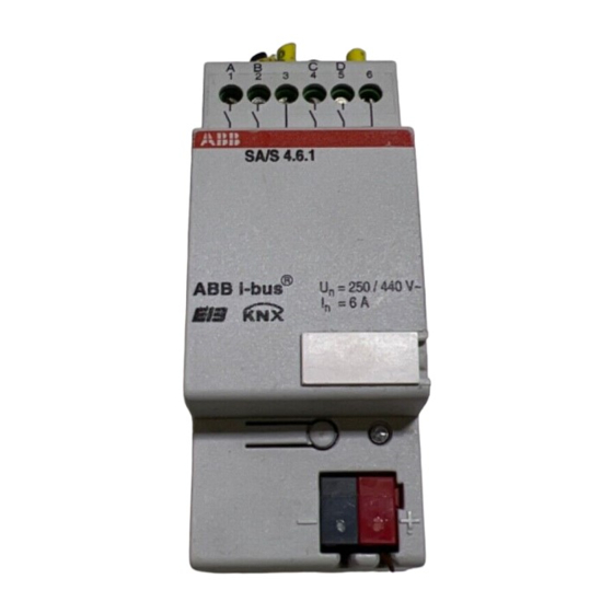
Geräte-Anschluss
Stromversorgung
1 Schilderträger
2 EIB Programmier-Taste
Anschlussklemmen Schraubklemme
3 rote EIB Programmier-LED
4 EIB Anschlussklemme
5 Laststromkreis: je Kontakt 1Schraubklemmen
EIB/KNX Anschluss Busanschlussklemme,
für je 2 Kontakte 1 Schraub-
klemme für Phasenanschluß
Leistungs Ausgänge 4, 8 oder 12 potentialfreie
Schaltspannung
Geräte-Beschreibung
Schaltvermögen
Die 4-, 8- und 12-fach Schaltaktoren sind Reihen-
einbaugeräte im ProM Design. Die Schaltaktoren
Nach DIN EN 60947-4 6A (AC3)
schalten mit 4, 8 bzw. 12 potenzialfreien unabhän-
Temperaturbereich
gigen Kontakten elektrische Verbraucher über ABB
im Betrieb
i-bus
®
EIB / KNX. Die Stromkreise sind in Gruppen
Lagerung
mit 2 Kontakten aufgeteilt.
Transport
Die Geräte werden über den EIB / KNX versorgt
Schutzart
und benötigen keine zusätzliche Stromversor-
Schutzklasse
gung.
Überspannungs-
kategorie
Verschmutzungsgrad 2 nach DIN EN 60664-1
Technical Data (Extract)
1
EN
Connection
Power supply
1 Nameplate holder
2 EIB programming key
Connection terminals Screw terminal
3 Red EIB programming LED
4 EIB connection terminal
5 Power circuit: 1 screw terminal each per contact
EIB / KNX connection Bus terminal connection,
for every 2 contacts, 1 screw
terminal for phase connection
Power outputs
Description of the Device
Switching voltage
The 4, 8 and 12-pole switch actuators are series
Switching capacity under DIN EN 60669
devices in the ProM design to be built in. The
switch actuators with 4, 8 or 12 potential-free in-
Under DIN EN 60947-4 6A (AC3)
dependent contacts switch electric loads.
Temperature range
The current circuits are arranged in groups with 2
in operation
contacts.
Storage
The devices are supplied with power through the
Transport
EIB / KNX and require no additional power supply.
Type of protection
Protection class
Overvoltage category III under DIN EN 60664-1
Degree of
contamination
Caractéristiques techniques (extrait)
1
FR
Raccordement
Alimentation en courant via ABB i-bus
1 Porte-plaques signalétiques
2 Touche de programmation EIB
Bornes de raccordement Borne de raccordement
3 DEL de programmation EIB rouge
4 Borne de raccordement EIB
5 Circuit de courant
Raccordement EIB/KNX Borne de raccordement
de charge:
pour chaque contact 1 borne
à vis pour 2 contacts 1 borne
Sorties de puissance 4, 8 ou 12 contacts
à vis pour le raccordement
de phase.
Tension de commutation 250/440 VAC
Pouvoir de commutation selon DIN EN 60669
Description de l'appareil
230V: 6A (AC1),
Les actionneurs de commutation 4, 8 et 12 fois
selon DIN EN 60947-4 6A (AC3)
sont des appareils pour un montage en série réa-
Plage de température
lisés en design ProM. Les actionneurs de com-
en service
mutation commutent par 4, 8 resp. 12 contacts
stockage
indépendants et exempts de potentiel des con-
transport
sommateurs électriques. Les circuits de courant
Protection
sont répartis en groupes de 2 contacts.
Degré de protection II selon DIN EN 61 140
Les appareils sont alimentés par le EIB / KNX,
Catégorie de surtension III selon DIN EN 60664-1
par conséquent, toute alimentation en courant
Degré de salissure
supplémentaire est superfl ue. superfl ue.
1
A
B
C
D
E
F
G
H
I
J
K
L
5
1
2
3
4
5
6
7
8
9
10
11
12
13
14
15
16
17
18
SA/S 12.6.1
1
®
U
= 250 / 440 V~
n
I
= 6 A
n
SA/S 4.6.1
2
B 36 mm
3
2 TE
4
Bedienung und Anzeige
über ABB i-bus
®
EIB / KNX
Programmier-LED (3)
(21...30 V DC)
leuchtet rot, wenn das Gerät im
Programmiermodus ist (Nachdem
0,2... 2,5 mm
2
feindrähtig
der Programmiertaster (2) gedrückt
0,2... 4 mm
2
eindrähtig
wurde).
schraubenlos
Kontakte
250/440 VAC
nach DIN EN 60669
230V: 6A (AC1),
-5° C ... + 45° C
-25° C ... + 55° C
-25° C ... + 70° C
IP20 nach DIN EN 60529
II nach DIN EN 61140
III nach DIN EN 60664-1
Operation and Display
Through ABB i-bus
®
EIB / KNX
Programming-LED (3)
(21...30 V DC)
lights up red when the device is in
the programming mode of operation
2
0,2... 2,5 mm
fi ne wire
(after the Programming button (2)
2
0.2... 4 mm
single wire
has been pressed).
screwless
4, 8 or 12
potential-free contacts
250/440 VAC
230V: 6A (AC1),
-5° C ... + 45° C
-25° C ... + 55° C
-25° C ... + 70° C
IP20 in acc. DIN EN 60 529
II under DIN EN 61 140
2 under DIN EN 60664-1
Commande et affi chage
®
EIB / KNX
DEL de programmation (3)
(21...30 V cc)
Lumière rouge allumée lorsque
l'appareil est en mode de program-
0,2... 2,5 mm
2
à fi ls fi ns
mation (une fois que la touche de
0,2... 4 mm
2
à un fi l
programmation (2) a été enfoncée).
de bus sans vis
à potentiel fl ottant
-5° C ... + 45° C
-25° C ... + 55° C
-25° C ... + 70° C
IP20 selon DIN EN 60 529
2 selon DIN EN 60664-1
58
B
6.5
43.5
A
B
C
D
E
F
G
H
1
2
3
4
5
6
7
8
9
10
11
12
SA/S 8.6.1
®
ABB i-bus
U
= 250 / 440 V~
n
I
= 6 A
n
IP20
SA/S 8.6.1
SA/S 12.6.1
72 mm
108 mm
4 TE
6 TE
-5 °C
Montage
Das Gerät ist geeignet zum Einbau in Verteilern
oder Kleingehäusen für Schnellbefestigung auf
35 mm Tragschienen, nach DIN EN 60715.
Die Zugänglichkeit des Gerätes zum Betreiben,
Prüfen, Besichtigen, Warten und Reparieren
muss sichergestellt sein.
Anschluss
Der elektrische Anschluss erfolgt über Schraub-
klemmen. Die Klemmenbezeichnungen befi nden
sich auf dem Gehäuse.
Die Verbindung zum EIB erfolgt mit der mit-
gelieferten Busanschlussklemme.
Inbetriebnahme
Die Vergabe der physikalischen Adresse, sowie
das Einstellen der Parameter erfolgt mit der
Engineering Tool Software ETS (ab Version
ETS2V1.3).
Für die Programmierung in der ETS3 ist das
entsprechende VD3-File zu verwenden
Installation
The device is suitable for installation in distribution
boxes or small housings for quick mounting on
35 mm support rails in compliance with DIN
EN 60715. The accessibility of the device for
operation, testing, inspection, maintenance and
repair must be ensured.
Connection
The electrical connections are made using
screw terminals. The connection to the EIB /
KNX is made using the bus connection terminal
supplied. The terminal names are found on the
housing.
Commissioning
The assignment of the physical address and the
setting of the parameters are performed with the
ETS Engineering Tool Software (Version ETS2
V1.3 or higher).
The appropriate VD3 fi le is to be used for the
programming in the ETS3.
Montage
L'appareil se prête à un montage dans des
tableaux de distribution ou dans de petits boîtiers
destinés à une fi xation rapide sur des profi lés
support de 35 mm, selon DIN EN 60715. Il est
indispensable que l'accessibilité de l'appareil
soit assurée pour les tâches d'exploitation, de
vérifi cation, de visite, d'entretien, de maintenance
et de réparation.
Connexion
La connexion électrique s'effectue au moyen
de bornes à vis. La liaison au EIB / KNX s'opère
par la borne de raccordement de bus fournie.
Les désignations des bornes sont apposées
sur le boîtier.
Mise en service
L'assignation de l'adresse physique ainsi que
le réglage des paramètres se réalisent avec le
logiciel Engineering Tool Software ETS (à partir
de la version ETS2 V1.3).
Pour la programmation dans le ETS3, il convi-
ent d'utiliser le fi chier VD3 approprié.
+45 °C
Eine ausführliche Beschreibung der Para-
metrierung und Inbetriebnahme fi nden Sie in den
technischen Daten des Gerätes.
Diese fi nden Sie zum Download im Internet unter
www.abb.de/eib.
Wichtige Hinweise
Montage und Inbetriebnahme darf nur von
Elektrofachkräften ausgeführt werden. Bei der
Planung und Errichtung von elektrischen Anlagen
sind die einschlägigen Normen, Richtlinien,
Vorschriften und Bestimmungen zu beachten.
- Gerät bei Transport, Lagerung und im Betrieb
vor Feuchtigkeit, Schmutz und Beschädigung
schützen!
A detailed description of the parameter
configuration and commissioning steps can
be found in the technical data. This information
can be downloaded from the Internet site www.
abb.de/eib.
Important notes
Installation and commissioning of the device may
only be carried out by trained electricians. The
relevant standards, directives, regulations and
instructions must be observed when planning
and implementing the electrical installation.
- Protect the device against moisture, dirt and
damage during transport, storage and
operation!
Vous trouverez une description détaillée du
paramétrage et de la mise en service dans la
documentation technique de l'appareil. Vous
pouvez télécharger celles ci par Internet, sur le
site www.abb.de/eib.
Remarques importantes
L'installation et le montage ne doivent être
effectués que par des électriciens qualifi és. Les
normes, directives, règlements et stipulations
en vigueur doivent être respectés lors de la
planifi cation et de la mise en place d'installations
électriques.
- Protéger l'appareil de l'humidité, de la saleté
et de dommage lors du transport, du
stockage et de l'utilisation !
ABB STOTZ-KONTAKT GmbH
Eppelheimer Straße 82, 69123 Heidelberg,
Germany
Postfach 10 16 80, 69006 Heidelberg,
Germany
+49 (0) 6221 701 607
+49 (0) 6221 701 724
www.abb.de/stotz-kontakt
Technische Hotline / Technical Support:
+49 (0) 6221 701 434
E-Mail: eib.hotline@de.abb.com
- Gerät nur innerhalb der spezifi zierten
technischen Daten betreiben!
- Gerät nur im geschlossenen Gehäuse
(Verteiler) betreiben!
Reinigen
Verschmutzte Geräte können mit einem trockenen
Tuch gereinigt werden. Reicht dies nicht aus, kann
ein mit Seifenlösung leicht angefeuchtetes Tuch
benutzt werden. Auf keinen Fall dürfen ätzende
Mittel oder Lösungsmittel verwendet werden.
Wartung
Das Gerät ist wartungsfrei. Bei Schäden (z.B. durch
Transport, Lagerung) dürfen keine Reparaturen
vorgenommen werden.
Beim Öffnen des Gerätes erlischt der Garantie-
anspruch!
- Do not operate the device outside the specifi ed
technical data (e.g. Temperature range)!
- The device may only be operated in closed
enclosures (e.g. distribution boards)
Cleaning
Should the device become soiled, it may be cleaned
with a dry cloth. If this does not suffi ce, a cloth
lightly moistened with soap solution may be used.
On no account should caustic agents or solvents
be used.
Maintenance
The device is maintenance free. Should damage
have occurred, e.g. due to transport or storage, no
repairs should be carried out.
The warranty expires if the device is opened!
- N'utiliser l'appareil que dans le cadre des
caractéristiques techniques spécifi ées !
- N'utiliser l'appareil que dans un boîtier fermé
(coffret) !
Nettoyage
Les appareils sales peuvent être nettoyés à l'aide
d'un chiffon sec. Si cela ne suffi t pas, un chiffon
légèrement imprégné de solution savonneuse peut
être utilisé. N'utiliser en aucun cas des produits
caustiques ou des solvants.
Entretien
L'appareil ne nécessite aucun entretien. En cas de
dommage (par ex. lors du transport, du stockage),
aucune réparation ne doit être entreprise.
L'ouverture de l'appareil annule la garantie !
Werbung

Verwandte Anleitungen für ABB SA/S 8.6.1


Inhaltszusammenfassung für ABB SA/S 8.6.1
- Seite 1 Montage- en bedieningshandleiding Istruzioni per l´uso 43.5 Instrucciones de montaje de servicio Bruksanvisning för montering och drift SA/S 4.6.1, SA/S 8.6.1, SA/S 12.6.1 SA/S 8.6.1 Schaltaktor, 4-, 8-, 12-fach, 6 A ® Switch Actuator, 4-, 8-, 12fold, 6 A ABB i-bus...
- Seite 2 I dati tecnici dell’apparecchio, che possono Impiego e visualizzazione 0,2... 2,5 mm a cavo sottile 4 Morsetto EIB azionamento, verifi ca, ispezione, manutenzione essere scaricati da Internet all’indirizzo www.abb. Pulizia 0,2... 4 mm monocavo LED di programmazione (3) 5 Circuito elettrico e riparazione deve essere garantita.