Herunterladen Inhalt Inhalt Diese Seite drucken
Inhaltsverzeichnis

Werbung

Verfügbare Sprachen
  • DE

Verfügbare Sprachen

  • DEUTSCH, seite 1
DALIeco Control

Werbung

Inhaltsverzeichnis
loading

Inhaltszusammenfassung für OSRAM DALIeco Control

  • Seite 1 DALIeco Control...
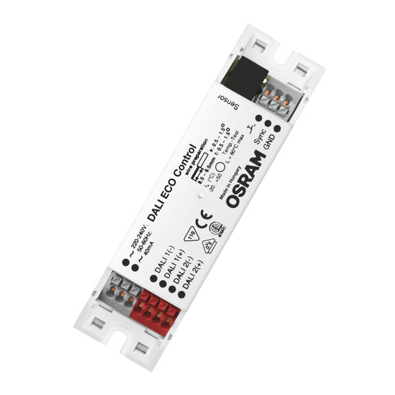
  • Seite 2   4,1 mm  220-240V; 50-60Hz; 40mA DALI 1(-) DALI 1(+) Sync DALI 2(-) DALI 2(+)
  • Seite 3  220-240V; 50-60Hz; 40mA DALI 1(-) DALI 1(+) Sync DALI 2(-) DALI 2(+) QTi DALI ECG CH-1 QTi DALI ECG CH-2  220-240V; 50-60Hz; 40mA DALI 1(-) DALI 1(+) Sync DALI 2(-) DALI 2(+)
  • Seite 4  220-240V; 50-60Hz; 40mA DALI 1(-) DALI 1(+) Sync DALI 2(-) DALI 2(+) QTi DALI ECG CH-1 QTi DALI ECG CH-2 DALI Professional LS / P D LI A nalog S ensor Sensor coupler...
  • Seite 5  Master Remote User Remote Sensor select test Switch off delay 1 sec 1 min 30 sec 3 min 5 min 10 min 15 min 30 min 60 min Macro Recorder PROG Holiday Resume 100 h Offset Burn-in PC modes CH-1 CH-2 CH-1...
  • Seite 6  DALIeco Open-Plan Office Corridor Sensor select test Switch off delay 1 sec 30 sec 1 min 3 min 5 min 10 min 15 min 30 min 60 min PROG Macro Recorder PROG Single Office (default) Meetingroom / Classroom 100 h Burn-in PC modes Offset...
  • Seite 7  CH-2 30 % OFFSET DALI2 PROG CH-1 DALI1 REGULATED Single Office time 15 min. (default)  STANDBY 30 % OFFSET CH-2 DALI2 PROG CH-1 DALI1 REGULATED 30 % OFFSET 30 % REGULATED time 15 min. 60 min. Open Plan Office...
  • Seite 8  STANDBY STANDBY 100 % CH-2 DALI2 PROG CH-1 DALI1 10 % 10 % time 5 min. Corridor  CH-2 30 % OFFSET DALI2 CH-1 PROG DALI1 REGULATED time Semi 15 min. Meetingroom / Classroom Auto...
  • Seite 9  STANDBY 100 % CH-2 DALI2 PROG CH-1 DALI1 30 % time 15 min. 5 min. Sanitary Room  STANDBY 100 % CH-2 DALI2 PROG CH-1 DALI1 50 % time 5 min. 1 min. Staircase...
  • Seite 10: Inhaltsverzeichnis

    DALIeco Control - Installation und Bedienung Inhaltsverzeichnis Allgemeine Hinweise .................11 5.6 Testfunktion ..................15 1.1 Symbole und Abkürzungen in dieser Anleitung ........11 5.7 Stand-by-level ..................15 1.2 Bestimmungsgemäße Verwendung .............11 5.8 Stand-by-time ..................16 Montage und Installation ..............11 5.9 Tageslicht- und Präsenzfunktionen ........16 2.1 Anschlussbelegung der Steuereinheit ........11 5.10 Offset einstellen ...................16  2.2 Abmessungen und Montagemaße ...........11 5.11 100 h Burn-in ..................16 ...
  • Seite 11: Allgemeine Hinweise

    Allgemeine Hinweise Montage und Installation 1.1 Symbole und Abkürzungen in dieser Anleitung 2.1 Anschlussbelegung der Steuereinheit  • Listenpunkt, Aufzählung Netzanschluss nummerierte Handlungsschritte mit vorgegebener Reihenfolge Netzanschluss Verweis auf Abschnitt (z.B. 2.2) bzw. separate Anleitung (dann ohne Ziffern) nicht belegt ...
  • Seite 12: Einbindung Von Tastern Über Tasterkoppler

    2.6.1 Einbindung von Tastern über Tasterkoppler Nach Abschluss des Rücksetzvorgangs schaltet die Beleuchtung kurz auf 100% , danach Taster können über Tasterkoppler ohne weitere Inbetriebnahme an die DALI Leitung angeschlos- wird wieder der ursprüngliche Wert eingestellt. senen werden. Jeder angeschlossene Tasterkoppler verfügt über vier Eingänge (A-D ). 2.6.2 Einbindung von Sensoren über Sensorkoppler Grundeinstellung des Tasterkopplers Sensoren können über Sensorkoppler ohne weitere Inbetriebnahme an die DALI Leitung ange-...
  • Seite 13: Funktion Und Externe Komponenten

    Funktion und externe Komponenten Bedienung 3.1 Grundsätzliche Funktionsweise Beschreibung aller Tasten/LEDs der Master Remote und deren Funktionen, die keine Verwendung Die Steuereinheit verändert/schaltet die Beleuchtung an Arbeitsplätzen, in Fluren und anderen der Taste [PROG] erfordern, sowie Beschreibung aller Tasten/LED der User Remote und deren gemeinsam genutzten Räumen in Abhängigkeit von nutzbarem Tageslicht und Anwesenheit/Be- Grundfunktionen.
  • Seite 14: Fernbedienung User Remote

    Schritt-für-Schritt System-Programmierung 4.2 Fernbedienung User Remote (und separate Anleitung)   mittels Master Remote Tasten / LED (21) [ON/OFF] alle Leuchten ein/aus (22) Signalisierung LED (grün/rot/orange) Programmierung bzw. Konfiguration erfolgen mittels Master Remote bzw. direkt am Sensor. (23) [1] Szenen-Taste 1 Bei Tastendruck Master Remote stets auf den entsprechenden Sensor richten.
  • Seite 15: Funktionsmodi  8

    5.2 Funktionsmodi 5.5 Switch off delay (Nachlaufzeit)  Schaltverhalten der vorkonfigurierten Funktionsmodi: Diagramme 14 . Timer wird bis zum Verlassen des „ON“ Zustandes (Wechsel zu „STANDBY“ oder „OFF“) nach   der letzten Präsenzerkennung eingestellt. In den Funktionsmodi „Corridor“, „Staircase“ u. •...
  • Seite 16: Stand-By-Time

    5.8 Stand-by-time 5.10 Offset einstellen Zeitdauer des STANDBY einstellen bzw. die STANDBY Funktion dauerhaft einschalten. Der OFFSET (= Abstand von CH-2 zu CH-1) eines bestimmten Funktionsmodus einstellen.  100 h Stand-by-time • Eine der Tasten [Stand-by-time] drücken (SP oder LP), um Taste [Offset] drücken (SP).
  • Seite 17: Sensor Select

    System-Bedienung mittels User Remote 5.12 Sensor select Taste [Sensor select] drücken (LP), um einen Sensor auszu- Bei Tastendruck User Remote stets auf den entsprechenden Sensor richten. wählen (LED des ausgewählten Sensors blinkt orange). Sensor 6.1 Szene-Tasten [1] bis [4] LED-Anzeige am Sensor: ...
  • Seite 18: Unabhängige Bedienung Mehrerer Systeme

    Technische Daten 6.4 Unabhängige Bedienung mehrerer Systeme Anlernen der User Remote auf einen bestimmten, ausgewählten Empfänger, um eine unabhängi- Netzanschluss 220 – 240 V AC 50-60 Hz ge Bedienung mehrerer Systeme (maximal 15) im gleichen Raum zu ermöglichen. Eingang Taster Potenzialfreie Schließerkontakte, Tasten [CH-1 ] + [CH-2 ] zeitgleich drücken (VLP), um max.
  • Seite 20 DALIeco Control - Installation and Operation Contents General....................21 5.9 Daylight and motion-sensing functions .........26 1.1 Symbols and abbreviations in these instructions........21 5.10 Setting offset ..................26 1.2 Intended use ..................21 5.11 100 h Burn-in ..................26 5.12 Sensor select ..................26 Mounting and installation ..............21 5.13 PC modes ....................27 2.1 Connection allocation in the control unit .........21 5.14 Macro Recorder ..................27  2.2 Dimensions and mounting dimensions ........21...
  • Seite 21: General

    General Mounting and installation 1.1 Symbols and abbreviations in these instructions 2.1 Connection allocation in the control unit  • Bullet point, listing Mains connection Numbered steps with stipulated sequence Mains connection Cross-reference to Section (e.g. 2.2) or separate instructions (but then without figures) Spare ...
  • Seite 22: Integration Of Push-Buttons Via Push-Button Coupler

    2.6.1 Integration of push-buttons via push-button coupler After the reset process is complete, the lighting briefly switches to 100% and then the original Push-buttons can be connected via push-button couplers without additional commissioning to value is set again. the DALI line. Each connected push-button coupler has four inputs (A-D). 2.6.2 Integration of sensors via sensor coupler Basic setting of the push-button coupler Sensors can be connected to the DALI line via the sensor coupler without additional...
  • Seite 23: Function And External Components

    Function and external components Operation 3.1 Fundamental operating principle Description of all push-buttons/LEDs of the Master Remote and its functions that do not require The control unit changes/switches the lighting at workplaces, in corridors and other common use of the [PROG] push-button, and description of all push-buttons/LEDs of the User Remote rooms depending on the usable daylight and the presence/motion of persons.
  • Seite 24: User Remote Remote Control

    Step-by-step system programming using Master Remote 4.2 User Remote remote control (and separate instructions)   Push-buttons / LED Programming or configuration is carried out using Master Remote or directly at the sensor. (21) [ON/OFF] All luminaires on/off When pressing the Master Remote push-button always point to the relevant sensor. (22) LED signalization (green/red/orange) (23) [1] Scene push-button 1 (24) [3] Scene push-button 3...
  • Seite 25: Function Modes  8

    5.2 Function modes 5.5 Switch off delay (overrun time)  Switching behavior of the preconfigured function modes: Diagrams 14 . The timer is set until exiting the "ON" condition (change to "STANDBY" or "OFF") according to   the last detection of motion. In the function modes "Corridor", "Staircase" and "Sanitary", the •...
  • Seite 26: Stand-By-Time

    5.8 Stand-by-time 5.10 Setting offset Set the duration of STANDBY or switch the STANDBY function to continuous. Setting the OFFSET (=distance from CH-2 to CH-1) of a specific function mode. 100 h Stand-by-time • Press one of the push-buttons [Stand-by-time] (SP or LP) to Press push-button [Offset] (SP).
  • Seite 27: Pc Modes

    System operation using User Remote 5.12 Sensor select Press push-button [Sensor select] (LP) to select a sensor When pressing the User Remote push-button always point to the relevant sensor. (LED on selected sensor flashes orange). Sensor 6.1 Scene push-buttons [1] to [4] LED display on sensor: ...
  • Seite 28: Independent Operation Of Several Systems

    Technical data 6.4 Independent operation of several systems Teaching of the User Remote to a specific selected receiver in order to permit independent Mains connection 220 – 240 V AC 50-60 Hz operation of several systems (maximum 15) in the same room. Push-button input Floating NO contacts, Simultaneously press push-buttons [CH-1 ] + [CH-2 ]...
  • Seite 30 DALIeco Control - Instalación y funcionamiento Índice Indicaciones generales ..............31 5.9 Funciones de luz diurna y de presencia ........36 1.1 Símbolos y abreviaturas en el presente manual .........31 5.10 Ajustar Offset ..................36 1.2 Uso previsto..................31 5.11 100 h de quemado inicial ..............36 5.12 Sensor select ..................37 Montaje e instalación ................31 5.13 PC modes ....................37 2.1 Asignación de conexiones de la unidad de control ....31 5.14 Macro Recorder ..................37  2.2 Dimensiones y medidas de montaje ........31 ...
  • Seite 31: Indicaciones Generales

    Indicaciones generales Montaje e instalación 1.1 Símbolos y abreviaturas en el presente manual 2.1 Asignación de conexiones de la unidad de control  • Punto en la lista, enumeración Conexión a la red Pasos de procedimiento numerados con orden predeterminado Conexión a la red Referencia a apartado (p.
  • Seite 32: Integración De Pulsadores A Través De Acopladores De Pulsadores

    2.6.1 Integración de pulsadores a través de acopladores de pulsadores Una vez concluido el proceso de restablecimiento, la iluminación cambia brevemente al 100 %, Los pulsadores pueden conectarse a la línea DALI mediante acopladores de pulsadores sin otra a continuación se ajusta de nuevo el valor de partida. puesta en marcha.
  • Seite 33: Función Y Componentes Externos

    Función y componentes externos Funcionamiento 3.1 Principio de funcionamiento básico Descripción de todas las teclas/LED del Master Remote y sus funciones que no requieren un La unidad de control modifica/conmuta la iluminación de lugares de trabajo, pasillos y otras uso de la tecla [PROG], así como la descripción de todas las teclas/LED del User Remote y sus salas de uso común en función de la luz diurna aprovechable y la presencia/el movimiento de las funciones básicas.
  • Seite 34: Mando A Distancia User Remote

    Programación de sistema paso a paso 4.2 Mando a distancia User Remote manual específico)   mediante el Master Remote Teclas / LED (21) [ON/OFF] todas las luminarias conectadas/desconectadas (22) Señalización LED (verde/rojo/naranja) La programación o configuración se lleva a cabo mediante el Master Remote o directamente en (23) [1] tecla escenas 1 el sensor.
  • Seite 35: Modos De Funcionamiento  8

    5.2 Modos de funcionamiento 5.5 Switch off delay (tiempo de retardo de desconexión)  Comportamiento de conmutación de los modos de función preconfigurados: Diagramas El temporizador se ajusta tras la última detección de presencia hasta abandonar el estado "ON"  hasta 14 .
  • Seite 36: Stand-By-Time

    5.8 Stand-by-time 5.10 Ajustar Offset Ajustar la duración del STANDBY o conectar la función STANDBY de forma permanente. Ajustar el OFFSET (= distancia de CH-2 a CH-1) de un modo de funcionamiento determinado. 100 h Stand-by-time • Pulsar una de las teclas [Stand-by-time] (SP o LP) con el fin Pulsar la tecla [Offset] (SP).
  • Seite 37: Sensor Select

    Funcionamiento del sistema mediante User Remote 5.12 Sensor select Pulsar la tecla [Sensor select] (LP) para seleccionar un En caso de pulsar la tecla del User Remote, orientarlo siempre hacia el sensor correspondiente. sensor (el LED del sensor seleccionado parpadea). Sensor 6.1 Teclas de escenas [1] a [4] Indicación LED en el sensor:...
  • Seite 38: Funcionamiento Independiente De Varios Sistemas

    Datos técnicos 6.4 Funcionamiento independiente de varios sistemas Programación del User Remote para un receptor determinado seleccionado, con el fin de permi- Conexión a red 220 – 240 V CA 50-60 Hz tir un funcionamiento independiente de varios sistemas (máximo 15) en el mismo espacio. Entrada de pulsador Contacto de cierre flotante, Pulsar simultáneamente las teclas [CH-1 ] + [CH-2 ]...
  • Seite 40 DALIeco Control - Installation et utilisation Sommaire Remarques générales ...............41 5.9 Fonctions lumière du jour et présence ........46 1.1 Symboles et abréviations de cette notice ...........41 5.10 Régler l'offset ..................46 1.2 Utilisation conforme ................41 5.11 100 h Burn-in ..................46 5.12 Sensor select ..................47 Montage et installation ..............41 5.13 PC modes ....................47 2.1 Occupation des branchements de l'unité de commande ..41 5.14 Macro Recorder ..................47  2.2 Dimensions et mesures de montage ........41...
  • Seite 41: Remarques Générales

    Remarques générales Montage et installation 1.1 Symboles et abréviations de cette notice 2.1 Occupation des branchements de l'unité de commande  • Point de liste, énumération Branchement secteur Étapes de procédure numérotées avec ordre prédéterminé Branchement secteur Renvoi à la section (p. ex. 2.2) ou à une notice séparée (alors sans chiffre) non occupé...
  • Seite 42: Intégration De Boutons-Poussoirs Via Le Coupleur De Boutons-Poussoirs

    2.6.1 Intégration de boutons-poussoirs via le coupleur de boutons-poussoirs Après ce processus de réinitialisation, l'éclairage commute brièvement sur 100 % et Des boutons-poussoirs peuvent être raccordés via le coupleur de boutons-poussoirs sans autre est réglé de nouveau à sa valeur initiale. mise en service de la ligne DALI.
  • Seite 43: Fonction Et Composants Externes

    Fonction et composants externes Utilisation 3.1 Fonctionnement de base Description de toutes les touches/LED du Master Remote et de leurs fonctions qui ne requièrent L'unité de commande modifie/commute l'éclairage sur les postes de travail, dans les couloirs et pas l'utilisation de la touche [PROG] ainsi que la description de toutes les touches /LED du User autres espaces communs en fonction de la lumière du jour et de la présence/du mouvement de Remote et de leurs fonctions de base.
  • Seite 44: (Et Notice Séparée)

    Système de programmation étape par étape 4.2 Télécommande Master User notice séparée)   via Master Remote Touches/LED (21) [ON/OFF] Tous les éclairages on/off (22) Signalisation LED (vert/rouge/orange) La programmation du système est effectuée via Master Remote ou directement sur la cellule. (23) [1] Touche scène 1 En appuyant sur la touche Master Remote, toujours pointer vers la cellule correspondante.
  • Seite 45: Modes De Fonctionnement

    5.2 Modes de fonctionnement 5.5 Switch off delay (temporisation)  Comportement de commutation des modes de fonctionnement préconfigurés : Diagrammes Minuterie active jusqu'à la fin de l'état « ON » (passage à « stand-by » ou « OFF ») après la jusqu'à...
  • Seite 46: Stand-By-Time

    5.8 Stand-by-time 5.10 Régler l'offset Régler la durée du STANDBY ou activer durablement la fonction STANDBY. Régler l'OFFSET (= distance de CH-2 à CH-1) d'un mode de fonctionnement particulier. 100 h Stand-by-time • Appuyer sur l'une des touches [Stand-by-time] (SP ou LP), Appuyer sur [Offset] (SP).
  • Seite 47: Sensor Select

    Utilisation du système avec User Remote 5.12 Sensor select Appuyer sur [Sensor select] (LP), pour sélectionner une En appuyant sur User Remote, toujours pointer vers la cellule correspondante. cellule (la LED de la cellule sélectionnée clignote en orange). Sensor 6.1 Touches scène [1] à [4] Affichage LED sur la cellule : ...
  • Seite 48: Utilisation Indépendante De Plusieurs Systèmes

    Caractéristiques techniques 6.4 Utilisation indépendante de plusieurs systèmes Adapter l'User Remote à un récepteur précis sélectionné pour une utilisation indépendante de Raccordement électrique 220 – 240 V CA 50-60 Hz plusieurs systèmes (maximal 15) dans une même pièce. Entrée boutons Contacts de fermeture sans potentiel Appuyer en même temps sur [CH-1 ] + [CH-2 ] (VLP) Longueur de câble max.
  • Seite 50 DALIeco Control - Installazione e uso Indice Indicazioni generali................51 5.9 Funzioni luce diurna e presenza ..........56 1.1 Simboli e abbreviazioni delle presenti istruzioni........51 5.10 Regolazione dell'offset ................56 1.2 Uso conforme a destinazione ..............51 5.11 100 h Burn-in ..................56 5.12 Sensor select ..................57 Montaggio e installazione ..............51 5.13 PC modes ....................57 2.1 Assegnazione dei collegamenti dell'unità di comando ...51 5.14 Macro Recorder ..................57 ...
  • Seite 51: Indicazioni Generali

    Indicazioni generali Montaggio e installazione 1.1 Simboli e abbreviazioni delle presenti istruzioni 2.1 Assegnazione dei collegamenti dell'unità di comando  • Voce di un elenco, enumerazione Collegamento alla rete Fase di lavoro numerata con sequenza prestabilita Collegamento alla rete Rimando a sezione (ad es. 2.2) o istruzione separata (in tal caso senza numeri) Non occupato ...
  • Seite 52: Integrazione Di Pulsanti Mediante Accoppiatori Pulsante

    2.6.1 Integrazione di pulsanti mediante accoppiatori pulsante Al termine dell'operazione di ripristino l'illuminazione passa brevemente al 100%, poi È possibile collegare pulsanti alla linea DALI mediante accoppiatori tasti senza ulteriore messa in viene impostato di nuovo il valore originario. servizio. Ogni accoppiatore pulsante collegato dispone di quattro ingressi (A-D). 2.6.2 Integrazione di sensori mediante accoppiatori sensore Impostazione di base dell'accoppiatore pulsante Mediante accoppiatori sensore è...
  • Seite 53: Funzione E Componenti Esterni

    Funzione e componenti esterni 3.1 Modo di funzionamento di principio Descrizione di tutti i pulsanti/LED del Master Remote e delle relative funzioni che non richie- L'unità di comando cambia/commuta l'illuminazione in posti di lavoro, corridoi e altri spazi dono l'utilizzo del tasto [PROG], nonché descrizione di tutti i pulsanti/LED dell'User Remote comuni in funzione della luce diurna utile e della presenza/del movimento delle persone.
  • Seite 54: Telecomando User Remote

    Programmazione del sistema passo a passo 4.2 Telecomando User Remote istruzioni separate)   con Master Remote Tasti / LED (21) [ON/OFF] tutte le lampade on/off (22) segnalazione LED (verde/rosso/arancione) La programmazione o configurazione avvengono per mezzo del Master Remote o direttamente (23) [1] tasto scene 1 dal sensore.
  • Seite 55: Modalità Di Funzionamento  8

    5.2 Modalità di funzionamento 5.5 Switch off delay (ritardo di spegnimento)  Comportamento di commutazione delle modalità di funzionamento preconfigurate: Diagrammi da Il timer viene impostato dopo l'ultimo rilevamento della presenza fino all'uscita dallo stato "ON" 14 . (passaggio a "STANDBY" o "OFF"). Nelle modalità di funzionamento "Corridor", "Staircase" e ...
  • Seite 56: Stand-By-Time

    5.8 Stand-by-time 5.10 Regolazione dell'offset Impostare la durata dello STANDBY o attivare permanentemente la funzione STANDBY. Regolare l'OFFSET (= intervallo da CH-2 a CH-1) di una determinata modalità di funzionamento.  100 h Stand-by-time • Premere uno dei tasti [Stand-by-time] (SP o LP) per impostare Premere il tasto [Offset] (SP).
  • Seite 57: Sensor Select

    Uso del sistema mediante User Remote 5.12 Sensor select Premere il tasto [Sensor select] (LP) per selezionare un sen- Quando si premono i tasti, puntare sempre l'User Remote verso il sensore in questione. sore (il LED del sensore selezionato lampeggia in arancione). Sensor 6.1 Tasti scena da [1] a [4] Indicazione LED del sensore:...
  • Seite 58: Uso Indipendente Di Più Sistemi

    Dati tecnici 6.4 Uso indipendente di più sistemi Sintonizzazione dell'User Remote su un determinato ricevitore selezionato, in modo da consenti- Collegamento alla rete elettrica 220 – 240 V AC 50-60 Hz re l'uso indipendente di più sistemi (massimo 15) nello stesso ambiente. Ingresso pulsante Contatti di chiusura a potenziale zero, Premere contemporaneamente i tasti [CH-1 ] + [CH-2 ]...
  • Seite 60 OSRAM GmbH Steinerne Furt 62 86167 Augsburg, Germany www.osram.com...

Inhaltsverzeichnis