Herunterladen Inhalt Inhalt Diese Seite drucken

Werbung

Verfügbare Sprachen
  • DE

Verfügbare Sprachen

  • DEUTSCH, seite 56
KIT VIDEO WAY SLIM 1-2 L
1-2 L WAY SLIM VIDEO KIT
KIT VIDEO WAY SLIM 1-2 BP
VIDEO SET WAY FÜR 1-2 FAMHAUS
KIT VIDEO WAY SLIM 1-2 L
MANUAL DE INSTALADOR Y USUARIO
USER & INSTALLER'S MANUAL
MANUEL D'INSTALLATION ET UTILISATION
INSTALLATIONS-UND BENUTZERHANDBUCH
MANUAL DO INSTALADOR E DO UTILIZADOR

Werbung

Inhaltsverzeichnis
loading

Inhaltszusammenfassung für Fermax WAY SLIM 1-2 L

  • Seite 1 KIT VIDEO WAY SLIM 1-2 L 1-2 L WAY SLIM VIDEO KIT KIT VIDEO WAY SLIM 1-2 BP VIDEO SET WAY FÜR 1-2 FAMHAUS KIT VIDEO WAY SLIM 1-2 L MANUAL DE INSTALADOR Y USUARIO USER & INSTALLER’S MANUAL MANUEL D’INSTALLATION ET UTILISATION...
  • Seite 2 1. Monitor 1.1 Botones Micrófono Pantalla LCD Puntos de anclaje Conectores RING Botón Botón Altavoz autoencendido abrepuertas RING 1.2 Funciones Pantalla LCD táctil Muestra la imagen de video de la cámara de la placa. Botón abrepuertas Pulsar para abrir la puerta. Activación de Pulsar para realizar comunicación manos libres con el visitante.
  • Seite 3: Botones Y Funciones

    2. Placa 2.1 Botones y funciones Cámara Camera Lens Altavoz Speaker Leds Night Light iluminación nocturna Tarjetero Nameplate Llamada Call Button Micrófono Microphone Rainy Cover Visera 90 mm (protección lluvia) 23 mm 2.2 Descripción de terminales JP/LK JP/LK 1 2 3 P L S + B U S Conexión de pines principal...
  • Seite 4 3. Instalación 3.1 Instalación Monitor 1. Utilice los tornillos para fijar el soporte de montaje en la caja de montaje, (accesorios incluidos en el soporte). Se necesitan dos tornillos para la fi jación de dicho soporte. Conectar los conectores para la conexión del bus. 2.
  • Seite 5 4. Situar la etiqueta en el tarjetero Retire la cubierta de plástico para abrir la parte transparente del tarjetero donde se situa la etiqueta, entonces colocar la etiqueta y volver a dejar el tarjetero en su posición original. PASO 2 PASO 1 Colocar la etiqueta.
  • Seite 6 5.2 En comunicación Mientras se comunica con la placa de calle. Nombre de la placa. Tiempo de llamada. 00:10 Door 6. Respondiendo una llamada 1. Al presionar el pulsador de LLAMADA en la placa de calle, se produce un tono Door 00:10 de llamada tanto en la placa de calle...
  • Seite 7: Ajustes De Pantalla

    7. Ajustes de Pantalla y Volumen Durante la llamada o en comunicación con placa, pulsar el icono para visualizar la pantalla de ajuste de video y volumen. Door 00:10 Contraste: Brillo: Color: Volumen: Ajustes de Pantalla Contraste: Ajusta el contraste de la pantalla, en un rango de 0 - 9. Pulsar - o + para cambiar el nivel.
  • Seite 8: Función No Molestar

    9. Función No molestar Pulsar el icono No molestar del menú principal para acceder a la función no molestar. 4 opciones: Normal, Siempre, En 1 hora y En 8 horas. No Molestar Normal Siempre Auto- Intercom- No molestar Ajustes encendido unicación En 1H En 8H...
  • Seite 9: Selección Del Idioma

    10.1 Habilitar/Deshabilitar el audio de la pantalla táctil Activa/Desactiva el sonido de pulsación de la pantalla. Nota: Ajustes Pulsar los iconos en la pantalla para Melodia habilitar/deshabilitar esta opción. Intercomunicación Timbre Touch 10.2 Programacíon del tiempo de autoencendido Ajuste de tiempo encendido al activar la placa de calle manualmente desde el monitor.
  • Seite 10 10.4 Restaurar a valores de fábrica Se dispone de la posibilidad de restaurar los parámetros del monitor a valores de fábrica. Ajustes Restaurar Volumen Restaurar por defecto? Tiempo autoencendido 10min Idioma Restaurar Nota: - Pulsar el icono , se pedirá una confi rmación a traves del mensaje “Restaurar por defecto?”. - Pulsar el icono para empezar la restauración.
  • Seite 11: Esquema De Instalación

    11.2 Cómo introducir el tipo de abrepuertas y tiempo de activación Tipo de abrepuertas y funcionamiento: Hay dos modos de funcionamiento: 1. Abrepuertas de Funcionamiento Normal: Permite la apertura de puerta durante el tiempo que se alimenta el abrepuertas. 2. Abrepuertas de Funcionamiento Invertido: Permite la apertura de puerta durante el tiempo que se deja de alimentar el abrepuertas.
  • Seite 12 12.1.2 Kit 2 Líneas Timbre puerta Doorbell Button Switch Timbre puerta Doorbell Button Switch BUS(IM) BUS(DS) L1 L2 PL S+ S- BUS (M) BUS (DS) Monitor Placa -11-...
  • Seite 13 12.2 Conexión del abrepuertas 12.2.1 Conexión del abrepuertas con la fuente incluida en el kit Nota: 1 2 3 Conexión del abrepuertas. La 1 2 3 connect Electronic lock, the jumper position in 2-3. posición del puente en la placa debe 1.
  • Seite 14: Puesta En Marcha

    13. Puesta en marcha Nota: Con placa de 1 pulsador abrir la cubierta frontal para buscar el pulsador B. 13.1 Ajustar Tiempo de abrepuertas Dar alimentación y antes de Estando en modo programación, que transcurran 5 segundos, pulsar durante 3 segundos el pulsar durante 3 segundos pulsador "A".
  • Seite 15 13.2 Ajustar la confi rmación del tono de llamada en la placa Dar alimentación y antes de Estando en modo programación, que transcurran 5 segundos, pulsar durante 3 segundos el pulsador pulsar durante 3 segundos "B". Se accede a modo confi rmación el pulsador "B".
  • Seite 16 14. Requerimientos del cableado Esquema unifi lar monitor monitor BUS(IM) BUS(DS) Distancias máximas según cable empleado Distancias cable trenzado 2x0.75 mm cable trenzado 2x1 mm -15-...
  • Seite 17: Características Técnicas

    15. Características Técnicas ● Alimentación: 26Vdc +/- 2 (placa) ● 20 ~ 28Vdc (monitor) ● Consumo: Reposo 6.5 mA; Activado 180 mA (monitor) ● Reposo 33 mA; Activado 110 mA (placa) ● Pantalla monitor: 4.3 Pulgadas TFT digital color ● Resolución Display: 480(R, G, B) x 272 pixels ●...
  • Seite 18 Publicación técnica de caracter informativo editada por FERMAX ELECTRÓNICA. FERMAX, en su politica de mejora constante, se reserva el derecho a modificar el contenido de este documento así como las características de los productos que en el se refi eren en cualquier momento y sin previo aviso.
  • Seite 19 1-2 L WAY SLIM VIDEO KIT...
  • Seite 20 1. Monitor 1.1 Parts Microphone LCD Screen Mounting hook Connection port RING Talk/On button Unlock button Speaker RING 1.2 Functions LCD touch screen Display the visitors' image Unlock button Press to release the door Talk/On button Press to communicate hands free with visitor Press to view the outdoor condition in standby mode Microphone Receive voice from the user...
  • Seite 21: Outdoor Station

    2. Outdoor Station Parts and Functions Camera Lens Speaker Night Light Nameplate Call Button Microphone Rainy Cover 90 mm 23 mm Terminal Descriptions JP/LK 1 2 3 P L S + B U S Main Connect Port • JP/LK: Lock control jumper, to select the lock type. •...
  • Seite 22 3. Mounting 3.1 Monitor Mounting 1. Use the screws to fi x the Mounting Bracket on the wall, (fi tting accesories includes a Bracket. Two screws are needed for fastening the Mounting Bracket). 2. Tie the bus (cable) to the monitor, (see in chapter 12. Installation Diagram) and fi...
  • Seite 23 4. Placing Name Label Remove the plastic cover to open the transparent name label cover, insert a name label, then put the plastic cover back to the panel. STEP 1 STEP 2 Unscrew the screws. Replace name label. 5. Screen 5.1 Main Menu The Main menu is your starting point for using all the applications on your monitor.
  • Seite 24: Answering A Call

    5.2 While communicating While talking with a door station Panel Name. Displays talking or monitoring time. Door 00:10 6. Answering a Call 1. Press CALL button on outdoor station, the Monitor rings, at the same time, the Door 00:10 screen displays the visitors' image. 2.
  • Seite 25: Screen Adjustment

    7. Screen and Volume Adjustment During a call or when the panel is communicating, press the icon to view the screen and adjust the video and volume. Door 00:10 Contrast: Brightness: Color: Volumen: Screen Adjustment Contrast: Adjust the contrast of the screen,the range is 0~9. Touch - or + to change the level.
  • Seite 26 9. Not Disturb Function Touch Do Not Disturb icon on main menu to get into the don't disturb mode, you have 4 item to select: Normal, for 1 Hour, for 8 Hours and Always. You can select the appropriate item according to your needs. No Disturb Normal Always...
  • Seite 27: Select Language

    10.1 Enabling/Disabling the operation sound Activate/Deactivate the screen push-button sound. Note: Setup Touch icon on the screen to adjust. Ring Intercom Bell Touch 10.2 Setting monitoring time Adjust the “on time” upon activating the street panel manually from the monitor. Possible values: 30, 40, 50 seconds or from 1 to 10 minutes.
  • Seite 28 10.4 Restore default values You have the chance of restoring the monitor parameters to the default settings. Setup Restore Volume Restore To Default? Auto-on Time 10min Language Restore Note: - Touch icon, a message of “Restore To Default?” will be asked. - Touch icon to start the restore.
  • Seite 29 11.2 How to set the unlock parameter Door-lock type: There are two operating modes: 1. Normal Lock-release: This allows you to open the door for the time that the lock-release is powered. 2. Inverse Lock-release: This allows you to open the door for the time that the lock-release is not powered. Enter code 8010 if the lock-release is to operate normally.
  • Seite 30 12.1.2 Two Ways Connection Doorbell Button Switch Doorbell Button Switch BUS(IM) BUS(DS) BUS (M) BUS (DS) L1 L2 PL S+ S- Monitor Placa -11-...
  • Seite 31 12.2 Electric Lock Connection 12.2.1 Door Lock Controlled with Internal Power Note: 1 2 3 1 2 3 connect Electronic lock, the jumper position in 2-3. 1-2. 1. Electronic lock fail secure type should be used. 2. The door lock is limited to 12Vdc, and holding current must be less than 250mA.
  • Seite 32 13. Setup Note: For 1 way doorstation, open front cover to fi nd button B. 13.1 Unlock Time Setting Power up within 5 seconds, Within 5 seconds, press and hold the press and hold the "B" "A" button for 3 seconds, this will button for 3 seconds, this enter the lock time settings.
  • Seite 33 13.2 Call confi rmation Power up and within 5 Within 5 seconds, press and hold the seconds, press and hold the "B" button for 3 seconds, this will "B" button for 3 seconds, enter the ringtone settings. this will enter the setting menu.
  • Seite 34 14. Cables Requirements monitor monitor BUS(IM) BUS(DS) Maximum distances according to the cable used Cable Usage Twisted cable 2x0.75 mm Twisted cable 2x1 mm -15-...
  • Seite 35 15. Specifi cation ● Power supply: 26Vdc +/- 2 (door station) ● 20 ~ 28Vdc (monitor) ● Power consumption: Standby 6.5mA; Working status 180mA (monitor) ● Standby 33mA; Working status 110mA (for door station). ● Monitor Screen: 4.3 inch digital color TFT ●...
  • Seite 36 Technical document published for information purposes by FERMAX ELECTRÓNICA. FERMAX, in a policy of ongoing improvement, reserves the right to modify the contents of this document and the feature of the products referred to herein at any time and with no prior notice.
  • Seite 37 KIT VIDEO WAY SLIM 1-2 BP...
  • Seite 38 1. Moniteur 1.1 Boutons Microphone Écran LCD Points d'ancrage Connecteurs RING Haut- Bouton Bouton gâche parleur AUTO électrique RING INSERTION 1.2 Fonctions Écran LCD Présente l'image vidéo de la caméra de la platine. Bouton gâche électrique Appuyer dessus pour ouvrir la porte. Bouton Appuyer dessus pour établir une communication main-libres avec AUTO-INSERTION...
  • Seite 39: Boutons Et Fonctions

    2. Platine Boutons et fonctions Caméra Camera Lens Haut-parleur Speaker éclairage Night Light nocturne Porte- étiquettes Nameplate Appel Call Button Microphone Microphone Rainy Cover Visière de protection 90 mm (anti-pluie) 23 mm Description des terminaux JP/LK JP/LK 1 2 3 P L S + B U S Raccord principal des broches...
  • Seite 40: Installation Du Moniteur

    3. Installation 3.1 Installation du moniteur 1. Utilisez les vis pour fi xer le support de montage au boîtier (accessoires fournis avec le support). Pour la fi xation de ce support, il faut deux vis. Raccordez les connecteurs destinés au raccordement du bus. 2.
  • Seite 41 4. Mise en place de l'étiquette dans le porte-étiquettes Retirez le cache plastique afi n d'ouvrir la partie transparente du porte-étiquettes où se trouve l'étiquette. Placez ensuite l'étiquette et remettez le porte-étiquettes à son emplacement initial. STEP 1 STEP 2 ÉTAPE 1 ÉTAPE 2 Dévisser la platine.
  • Seite 42: Répondre À Un Appel

    5.2 En communication Pendant une communication avec la platine de rue. Nom de la platine Indique la durée d'appel. 00:10 Door 6. Répondre à un appel 1. En appuyant sur le bouton-poussoir APPEL sur la platine de rue, une tonalité Door 00:10 est émise aussi bien au niveau de la...
  • Seite 43: Fonction Intercom

    7. Réglages de l'écran et du volume Lors d'un appel ou d'une communication avec la platine, appuyez sur l'icône pour voir l'écran de réglage de l'image et du volume. Door 00:10 Contraste : Luminosité : Couleur : Volume : Réglages de l’écran Il est possible de sélectionner : le contraste, la luminosité...
  • Seite 44: Fonction Ne Pas Déranger

    9. Fonction Ne pas déranger Appuyez sur l'icône Ne pas déranger du menu principal pour accéder à la fonction Ne pas déranger. Cette fonction dispose de 4 options : Normal, pendant 1 heure, Pendant 8 heures et Permanent. Ne pas déranger Normal Permanent Ne pas...
  • Seite 45: Sélection De La Langue

    10.1 Activation/Désactivation du son de l'écran tactile Active/désactive le son de la pression effectuée sur l’écran Paramètres Remarque : Sonnerie Appuyez sur les icônes de l’écran afi n Intercom d’activer/de désactiver cette option. Sonnette Touche 10.2 Programmation de la durée d'auto-allumage Réglage du temps d’allumage lors de l’activation manuelle de la platine de rue depuis le moniteur.
  • Seite 46 10.4 Récupération des valeurs par défaut Il est possible de rétablir les paramètres du moniteur sur les valeurs usine. Paramètres Restaurer Volume Restaurer par défault ? Temps Auto-allumage 10min Langue Restaurer Remarque : - Appuyez sur l’icône ; une confi rmation est demandée par le biais du message « Restaurer par défaut ? ».
  • Seite 47: Schéma D'installation

    11.2 Comment saisir le type de gâche et le temps d'activation Type de gâche et fonctionnement : Il existe deux modes de fonctionnement : 1. Gâche à fonctionnement normal : Permet d'ouvrir la porte quand la gâche est alimentée. 2. Gâche à rupture : Permet d'ouvrir la porte quand la gâche n'est plus alimentée.
  • Seite 48 12.1.2 Kit 2 lignes Sonnette porte Doorbell Button Switch Sonnette porte Doorbell Button Switch BUS(IM) BUS(DS) BUS (M) BUS (DS) L1 L2 PL S+ S- Moniteur Platine -11-...
  • Seite 49 12.2 Raccordement de la gâche électrique 12.2.1 Raccordement de la gâche à l'alimentation comprise dans le kit 1 2 3 1 2 3 Remarque: R a c c o r d e m e n t d e l a g â c h e connect Electronic lock, the jumper position in 2-3.
  • Seite 50: Mise En Marche

    13. Mise en marche Remarque : sur une platine à 1 bouton- poussoir, ouvrir le cache frontal pour re c h e rc h e r l e b o u t o n - p o u s s o i r B . 13.1 Réglages du temps d'activation de la gâche Mettez le courant et, avant que 5 En mode programmation, appuyez sur...
  • Seite 51 13.2 Réglage de la confi rmation de la tonalité d'appel sur la platine Mettez le courant et, avant que 5 En mode programmation, appuyez secondes ne se soient écoulées, sur le bouton-poussoir « B » pendant appuyez sur le bouton-poussoir 3 secondes.
  • Seite 52 14. Conditions requises pour le câblage Schéma unifi laire monitor moniteur monitor moniteur BUS(IM) BUS(DS) Distances maximales en fonction du câble utilisé Sections/distances Câble torsadé 2x0,75 mm Câble torsadé 2x1 mm -15-...
  • Seite 53: Caractéristiques Techniques

    15. 15. Caractéristiques techniques ● Alimentation : 26 Vcc +/- 2 (platine) ● 20 ~ 28 Vcc (moniteur) ● Consommation : en veille 6.5mA ; activé 180mA (moniteur) en veille 33 mA ; activée 110 mA (platine) ● Écran moniteur : écran numérique couleur TFT 4,3 pouces ●...
  • Seite 54 Publication technique à caractère informatif éditée par FERMAX ELECTRÓNICA. Conformément à sa politique de perfectionnement continu, FERMAX se réserve le droit de modifier, à tout moment et sans préavis, le contenu de ce document ainsi que les caractéristiques des produits auxquels il est fait référence.
  • Seite 55 VIDEO SET WAY FÜR 1-2 FAMHAUS...
  • Seite 56: Beschreibung Der Anschlüsse

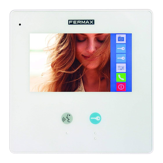
    1. Monitor 1.1 Tasten Mikrofon LCD-Bildschirm Befestigungspunkte Anschlüsse RING Türöffnungstaste Verstärker RING Eigenstartaste 1.2 Funktionen LCD-Bildschirm Zeigt das Videobild der Kamera an der Türstation. Türöffnungstaste Zur Türöffnung drücken. Taste Drücken, um eine Verbindung im Freisprechbetrieb mit dem EIGENSTART Besucher herzustellen. Falls sich der Monitor im Bereitschaftsmodus befi...
  • Seite 57: Tasten Und Funktionen

    2. Türstation Tasten und Funktionen Kamera Camera Lens Verstärker Speaker LEDs Night Light Nacht- beleuchtung Infomodul Nameplate Anruf Call Button Mikrofon Microphone Rainy Cover Schutzblende 90 mm (Regenschutz) 23 mm Beschreibung der Sprechstellen: JP/LK JP/LK 1 2 3 P L S + B U S Anschluss der Haupt-Pins Main Connect Port...
  • Seite 58: Monitorinstallation

    3. Installation 3.1 Monitorinstallation 1. Verwenden Sie die mitgelieferten Schrauben zur Anbringung der Befestigung (im Lieferumfang enthalten). Zur Befestigung sind zwei Schrauben des Typs 4x25 zu verwenden. Die Stecker anschließen, um den Bus zu verbinden. 2. Den Bus richtig (Kabel) am Monitor anschließen (siehe Kapitel 13). Installationsschemata), anschließend den Monitor an der Wandbefestigung anbringen.
  • Seite 59: Etikette Im Infomodul Einlegen

    4. Etikette im Infomodul einlegen Die Kunststoffabdeckung wegnehmen, um den durchsichtigen Teil des Infomoduls zu öffnen, in dem sich die Etiketten befi nden. Etikette einfügen und das Infomodul wieder einfügen. STEP 1 STEP 2 SCHRITT 1 SCHRITT 2 Türstation losschrauben Etikette einlegen Unscrew the screws.
  • Seite 60 5.2 Im Sprechmodus Während einer bestehenden Sprechverbindung mit der Türstation. Name der Türstation. Zeigt die Anrufdauer an. 00:10 Door 6. Anrufannahme 1. Durch Drücken der Ruftaste an der Türstation wird ein Klingelton an der Door 00:10 Türstation und am Monitor ausgelöst und der Bildschirm schaltet sich ein.
  • Seite 61: Lautstärkeeinstellungen

    7. Bildschirm- und Lautstärkeeinstellungen Während des Anrufs oder im Sprechbetrieb mit der Türstation das Symbol drü- cken, um den Bildschirm der Bild- und Toneinstellungen einzublenden. Tür 00:10 Kontrast: Helligkeit: Farbe: Lautstärke: Bildschirmeinstellungen Folgendes kann reguliert werden: Kontrast, Helligkeit, und Farbe. Durch Ändern von Farbe, Helligkeit oder Kontrast ändert sich die Voreinstellung automatisch.
  • Seite 62: Modus Nicht Stören

    9. Modus Nicht stören Das Symbol Nicht stören des Hauptmenüs drücken, um die Funktion Nicht stören aufzurufen. Diese Funktion umfasst vier Optionen: Normal, In 1 Stunde, In 8 Stunden und Immer. Nicht stören Normal Immer Eingenstart Intercom Nicht stören Einstellungen In 1 Stunde In 8 Stunde Hinweis:...
  • Seite 63: Aktivieren/Deaktivieren Der Audiofunktion Des Tastbildschirms

    10.1 Aktivieren/deaktivieren der Audiofunktion des Tastbildschirms Aktivierung/Deaktivierung der Tastentöne am Bildschirm. Einstellungen Hinweis: Das Symbol oder drücken, um die diese Klingelton Option zu aktivieren oder zu deaktivieren. Intercom Klingel Touch 10.2 Programmierung der Eigenstartzeit Einstellung der Einschaltzeit falls die Türstation manuell über den Monitor aktiviert wird.
  • Seite 64: Wiederherstellung Der Werksseitigen Einstellungen

    10.4 Wiederherstellung der werksseitigen Einstellungen Die werksseitigen Einstellungen des Monitors können wiederhergestellt werden. Einstellungen Wiederherstellen Wiederherstellen ? Volumen Zeiteinst Eigenstart 10 min Sprache Wiederherstellen Hinweis: - Das Symbol drücken, und die Meldung: „Werksseitige Einstellungen wiederherstellen?“ be- stätigen. - Das Symbol drücken, um die Wiederherstellung zu starten.
  • Seite 65: Aktivierungszeit Des Türöffners

    11.2 Eingabe des Türöffnertyps und der Aktivierungszeit Türöffnertyp und Funktionsweise: Es gibt zwei Betriebsmodi: 1. Türöffner mit normaler Funktionsweise: Ermöglicht die Türöffnung solange der Türöffner unter Strom steht. 2. Türöffner mit invertierter Funktionsweise: Ermöglicht die Türöffnung solange der Türöffner nicht unter Strom steht. Den Kode 8010 eingeben, falls der Türöffner sich im normalen Betriebsmodus befi...
  • Seite 66 12.1.2 Set mit 2 Linien Klingelton Tür Doorbell Button Switch Klingelton Tür Doorbell Button Switch BUS(IM) BUS(DS) L1 L2 PL S+ S- BUS (M) BUS (DS) Monitor Türstation -11-...
  • Seite 67: Anschluss Des Türöffners

    12.2 Anschluss des Türöffners 12.2.1 Anschluss des Türöffners an das mit dem Set mitgelieferte Netzgerät Hinweis: 1 2 3 Anschluss des Türöffners Die 1 2 3 connect Electronic lock, the jumper position in 2-3. Steckbrücke an der Türstation muss 1. Der installierte Türöffner muss unter bei 1 oder 2 eingesteckt sein.
  • Seite 68: Türöffnungszeit Einstellen

    13. Inbetriebnahme Hinweis: M i t d e r T ü r s t a t i o n ( 1 Ta s t e ) d i e Frontblende entfernen, um die Taste B zu lokalisieren. 13.1 Türöffnungszeit einstellen Die Stromversorgung vor Im Programmiermodus die Taste „A“...
  • Seite 69: Bestätigung Des Ruftons An Der Türstation Einstellen

    13.2 Bestätigung des Ruftons an der Türstation einstellen Die Stromversorgung vor Im Programmiermodus die Taste Ablauf von fünf Sekunden „B“ drei Sekunden lang gedrückt wiederherstellen. Dann die halten. Man gelangt in den Taste „B“ drei Sekunden lang Bestätigungsmodus des Klingeltons. gedrückt halten.
  • Seite 70: Verkabelungsanforderungen

    14. Verkabelungsanforderungen Eindrahtschema monitor monitor BUS(IM) BUS(DS) Maximale Entfernungen gemäß verwendetem Kabel Querschn./Abstände Verdrilltes Kabel 2 x 0,75 mm Verdrilltes Kabel 2 x 1 mm -15-...
  • Seite 71: Technische Eigenschaften

    15. Technische Eigenschaften ● Netzgerät: 26 VDC +/- 2 (Türstation) 20 ~ 28 VDC (Monitor) ● Stromverbrauch: Bereitschaftsmodus 6.5mA; aktiviert 180mA (Monitor) Bereitschaftsmodus 33 mA; Betriebsmodus 110 mA (Türstation) ● Monitorbildschirm: Digitaler 4.3“ TFT-Farbbildschirm ● Display-Aufl ösung: 480 (R, G, B) x 272 Pixel ●...
  • Seite 72 Technische Veröffentlichung zu Informationszwecken; Herausgeber: FERMAX ELECTRONICA. FERMAX behält sich das Recht vor, den Inhalt dieses Dokuments sowie die technischen Eigenschaften der erwähnten Produkte ohne vorherige Ankündigung zu ändern, um dadurch den ständigen Weiterentwicklungen und den damit in Verbindung stehenden Verbesserungen Rechnung zu tragen.
  • Seite 73 KIT VIDEO WAY SLIM 1-2 L...
  • Seite 74 1. Monitor 1.1 Botões Microfone Ecrã LCD Pontos de fi xação Conectores RING Botão de Altifalante Botão LIGAÇÃO trincos AUTOMÁTICA RING 1.2 Funções Ecrã LCD Mostra a imagem de vídeo da câmara da botoneira Botão de trinco Premir para abrir a porta. Botão LIGAÇÃO Premir para comunicar com o visitante em modo mãos livres.
  • Seite 75: Descrição Dos Terminais

    2. Botoneira Botões e funções Câmara Camera Lens Altifalante Speaker LEDs de iluminação Night Light noturna Placa de identifi cação Nameplate Chamada Call Button Microfone Microphone Viseira Rainy Cover (proteção da 90 mm chuva) 23 mm Descrição dos terminais JP/LK JP/LK 1 2 3 P L S +...
  • Seite 76: Instalação Do Monitor

    3. Instalação 3.1 Instalação do monitor 1. Utilize os parafusos para fixar o suporte de montagem na caixa de montagem (acessórios incluídos no suporte). São necessários dois parafusos para a fi xação do suporte. Ligar os conectores para a ligação do bus. 2.
  • Seite 77: Menu Principal

    4. Colocar a etiqueta no porta-cartões Retire a cobertura de plástico, para abrir a parte transparente do porta-cartões onde se situará a etiqueta, aplique a etiqueta e deixe novamente o porta-cartões na sua posição original. STEP 1 STEP 2 PASSO 1 PASSO 2 Desaparafusar a botoneira.
  • Seite 78 5.2 Em comunicação Enquanto se comunica com a botoneira de rua. Mostra o tempo de chamada. Nome da botoneira 00:10 Door 6. Respondendo a uma chamada 1. Ao premir o botão de CHAMADA na botoneira de rua, ouve-se um som de Door 00:10 chamada tanto na botoneira da rua como...
  • Seite 79: Função Intercom

    7. Ajustes do ecrã e volume Durante a chamada, ou em comunicação com a botoneira, premir o ícone para visualizar o ecrã de ajuste de vídeo e volume. Door 00:10 Contraste: Brilho: Cor: Volume: Ajustes do ecrã É possível selecionar o Contraste, o Brilho e a Cor. Quando se modifica a Cor, o Brilho ou o Contraste, a cena muda automaticamente.
  • Seite 80: Função Não Incomodar

    9. Função Não incomodar Premir o ícone Não incomodar do menu principal para aceder à função Não incomodar. Esta função tem 4 opções: Normal, Em 1 hora, Em 8 horas e Sempre. Não Incomodar Normal Sempre Ligacão Intercom Não Defi nições Automática Incomodar Em 1 hora...
  • Seite 81: Seleção Do Idioma

    10.1 Ativar/Desativar o áudio do ecrã tátil Ativa/desativa o som de toque no ecrã. Defi nições Nota: Tom de toque Tocar nos ícones no ecrã, para ativar/ Intercom desativar esta opção. Campainha Touch 10.2 Programação do tempo de ligação automática Ajuste do tempo ligado ao ativar a botoneira de rua manualmente a partir do monitor.
  • Seite 82 10.4 Restaurar para valores de fábrica Está disponível a possibilidade de restaurar os parâmetros do monitor para valores de fábrica. Restaurar Defi nições Restaurar defi nições? Volumen Tempo Ligacão Automática 10min Idioma Restaurar Nota: - Tocando no ícone , será pedida uma confi rmação através da mensagem “Restaurar predefi nição?”. - Tocar no ícone para iniciar o restauro.
  • Seite 83: Esquema De Instalação

    11.2 Como introduzir o tipo de trinco e o tempo de ativação Tipo de trinco e funcionamento: Existem dois modos de funcionamento: 1. Trinco de Funcionamento Normal: Permite a abertura da porta durante o tempo em que o trinco recebe alimentação. 2.
  • Seite 84 12.1.2 Kit de 2 linhas Campainha da porta Doorbell Button Switch Campainha da porta Doorbell Button Switch BUS(IM) BUS(DS) L1 L2 PL S+ S- BUS (M) BUS (DS) Monitor Botoneira -11-...
  • Seite 85 12.2 Ligação do trinco 12.2.1 Ligação do trinco com a fonte incluída no kit 1 2 3 Nota: 1 2 3 Ligação do trinco. A posição da connect Electronic lock, the jumper position in 2-3. ponte na botoneira deve ser 1-2. 1.
  • Seite 86: Colocação Em Funcionamento

    13. Colocação em funcionamento Nota: Com uma botoneira de 1 botão, abrir a cobertura frontal para procurar o botão B. 13.1 Ajustar o tempo do trinco Fornecer alimentação Estando no modo de programação, e, antes de passarem 5 premir o botão "A" durante 3 segundos, premir o botão segundos.
  • Seite 87 13.2 Ajustar a confi rmação do som de chamada na botoneira Fornecer alimentação Estando no modo de programação, e, antes de passarem 5 premir o botão "B" durante 3 segundos, premir o botão segundos. Acede-se ao modo de "B" durante 3 segundos. confi...
  • Seite 88 14. Requisitos da cablagem Esquema unifi lar monitor monitor BUS(IM) BUS(DS) Distâncias máximas conforme o cabo utilizado Secções/Distâncias Cabo trançado 2 x 0,75 mm Cabo trançado 2 x 1 mm -15-...
  • Seite 89 15. Características Técnicas ● Alimentação: 26 VDC +/- 2 (botoneira) 20~28 VDC (monitor) ● Consumo: Em repouso: 6.5mA; Ativado: 180mA (monitor) Em repouso: 33 mA; Ativado: 110 mA (botoneira) ● Ecrã do monitor: TFT digital de 4,3 polegadas a cores ●...
  • Seite 90 Publicação técnica de carácter informativo editada pela FERMAX ELECTRONICA. A FERMAX, na sua política de constante melhoria, reserva-se o direito de modificar o conteúdo deste documento, assim como as características dos produtos que nele são referidos, a qualquer momento e sem aviso prévio.

Inhaltsverzeichnis