Frese SIGMA Compact Montageanleitung
Frese SIGMA Compact
Montagevejledning
DK
Montageanleitung
DE
Mounting instructions
EN
Danmark · Tlf. +45 58 56 00 00
Deutschland · Tel. +49 (0)241 475 82 333
UK · Tel. +44 (0)1704 896012
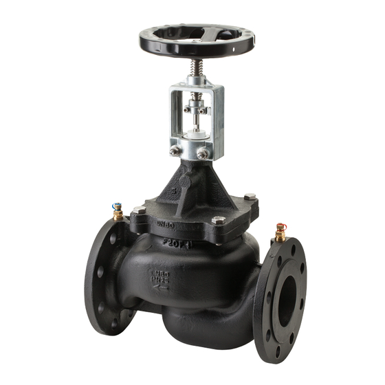
Produktbeskrivelse: Frese SIGMA Compact stilbar dynamisk
DK
reguleringsventil. (Se technote).
Produktbeschreibung: Frese
DE
dynamische Volumenstromregler. (Siehe technote)
Product Description: Frese SIGMA Compact externally
EN
adjustable dynamic balancing valve. (See technote)
FIG 1
FIG 1 Installation: Frese SIGMA Compact kan installeres i enten
DK
fremløb eller retur. Det anbefales, at man installerer snavssamlere
og kuglehaner.
FIG 1 Installation: Frese SIGMA Compact wird im Vor- oder
DE
Rücklauf montiert. Schmutzfänger und Absperrkugelhähne
werden empfohlen.
FIG 1 Installation: Frese SIGMA Compact can be mounted in
EN
either the supply or the return line. Installation of strainers and
isolation ball valves are recommended.
Sikkerhedsinstruktion: Fabrikanten forholder sig ikke ansvarlig
DK
for nogen form for skade forvoldt ved anden brug end den
angivede applikation. Sådanne risici forbeholdes udelukkende
brugeren. Det er vigtigt at overholde montagevejledningen for
at sikre korrekt anvendelse af ventilen.
Sicherheitsanleitung: Der Hersteller übernimmt keine Haftung
DE
für Schäden, die aus nicht verwendungszweck-bezogener
Handhabung resultieren. Diese Risiken liegen ausschliesslich bei
dem Anwender. Die Berücksichtigung dieser Montageanleitung
ist als Teil des Verwendungszweckes des Ventiles anzusehen.
Safety Instructions: The manufacturer is not liable for any
EN
damage resulting from use other than in the designated
application. Such risk lies entirely with the user. Observance
of the mounting instructions is considered as part of the valve
designated use.
DN50-DN150
SIGMA
Compact
stellbare
www.frese.eu
FIG 2
FIG 2: Indstilling af flow ifølge grafer eller Frese's APP .
FIG 2: Voreinstellung nach Volumenstromdiagrammen oder der
Frese App.
FIG 2: Flow pre-setting using the graphs or the Frese APP for the
valve dimension in question.
FIG 3
FIG 3: Indstillingshåndtag monteres på ventil.
FIG 3: Handrat wird auf dem Ventil montiert.
FIG 3: Hand wheel is mounted on the valve neck
FIG 4
FIG 4: Ventilspindel fastgøres til indstillingshåndtag
FIG 4: Ventilstössel wird mit dem Handrat montiert.
FIG 4: Valve spindle is lock to the hand wheel.

Verwandte Anleitungen für Frese SIGMA Compact


Inhaltszusammenfassung für Frese SIGMA Compact
- Seite 1 FIG 2: Voreinstellung nach Volumenstromdiagrammen oder der FIG 1 Frese App. FIG 2: Flow pre-setting using the graphs or the Frese APP for the valve dimension in question. FIG 3 FIG 1 Installation: Frese SIGMA Compact kan installeres i enten fremløb eller retur.
- Seite 2 - 2 - Frese SIGMA Compact . Low Flow DN50 Frese SIGMA Compact . High Flow DN50 Flow min. Δp kPa Flow min. Δp kPa 6.67 24.0 4.17 15.0 6.11 22.0 5.56 20.0 5.00 18.0 4.44 16.0 2.78 10.0 3.89 14.0...
- Seite 3 - 3 - Frese SIGMA Compact . Low Flow DN100 Frese SIGMA Compact . High Flow DN100 Flow Flow min. Δp kPa min. Δp kPa 19.44 70.0 25.00 90.0 22.22 80.0 16.67 60.0 19.44 70.0 13.89 50.0 16.67 60.0 11.11 40.0...