Inhaltsverzeichnis
Werbung
Verfügbare Sprachen
Verfügbare Sprachen
Quicklinks
Werbung
Kapitel
Inhaltsverzeichnis

Verwandte Anleitungen für Fluke Networks MicroNetBlink


Inhaltszusammenfassung für Fluke Networks MicroNetBlink
- Seite 1 M I C R O T O O L S ICRO LINK ™...
- Seite 2 MicroProbe User Guide Manuel Utilisateur Benutzer Handbuch Manuale per l'utente Guía del Usuario Manual do Utilizador 2947-4511-01 Rev. 01 11/01 © 2001 Fluke Networks, Inc. All rights reserved. Printed in USA. All product names are trademarks of their respective companies.
-
Seite 4: Inhaltsverzeichnis
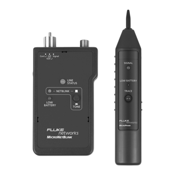
ROBE tone amplifier and an LED indicator that detects audible frequency tones for accurate tracing and identification of wires. Contents MicroNetBlink Features: ..........3 MicroProbe Features ..........3 Battery ................ 4 High Voltage Protection ..........4 MicroNetBlink Tests ............ 5 Flashing the Hub Light Status ........ - Seite 5 Ring/Tip Polarity Test LED Netblink/ Netblink Tone Button Battery RJ11Connector for Continuity Test and Trace Button Tip/Ring Signal. Red and Black Alligator clips for Continuity and Voltage Check. RJ45 Connector for flashing of Hublight and Tone Tracing. MicroNetBlink / MicroProbe...
-
Seite 6: Micronetblink Features
• Locates RJ45 jacks in wiring systems • Adjustable volume level control and LED indicator for noisy work environments • Power switch prevents battery drain • Works with all tone generators including MICROSCANNER PRO, MICROMAPPER, MICRONETBLINK • Low battery indicator ENGLISH - 3... -
Seite 7: Battery
LINK voltage conditions that arise from normal telephony applications such as 48 VDC at less than 80 ma or 24 VAC used to power many keysets. Tests cannot be performed when hazard conditions exist on the inputs. MicroNetBlink / MicroProbe... -
Seite 8: Micronetblink Tests
Tests ICRO LINK Flashing the Hub Light Status 1. Set the toggle switch to the Signal position. 2. Plug the 8-position cable (RJ45) into the jack to be tested. 3. Verify that the button on the face of the in the NETBLINK position. ICRO LINK IS 4. -
Seite 9: Identifying Telephone Line Polarity
GREEN (DIM) indicates a correct wired telephone circuit already in use or off-hook RED indicates a reversed polarity phone circuit 3. Use a second phone line to dial the number under test. RED and GREEN (rapidly flashing) indicates a ringing signal. MicroNetBlink / MicroProbe... -
Seite 10: Testing For Low Voltage
Cont ü position. CAUTION: Telephone circuit voltages can be hazardous, never touch the metal of the test leads while the MicroNetBlink is attached to a telephone line. Testing for Low Voltage CAUTION: MicroNetBlink is designed for checking low voltage (less than 24 Volts DC or AC only). -
Seite 11: Testing Continuity
• To test un-terminated coaxial cables connect the red test lead to the outer shield and the black test lead to the center conductor, or connect the red test lead to the outer shield and the black test lead to the ground. MicroNetBlink / MicroProbe... -
Seite 12: Appendix A
• To test terminated coaxial cables, connect the red test lead to the connector housing and the black test lead to center pin, or connect the red test lead to the connector housing and the black test lead to the ground. Appendix A ICRO LINK... - Seite 13 • Pen-style casing • Special inductive plastic tip • One push-button TRACE switch • One battery low LED indicator • One speaker and one LED for signal detection • One rotary volume level switch MicroNetBlink / MicroProbe...
- Seite 14 Table des matières MicroNetBlink et MicroProbe ........2 Fonctionnalités de MicroNetBlink ........ 3 Fonctionnalités de MicroProbe ........3 Pile ................4 Protection contre le risque de surtension ....
- Seite 15 Bouton jonction. Trace Pinces crocodiles rouges et noires pour le test de continuité et le contrôle de tension. Connecteur RJ-45 pour le clignotement du voyant de hub et le suivi de la tonalité. MicroNetBlink / MicroProbe...
-
Seite 16: Fonctionnalités De Micronetblink
• Réglage du volume sonore et présence d’un témoin lumineux pour les environnements de travail bruyants. • Interrupteur d’alimentation permettant d’empêcher l’épuisement de la batterie. • Compatible avec tous les générateurs de tonalités, dont MICROSCANNER PRO, MICROMAPPER, MICRONETBLINK • Témoin de batterie faible FRANÇAIS - 3... -
Seite 17: Pile
48 Vcc (pour moins de 80 mA) ou de 24 Vca qui alimente de nombreux appareils à clavier. Aucun test ne peut être exécuté en cas d’instabilité majeure de l’alimenta- tion. MicroNetBlink / MicroProbe... -
Seite 18: Tests Micronetblink
Tests M ICRO LINK Clignotement du voyant d’état du hub 1. Placez le commutateur à bascule en position Signal. 2. Branchez le câble à 8 positions (RJ-45) sur la prise à tester. 3. Assurez-vous que le bouton situé à l’avant de l’unité... -
Seite 19: Identification De La Polarité De La Ligne Téléphonique
Un voyant VERT (PÂLE) indique un circuit téléphonique correctement câblé en position de travail (combiné décroché). Un voyant ROUGE indique un circuit téléphonique à polarité inversée. 3. Utilisez une seconde ligne téléphonique pour composer le numéro à tester. MicroNetBlink / MicroProbe... -
Seite 20: Détection De Basse Tension
Cont ü. ATTENTION : les tensions de circuit téléphonique peuvent être dangereuses. Ne touchez pas la partie métallique des fils de test lorsque MicroNetBlink est connecté à une ligne téléphonique. Détection de basse tension ATTENTION : MicroNetBlink est conçu pour contrôler des basses tensions (moins de 24 Volts... -
Seite 21: Test De La Continuité
à la broche centrale. Une autre solution consiste à connecter le fil de test rouge au boîtier du connecteur et à relier le fil de test noir à la terre. MicroNetBlink / MicroProbe... -
Seite 22: Annexe A
Annexe A ICRO LINK • Dimensions : 115 mm x 63 mm x 26 mm • Poids : 19 g • Alimentation : pile alcaline CC de 9 V (non fournie) • +/- 30 cm de fil de test noir et rouge à pinces crocodiles pour les tests de continuité... - Seite 23 • Etui de type porte-stylo • Pointe plastique inductive spéciale • Un bouton TRACE • Un voyant de batterie faible • Un haut-parleur et un voyant pour la détection du signal • Un bouton de réglage du volume MicroNetBlink / MicroProbe...
-
Seite 24: Micro Net Blink Und M
ROBE und eine LED-Anzeige, die hörbare Töne zur ge- nauen Verfolgung und Bestimmung von Kabeln er- kennt. Inhalt Funktionen von MicroNetBlink ........3 Funktionen von MicroProbe ........3 Batterie ................ 4 Überspannungsschutz ..........4 MicroNetBlink-Tests ............ 5 Blinkanzeige für Hub-Status ........5 Aussenden eines Signaltons ........ - Seite 25 Ring/Tip- Signalton- Polaritäts- verfolgung prüfung Netblink-LED Netblink-/ Signal- tontaste Batterie LED RJ11Connector for Continuity Test and Taste zur Tip/Ring Signal. Kabel- verfolgung Rote und schwarze Krokodilklemmen für Kontinuitäts- und Spannungsprüfung RJ45-Anschluss für blinkende Hub- Anzeige und Signaltonverfolgung MicroNetBlink / MicroProbe...
-
Seite 26: Funktionen Von Micronetblink
• Erkennung von RJ45-Buchsen in Verdrahtungssystemen • Lautstärkeregelung und LED-Anzeige für laute Arbeitsum- gebungen • Netzschalter zur Vermeidung der vollständigen Batterie- entladung • Arbeitet mit allen Signaltongeräten, einschließlich MICROSCANNER PRO, MICROMAPPER und MICRONETBLINK • Anzeige für niedrige Batterieladung Deutsch - 3... -
Seite 27: Batterie
Das M ist gegen Überspannung ICRO LINK geschützt, die bei aktiven Standard-Telefonleitun- gen mit 48 V GS (bei weniger als 80 mA) bzw. 24 V WS auftreten kann. Bei überhöhter Eingangs- spannung kann kein Test durchgeführt werden. MicroNetBlink / MicroProbe... -
Seite 28: Micronetblink-Tests
-Tests ICRO LINK Blinkanzeige für Hub-Status 1. Stellen Sie den Kippschalter auf die Position Signal. 2. Schließen Sie das 8-adrige Kabel (RJ45) an der zu testenden Buchse an. 3. Prüfen Sie, ob sich die Taste vorne am in der Position NETBLINK ICRO LINK befindet. -
Seite 29: Erkennen Der Telefonleitungspolarität
Sie die Prüfleitung mit der roten Krokodilklemme an RING (-) und die Prüfleitung mit der schwarzen Krokodilklemme an TIP (+) an. Die LED-Anzeige leuchtet auf: GRÜN bedeutet, dass die Telefonleitung richtig verdrahtet ist, wobei der Telefonhörer aufgelegt ist. MicroNetBlink / MicroProbe... -
Seite 30: Prüfen Auf Niederspannung
ü befindet. ACHTUNG: Die in Telefonleitungen vorhandene Spannung kann gefährlich sein. Daher sollten Sie die Metallteile der Prüfleitungen beim Anschluss des MicroNetBlink an eine Telefonleitung unter keinen Umständen berühren. Prüfen auf Niederspannung ACHTUNG: MicroNetBlink ist zur Niederspan- nungsprüfung geeignet (weniger als 24 Volt GS oder nur WS). -
Seite 31: Prüfen Der Kontinuität
Leitung an. Die LED-Anzeige leuchtet auf: GRÜN zeigt einen niederohmigen Pfad von der ROTEN PRÜFLEITUNG (+) zur SCHWAR- ZEN PRÜFLEITUNG (-) an. GRÜN (HELLGRÜN) zeigt einen hochohmigen Pfad an. OFF (AUS) zeigt einen offenen Stromkreis an. MicroNetBlink / MicroProbe... -
Seite 32: Prüfen Der Kontinuität Mittels Signalton
Prüfen der Kontinuität mittels Signalton 1. Stellen Sie den Kippschalter auf die Position Signal. 2. Schließen Sie die Prüfleitungen an das zu prüfende Paar an. 3. Bei Verwendung eines Handapparats oder einer Sprechgarnitur am anderen Ende berühren Sie das (die) Drahtende(n) mit der (den) Klemme(n). - Seite 33 • Gewicht: 16 g • Stromversorgung: 9-V-Alkalibatterie, GS (nicht im Lieferumfang enthalten) • Etui • Spezielle induktive Kunststoffspitze • Ein Druckschalter TRACE (Verfolgung) • Eine LED-Anzeige für niedrige Batterieladung • Ein Lautsprecher und eine LED-Anzeige für Signaltoner- kennung MicroNetBlink / MicroProbe...
- Seite 34 LED in grado di rilevare segnali acustici a frequenza per l’accurata tracciatura e identificazione dei cavi. Indice MicroNetBlink e MicroProbe ........... 2 Funzionalità di MicroNetBlink ........3 Funzionalità di MicroProbe ..........3 Batteria ................4 Protezione da alta tensione ..........
- Seite 35 Connettore RJ11 per test di continuità e Pulsante segnale Tip/Ring Traccia Morsetti a coccodrillo rossi e neri per la verifica di continuità e tensione Connettore RJ45 per lampeggiamento dell’indicatore hub e tracciatura con segnale acustico MicroNetBlink / MicroProbe...
-
Seite 36: Funzionalità Di Micronetblink
• Controllo di regolazione volume e indicatore LED per ambienti di lavoro rumorosi • L’interruttore di alimentazione evita che le batterie si scarichino • Opera con tutti i generatori di segnali acustici, compresi MICROSCANNER PRO, MICROMAPPER, MICRONETBLINK • Indicatore batteria scarica ITALIANO - 3... -
Seite 37: Batteria
(48 V c.c. a meno di 80 mA) o dalla potenza di 24 V c.a. utilizzata da molti apparecchi telefonici. Non è possibile effettuare test in presenza di condizioni di pericolo nella tensione d’ingresso. MicroNetBlink / MicroProbe... -
Seite 38: Test Di Micronetblink
Test di ICRO LINK Lampeggiamento dell’indicatore di stato 1. Impostare il commutatore nella posizione Signal. 2. Collegare il cavo a 8 posizioni (RJ45) nel jack da testare. 3. Verificare che il pulsante sul lato anteriore di M sia in posizione NETBLINK. ICRO LINK 4. -
Seite 39: Identificazione Della Polarità Della Linea Telefonica
RING (-) e quello nero con estremità a coccodrillo a TIP (+). L’indicatore LED si accende: VERDE indica un circuito telefonico cablato corretto e agganciato MicroNetBlink / MicroProbe... -
Seite 40: Test Bassa Tensione
è nella posizione Cont ü. ATTENZIONE: Le tensioni dei circuiti telefonici possono essere pericolose; non toccare mai il metallo dei cavi test se MicroNetBlink è collegato a una linea telefonica. Test bassa tensione ATTENZIONE: MicroNetBlink è concepito per la verifica delle basse tensioni (solo inferiori a 24 Volt c.c. -
Seite 41: Test Di Continuità
1. Impostare il commutatore nella posizione Signal. 2. Collegare i cavi test alla coppia da testare. 3. Utilizzando all’estremità remota un normale ricevitore telefonico o una cuffia, toccare la(e) estremità dei fili con il(i) morsetto(i) del(i) cavo(i). MicroNetBlink / MicroProbe... -
Seite 42: Test Cavi Coassiali
La ricezione del segnale acustico è un’indicazione di continuità. Tutti i test di cui sopra sono validi esclusivamente per spinotti modulari per la linea 1 (cavi rossi e verdi). Test cavi coassiali • Per testare cavi coassiali senza terminazione, collegare il cavo test rosso alla schermatura esterna e il cavo test nero al conduttore centrale oppure collegare il cavo test rosso alla schermatura esterna e il cavo test nero alla... -
Seite 43: Appendice A
• Speciale ago induttivo in plastica • Un commutatore di traccia a pulsante • Un indicatore LED di batteria scarica • Un altoparlante e un LED per il rilevamento del segnale • Un commutatore girevole per il livello del volume MicroNetBlink / MicroProbe... - Seite 44 Contenido MicroNetBlink y MicroProbe ............2 Características de MicroNetBlink ........... 3 Características de MicroProbe ............3 Batería .................... 4 Protección contra sobretensión ............4 Pruebas con MicroNetBlink ............
- Seite 45 Pinzas de cocodrilo en rojo y negro para comprobar la tensión y la continuidad. Conector RJ45 para el parpadeo de la luz del nodo y el seguimiento del tono. MicroNetBlink / MicroProbe...
-
Seite 46: Características De Micronetblink
• Control de nivel de volumen regulable e indicador LED para ambientes de trabajo ruidosos • El conmutador de alimentación evita que la batería se descargue • Opera con cualquier generador de señal acústica, incluidos MICROSCANNER PRO, MICROMAPPER, MICRONETBLINK • Indicador de batería baja ESPAÑOL - 3... -
Seite 47: Batería
48 V de CC a menos de 80 mA o 24 V de CA para la alimentación de aparatos telefónicos. Cuando existen condiciones de peligro en las entradas, no se deben realizar pruebas. MicroNetBlink / MicroProbe... -
Seite 48: Pruebas Con Micronetblink
Pruebas con M ICRO LINK Parpadeo de la luz de estado del nodo 1. Seleccione con el conmutador la posición Signal (Señal) 2. Enchufe el cable de 8 posiciones (RJ45) en el jack que se va a comprobar. 3. Compruebe que el botón de la parte delantera de M se encuentra en... -
Seite 49: Identificación De La Polaridad De La Línea Telefónica
(+). Se encenderá el indicador LED: En VERDE indica que se trata de un circuito telefónico con cableado correcto que está desocupado. En VERDE (tenue) indica que es un circuito MicroNetBlink / MicroProbe... -
Seite 50: Comprobación De Bajo Voltaje
Cont ü . PRECAUCIONES: No toque nunca el metal de los conductores de pruebas cuando MicroNetBlink se encuentra conectado a una línea telefónica. El voltaje de los circuitos telefónicos puede ser peligroso. Comprobación de bajo voltaje PRECAUCIONES: MicroNetBlink está... -
Seite 51: Comprobación De La Continuidad
1. Seleccione con el conmutador la posición Signal (Señal). 2. Conecte los conductores de pruebas al par que se quiere comprobar. 3. Toque los extremos de los conductores con los conductores de pinza, empleando el microteléfono o el auricular en el extremo remoto. MicroNetBlink / MicroProbe... -
Seite 52: Pruebas Coaxiales
La recepción del tono indica la continuidad. Todas las pruebas anteriormente mencionadas pueden aplicarse a los conectores modulares de sólo una línea (conductores rojos y verdes). Pruebas coaxiales • Para comprobar cables coaxiales sin termina- ción, conecte el conductor de prueba rojo al blindaje externo y el conductor de prueba negro al conductor central, o bien conecte el conductor de prueba rojo al blindaje externo y... -
Seite 53: Appendix A
• Alimentación eléctrica: Pila alcalina de 9V de CC (no incluida) • Funda protectora • Punta especial de plástico inductivo • Pulsador de rastreo (Trace) • Indicador LED de batería baja • Altavoz y LED de detección de señales • Control de volumen MicroNetBlink / MicroProbe... - Seite 54 Índice MicroNetBlink e MicroProbe ........2 Características do MicroNetBlink ........ 3 Características do MicroProbe ........3 Bateria ................. 4 Proteção Contra Alta Tensão ........4 Testes do MicroNetBlink ..........
-
Seite 55: Micronetblink E Microprobe
Conector RJ11 para Teste de Continuidade e Sinal de Botão de Ponta/Toque. Rastreamento Garras “Jacaré” Vermelha e Preta para Verificação de Tensão e Continuidade. Conector RJ45 para acendimento piscante da Luz de Hub e para Acompanha- mento de Sinal Acústico. MicroNetBlink / MicroProbe... -
Seite 56: Características Do Microprobe
• Controle ajustável de nível de volume e indicador luminoso para ambientes de trabalho ruidosos • Chave liga/desliga para evitar descarga da bateria • Funciona com todos os geradores de sinal acústico, entre eles MICROSCANNER PRO, MICROMAPPER, MICRONETBLINK • Indicador de carga baixa de bateria PORTUGUÊS - 3... -
Seite 57: Bateria
48 VCC a menos de 80 mA, ou 24 VCA, utilizadas para alimentar muitos conjuntos telefônicos. Não é possível realizar testes quando houver condições de perigo nas entradas. MicroNetBlink / MicroProbe... -
Seite 58: Testes Do Micronetblink
Testes do M ICRO LINK Piscando a Luz de Estado de Hub 1. Posicione a chave alternada em Signal. 2. Conecte o cabo RJ45 de 8 posições ao conector a ser testado. 3. Verifique se o botão frontal do está na posição NETBLINK. ICRO LINK 4. -
Seite 59: Identificando A Polaridade De Linhas Telefônicas
VERMELHO indica um circuito telefônico com polarida- de i nvaertida 3. Use uma outra linha telefônica para discar para chamar o número que está sendo testado. VERDE e VERMELHO (piscando rapidamente) indica um sinal de toque. MicroNetBlink / MicroProbe... -
Seite 60: Testes De Baixa Tensão
ICRO LINK telefônica. Testes de Baixa Tensão CUIDADO: O MicroNetBlink foi projetado para verificar baixas tensões (inferiores a 24 Volts CC ou CA apenas). Não o conecte a nenhum circuito de alta tensão! 1. Coloque a chave alternada na posição Off/ Volt ü. -
Seite 61: Testes De Continuidade Utilizando Sinais Acústicos
MicroNetBlink / MicroProbe... -
Seite 62: Apêndice A
Apêndice A ICRO LINK • Dimensões: 4,53" x 2,49" x 1,03" 115mm x 63mm x 26mm • Peso: 19g • Alimentação: bateria alcalina de 9VCC (não inclusa) • 1 pé (304,8 mm) de fios com pontas de teste jacaré vermelha e preta, para testes de tensão e continuidade •... - Seite 63 MicroNetBlink / MicroProbe...
- Seite 64 LIMITED WARRANTY & LIMITATION OF LIABILITY Each Fluke Networks product is warranted to be free from defects in material and workmanship under normal use and service. The warranty period is one year and begins on the date of purchase. Parts, accessories, product repairs and services are warranted for 90 days.
- Seite 65 Everett, WA 98206-0777 6-01 Registration Registering your product with Fluke Networks gives you access to valuable information on product updates, troubleshooting tips, and other support services. To register, fill out and return the postage- paid card provided, or fill out the online registration form on the Fluke Networks website.
- Seite 66 M I C R O T O O L S...