Werbung
Quicklinks
Fig. 2
Fig. 3.1
d
Schraffierte Fläche an den Sollbruchstellen
(gestrichelte Linie) vorsichtig heraustrennen.
Fig. 3
Sonderserie
Da die Sonderserie einseitig mit einer geschlossenen Schürze d ausgestattet ist, muss bei beidseitigem
Kupplungsbetrieb das Teilstück an den vorgesehenen Sollbruchstellen (Fig. 3.1) entfernt werden. Richtfeder in
Drehgestellblende einlegen, Klupplungsadapter durch Einsetzen des Splints am Drehgestell befestigen und
PROFI-Kupplung einstecken (Fig. 3).
9426/27
An der schraffierten Stelle kann der Schaltmagnet 9426/27 eingebaut werden (Fig. 4). Ersatzhaftreifen: 54 4006
Ölen: Geölt werden Motor und Getriebe nur an den gekennzeichneten Lagerstellen (Fig. 4, 6 und 7).
Nur FLEISCHMANN-ÖL 6599 verwenden. Nur ein kleiner Tropfen pro Schmierstelle (
Überölung. Zur Dosierung die in der Verschlusskappe der Ölflasche angebrachte Nadel verwenden.
Stromzufuhr über das Gleis:
Schlitz des Schalters in Fahrtrich-
tung (Lieferzustand).
Stromzufuhr über Oberleitung:
Schlitz des Schalters quer zur
Fahrtrichtung (Fig. 2).
a
1-2
Öffnen der Lok: Ein Öffnen der Lok ist nur zum Lampentausch und zum Einbau eines digitalen Empfängerbausteins
erforderlich. Schrauben a
1-2
Ersatzglühlampe: 6530 · Ersatzglühlampe für Maschinenraumbeleuchtung: 9530 (7 4375/6)
Einbau eines digitalen Empfängerbausteins: Auf der schraffierten Fläche kann ein TWIN-DECODER 6847/DCC-
DECODER 6876 mit 6-poligem Stecker (NEM 651) geklebt werden. Beim Einbau bitte die Betriebsanleitung des jeweili-
gen DECODERs beachten (Fig. 5).
d
Ersatz-
schleifkohlen: 6519
Fig. 4
), sonst
b
, b und c
entfernen und Lokgehäuse nach oben abnehmen (Fig. 5).
1-2
Fig. 6
ACHTUNG:
Vor Decodereinbau müssen die
Lötstellen der Steckplatine und
der Metallring des Motors (z. B.
durch Klebepad) elektrisch von-
einander isoliert werden.
Fig. 5
1. In Pfeilrichtung abziehen
Steck-Tauschkupplung
6511
c
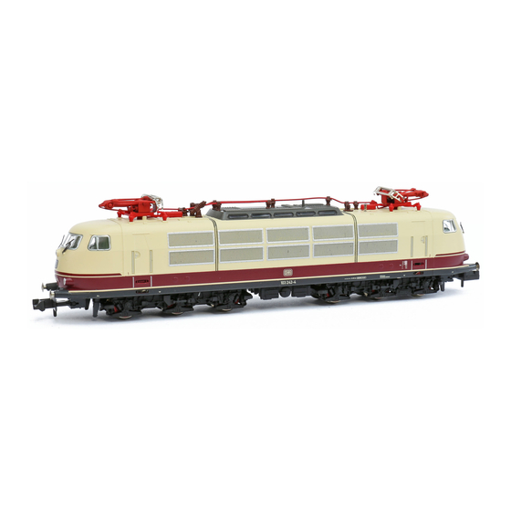
Class 103 with variants
1-2
The German Federal Railway (DB) developed the in those years fastest and most powerful Co-Co electric loco BR 103 especially for
fast IC and TEE trains. From the introduction of the first four prototypes, up to 1977, 145 locos of this series have been manufactured
by Henschel and Siemens. With a power rating ov 7100 kW and a frictional loading of 114 Mp these locos can travel as fast as 200
km/h. During their years of service small alterations have been made to the bodies, and various types of pantograph have been added
(Fig.1).
Current pick-up from the track: The slot of the switch points in the direction of travel (as delivered) (Fig. 2).
Current pick-up from the overhead: The slot of the switch points across the body (Fig. 2).
Limited Edition Series: Because the limited edition series is fitted with closed in skirts d, the small pre-scored part (Fig. 3.1) must
be removed in order for the coupling operation at each end to operate. First of all lay the coupling spring in position followed by the
coupling adapter, fixing the splint onto the bogie. Insert the Profi-coupling into the coupling adapter (Fig. 3).
The indicated point can be used for locating the switching magnet 9426 (Fig. 4). Spare traction tyres: 54 4006
Lubrication: The motor and gear-box need only be lightly oiled at the bearing points marked (Fig. 4, 6 and 7). Only use FLEISCH-
MANN-oil 6599. Only put a tiny drop in each place (
of the oil bottle for your use.
Opening the loco: Opening the loco is only necessary to replace the bulbs and install a digital receiver. Remove screws a
c
. Lift the loco body gentle upwards (Fig. 5). Spare bulb: 6530 + 9530 (7 4375/6)
1-2
Installing the digital decoder: A 6-pole TWIN-DECODER 6847 (NEM 651)/DCC DECODER 6876 can be glued onto the cross-
hatched surface (Fig. 5). Please consult the instructions included with the respective DECODER for fitting advice.
Spare brushes: 6519 (Fig. 7).
ATTENTION: Before installing the decoder, the soldered areas on the plug printed circuit board and the metal ring of the motor must
be electrically isolated from each other (i.e. by using the sticky pad) (Fig. 7).
Exchange coupling: Clip exchange coupling: 6511 · FLEISCHMANN-PROFI Clip coupling: 6515. 1. Pull off in direction of arrow. ·
2. Insert exchange coupling in direction of arrow until clipped in position.
Série 103 avec variantes
Les plus rapides et les plus puissantes locomotives électriques Co'Co' de la série 103 ont été construites pour la Deutsche
Bundesbahn (DB). Elles sont destinées à remorquer des trains IC et TEE. Après la réalisation de 4 prototypes, les firmes Henschel et
Siemens ont construit, jusqu'en 1977, une série de 145 locomotives. Avec une consommation de 7100 kW et une puissance de 114 Mp
Fig. 7
elles peuvent atteindre une vitesse maximum de 200 km/h. Au cours de années différentes modifications furent apportées à la car-
rosserie et divers types de pantographes y furent montés (Fig. 1).
Alimentation par la voie : fente du commutateur dans le sens de la marche (état à la livraison) (Fig. 2).
Alimentation par caténaire : fente du commutateur perpendiculaire au sens de la marche (Fig. 2).
Série spéciale : La série spéciale étant équipée d'un côté d'une jupe fermée d, en traction avec attelage dans les deux sens il fau-
dra en enlever un morceau en cassant au niveau des marquages prévus (fig. 3.1). Placer d'abord le ressort de rappel, puis le récep-
teur d'attelage en enfonçant la goupille dans le bogie. Emboîter ensuite l'attelage Profi dans le récepteur d'attelage (Fig. 3).
L'aimant permanent 9426 peut être monté à l'endroit indiqué (Fig. 4). Bandages de rechange : 54 4006
Graissage : Le moteur et les engrenages doivent être huilés uniquement aux endroits indiqués (Fig. 4, 6 et 7). N'utilisez que l'huile
FLEISCHMANN 6599. Une seule goutte par point à lubrifier (
petit flacon convient parfaitement à cet usage.
Ouverture de la locomotive : Vous n'avez besoin d'ouvrir la locomotive que pour changer une ampoule et monter un module récep-
teur digital. Soulever soigneusement le toit. Dévisser les vis a
Lampe de rechange: 6530 + 9530 (7 4375/6)
Montage d'un module récepteur digital : La zone hachurée permet de coller un TWIN-DECODER 6847 (NEM 651)/DCC DECODER
6876 à 6 pôles (Fig. 5). Pour le montage, se référer au mode d'emploi du DECODER.
Balais de charbon de rechange : 6519 (Fig. 7).
ATTENTION : Avant de monter le décodeur, veillez à isoler électriquement (par ex. à l'aide d'une pastille autocollante) les points de
soudure de la platine de connexion et la bague métallique du moteur (Fig. 7).
Changement des attelages : Attelage à emboîtement d'autres marques: 6511 · FLEISCHMANN-PROFI-Attelages à emboîtement:
6515. 1. Retirer dans le sens de la flèche. · 2. Replacer le nouvel attelage jusqu'à enclancheent de la buttée.
2. Ersatzkupplung in Pfeil-
richtung einstecken, bis
Halteklammern einrasten
PROFI-Steckkupplung
6515
), otherwise it will be overoiled. An applicator needle is located in the cap
1-2
, b,
), afin d'éviter tout excès. L'aiguille montée dans le bouchon du
, b, c
et soulever le circuit imprimé (Fig. 5).
1-2
1-2
Werbung

Verwandte Anleitungen für FLEISCHMANN 103 Series


Inhaltszusammenfassung für FLEISCHMANN 103 Series
- Seite 1 (i.e. by using the sticky pad) (Fig. 7). Fig. 3 Exchange coupling: Clip exchange coupling: 6511 · FLEISCHMANN-PROFI Clip coupling: 6515. 1. Pull off in direction of arrow. · 2. Insert exchange coupling in direction of arrow until clipped in position.
- Seite 2 Never turn the driven wheels by hand, only by connecting two wires Oliën: De motor en de andrijving hoeven alleen op de aangegeven plaatsen geolied te worden (Fig. 4, 6 en 7). Aleen FLEISCHMANN Trasmettitore d’impulsi (in unione lamina di condatto 6402/6432) per with a max.