Werbung
Quicklinks
SIGUARD
Magnetüberwachungssystem
Betriebsanleitung
Die Norm EN 60947-5-3 wird nur durch das komplette System
Schaltelement, codierter Schaltmagnet und Überwachungseinheit,
zB.3TK284. (Elektronik) oder AS-Interface Safety at Work, erfüllt.
Montagehinweise
- Montagelage beliebig; Voraussetzungen: Mittelmarkierungen von
Schaltelement und Schaltmagnet stehen sich gegenüber
- Schaltelement und Schaltmagnet möglichst nicht auf ferro-
magnetischem Material anbringen. Falls doch, sind folgende
Änderungen der Grenzabstände zu erwarten:
0...5 mm Abstand der Befestigungsflächen zu ferromagnetischem
Material; Schaltabstand ist nur noch etwa 40 % vom ungestörten
Schaltabstand
5...8 mm; etwa 80 % vom ungestörten Schaltabstand
> 10 mm; keine Reduzierung
- Schaltelement nicht in starken Magnetfeldern anbringen
- Eisenspäne fernhalten
- Schaltmagnet keinen starken Vibrationen und Stößen
aussetzen
- Sicherheits-Sensor und Schaltmagnet an Schutztür unlösbar be-
festigen (Sicherungsschrauben z. B. Torx mit Stift, Vernieten etc.)
- Schaltelement und Schaltmagnet nicht als Anschlag benutzen
- Montageabstand zwischen 2 Systemen Schaltelement und
Schaltmagnet min. 50 mm
Hinweis
Die Betätigung bei seitlicher Anfahrt (Schiebetür) über die Längs-
seite des Sicherheits-Sensors ist nur aus der leitungsabgewandten
Richtung zulässig.
Operation instructions
The standard EN 60947-5-3 is only met by a complete system
magnetic interlock switch, coded magnet and control unit, e.g.
3TK284. (Electronic) or AS-Interface Safety at Work.
Mounting hints
- any mounting position, provided that markings of switch and
magnet are opposite
- if possible, do not mount switch and magnet on ferrous materials.
If this cannot be avoided, the following variations of the switching
distances can be expected:
0...5 mm distance from the fixing surfaces to ferrous material:
switching distance is only about 40 % of the original value.
5...8 mm: about 80 % of original value
> 10 mm: no reduction
- do not mount switch and magnet in strong magnetic fields
- ferrous filings may reduce sensitivity
- secure switch with screws and lock nuts
- do not subject components to extreme vibration or shock
- permanently fix switch and magnet to guard (tamper-proof
screws, e.g. torx with pin, riveting etc.)
- do not use switch and magnet as a backstop
- mounting distance between 2 systems switch and magnet and
control unit min. 50 mm
Note
The longside actuation (sliding safety guard) is only allowed from
the direction opposite the cable outlet.
GWA 4NEB 3301143-01
Bestell-Nr.: 3ZX1012-0SE60-3AA 1
Justage
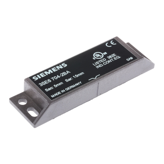
Zur Betätigung der Schaltelemente 3SE6604-2BA kann nur der
codierte 3SE6704-2BA verwendet werden; handelsübliche Mag-
nete sind nicht wirksam. Es ist immer an der angeschlossenen
Überwachungseinheit die korrekte Funktion zu überprüfen.
Es wird die Justage mittels des angegebenen Diagramms
empfohlen. Wenn sich die Mittelmarkierung des Magneten inner-
halb der dargestellten Grundeinstellungszone befindet, erfolgt an
der angeschlossenen Überwachungseinheit eine Freigabe. Die
angegebenen Schaltabstände beziehen sich auf gegenüber mon-
tierte Schalter und Magnete. Andere Anordnungen sind zwar
prinzipiell möglich, können aber zu anderen Abständen führen.
Technische Daten
Vorschriften:
EN 60947-5-3; in Verbindung mit Über-
wachungseinheiten z.B. 3TK284.- (Elek-
tronik) oder AS-Interface Safety at Work
Grenzabstände:*
s
s
Spannung:
max. 120 VAC/DC
Strom:
max. 250 mA
Leistung:
max. 3 VA / W
Umgebungstemperatur:
–25° . . . +70° C
Schwingungsfestigkeit:
10 . . . 55 Hz, Amplitude 1 mm
Schockfestigkeit:
30 g / 11 ms
Schutzart:
IP 67 (IEC/EN 60529/DIN VDE 0470-1)
Anschluss:
Leitung LiYY 4 x 0,25 mm
Leitungslänge:
max. 1000 m (bei Anschluss an Über-
wachungseinheit und Leitung
LiYY 4 x 0,75 mm
Adjustment
For operation of switch 3SE6604-2BA, only the coded magnet
3SE6704-2BA can be used; standard magnets are not effective.
Please always ccheck proper operation with the connected control
module. We recommend an adjustment procedure for all switches
using the specified diagramm. When the centre marking of the
magnet is within the active zone, the connected control unit will
provide an output signal. The specified switching distances refer to
opposedly mounted switch and magnets. Different arrangements
are possible, may lead to different switching distances, however.
Technical data
Standards:
EN 60947-5-3 in connection with
control unit e.g.. 3TK284.- Electronic)
or AS-Interface Safety at Work
Switching distances:*
s
s
Voltage:
max. 120 VAC/DC
Current:
max. 250 mA
Power rating:
max. 3 VA / W
Ambient temperature:
–25° . . . +70° C
Vibration resistance:
10 . . . 55 Hz, amplitude 1 mm
Shock resistance:
30 g / 11 ms
Enclosure sealing:
IP 67 (IEC/EN 60529/DIN VDE 0470-1)
Connection:
Cable LiYY 4 x 0,25 mm
Cable length:
max. 1000 m (in connection with
control unit and wire
LiYY 4 x 0,75 mm
3SE6604-2BA
3SE6704-2BA
Deutsch
= 5 mm
ao
= 15 mm
ar
2
2
)
English
= 5 mm
ao
= 15 mm
ar
2
2
(AWG 23)
Werbung

Inhaltszusammenfassung für Siemens 3SE6604-2BA
- Seite 1 The standard EN 60947-5-3 is only met by a complete system Adjustment magnetic interlock switch, coded magnet and control unit, e.g. For operation of switch 3SE6604-2BA, only the coded magnet 3TK284. (Electronic) or AS-Interface Safety at Work. 3SE6704-2BA can be used; standard magnets are not effective.
- Seite 2 Siemens AG, it’s subsidiaries Gesamtfunktion sicherzustellen. Die Siemens AG, ihre Niederlas- and affiliates (collectively ”Siemens”) is not in a position to evaluate sungen und Beteiligungsgesellschaften (im Folgenden ”Siemens”) all of the characteristics of a given machine or product.


