iKarus Craftair Montageanleitung

Verwandte Anleitungen für iKarus Craftair


Inhaltszusammenfassung für iKarus Craftair
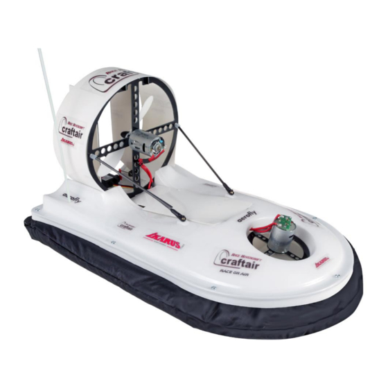
- Seite 1 4021001 Deutsch: Montageanleitung 1/10 Hovercraft „Craftair“ English: Assembly Instructions 1/10 scale Hovercraft “Craftair” 4029001-1108...
- Seite 2 Lieferumfang Ober- und Unterschale Schürzen ABS Platten GFK Frästeile CFK Rundmaterial Balsaklötze Antennenrohr Luftschrauben Haken- und Ösenband Kleinteile und Schrauben Zum Aufbau benötigen Sie außerdem: - Inbusschlüssel 1,5 mm - Skalpell - Spitzzange - Schere - Doppelseitiges Klebeband - Sekundenkleber, 2-Komponenten Kleber - Karosseriebohrer, Spiralbohrer Ø3 u.
-
Seite 3: Ober- Und Unterschale
Ober- und Unterschale Beschneiden Sie die Oberschale mit einer Schere entlang der Markierung, etwa 10 mm unterhalb des umlaufenden Randes. Im vorderen Bereich muss für den Hubmotorspant ein runder Ausschnitt entlang des Absatzes ausgeschnitten werden. Vor den nächsten Schritten empfehlen wir, die Scha- le von der Innenseite her mit geeigneter Sprühfarbe (z.B. - Seite 4 Aufbau Kleben Sie die Balsaklötze wie auf dem Bohrung Ø 3 mm für Antennenrohr Foto gezeigt, von innen fest und bohren Sie die 4 mm Bohrungen des langen Bal- Position frei saklotzes durch die Oberschale durch. Durch den kleinen Balsaklotz bohren Sie ein 3 mm Loch.
- Seite 5 Parallel...
- Seite 6 Die Elektronik (nicht im Bausatz enthalten) Schrauben Sie den Hauptmotor und den Hubmotor fest und verlegen Sie die Kabel (siehe Fotos auf den nächsten Seiten). Löten Sie je nach Version den oder die Regler an (siehe Schema unten). Das empfohlene Zubehör und Ersatzteile finden Sie am Ende dieser Anleitung. Batt 1 Regler System # 4023035...
- Seite 7 Die Elektronik (nicht im Bausatz enthalten)/ Der Duct Hängen Sie den Steuerdraht am großen Ruderhorn und am Servohebel ein. Positionieren Sie das Servo zwischen den Markierungen auf der Oberschale. Richten Sie das Servo so aus, dass bei Ser- vomittenstellung das Ruder genau in Längsrichtung steht. Kleben Sie das Servo in dieser Position fest.
- Seite 8 Abb. 3 Empfänger Akku Regler Blechschraube...
-
Seite 9: Tipps Zum Fahren
Hub-Antriebs) abbremsen, erhöht sich der Verschleiß. Gewährleistungsbestimmungen Für dieses IKARUS Produkt übernehmen wir eine Gewährleistung von 24 Monaten. Als Beleg für den Beginn und den Ablauf dieser Gewährleistung dient die Kaufquittung. Eventuelle Reparaturen verlängern den Ge- währleistungszeitraum nicht. Wenn im Garantiezeitraum Funktionsmängel, Fabrikations- oder Materialfehler auftreten, werden diese von uns behoben. -
Seite 10: Zubehör Und Ersatzteile
Zubehör und Ersatzteile Artikel-Nr. Bezeichnung 4026001 Brushed Set F2 Einreglersystem, beinhaltet Schubmotor 380 mit Propeller, Liftmotor 280 mit Propeller und Regler 30 A 4026003 Brushless Set, beinhaltet BL Schubmotor C26, Aluminiumadapter, Mutter und BL Regler 18 A. 68250 Luftschraube für Hub Brushed Set F2 4023005 Schürzen, 3 Stück...