RWA TRZ Plus DG Bedienungsanleitung

Verwandte Anleitungen für RWA TRZ Plus DG

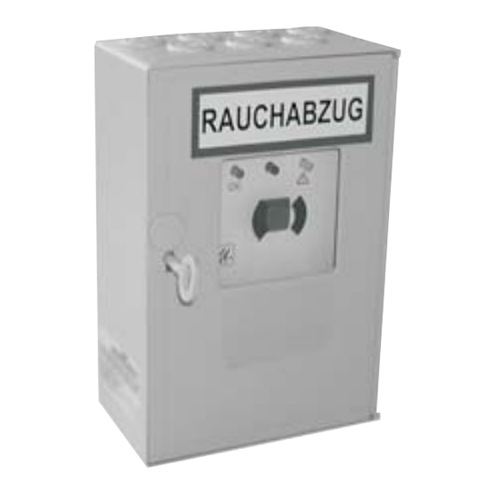
Inhaltszusammenfassung für RWA TRZ Plus DG
- Seite 1 RWA Treppenraumzentrale TRZ Plus DG Technische Information und Bedienungsanleitung SHE control panel TRZ Plus DG Technical information and operating instruction Centrala oddymiania klatek schodowych TRZ Plus DG Informacje techniczne i instrukcja obsługi...
-
Seite 2: Inhaltsverzeichnis
RWA Treppenraumzentrale TRZ Plus DG Inhalt Seite Funktion Besonderheiten Sicherheitshinweise Anschlussmöglichkeiten Montage Kabelplan Kabellängentabelle Integriertes TRZ Plus DG Modul Integrierte RWA-Bedienstelle Anschluss Netz Anschluss RWA-Bedienstelle Anschluss automatischer Melder Anschluss Brandmeldeanlage Anschluss Hupe / Signalleuchte Anschluss potenzialfreie Kontakte Anschlussübersicht DIP-Schalter Funktionen... -
Seite 3: Funktion
• mit integrierter RWA-Bedienstelle • Stromversorgung 24 V, Notstromakkus und Ladeteil, Parallelbetrieb, 72 Std. Funktionserhalt bei Netzausfall TRZ Plus DG • Leitungsüberwachung der Melderkreise (automatische Melder und RWA- Bedienstellen) • Leitungsüberwachung der angeschlossenen Druckgasgeneratoren • optische Störmeldung • separat abgesicherter Netzeingang 230 V AC / 50 Hz •... -
Seite 4: Sicherheitshinweise
Achtung: Nichtbeachtung führt zur Zerstörung Wartung: Wird das Produkt in Sicherheitssystemen, wie Gefährdung für Material durch falsche z. B. Rauch- und Wärmeabzugsanlagen (kurz RWA), Handhabung. eingesetzt, muss es gemäß Herstellerangabe oder z. B. nach DIN 18232-2 Rauch- und Wärmefreihaltung min- Wichtige Informationen destens einmal jährlich geprüft, gewartet und ggf. - Seite 5 RWA Treppenraumzentrale TRZ Plus DG Sicherheitshinweise Entsorgung: Verpackungen sind sachgerecht zu Leitungen für Kleinspannungen (z. B. 24 V DC) sind entsorgen. Die elektrischen Geräte sind an Sam- getrennt von Niederspannungsleitungen (z. B. 230 V AC) melstellen für die Rücknahme von Elektro- und Elektro- zu verlegen.
-
Seite 6: Anschlussmöglichkeiten
• 10 automatische Melder in 2-Leiter-Technik, optische Rauchmelder und/oder Wärmedifferential-Melder und/oder Wärmemaximal-Melder (Linienabschluss mit aktivem Endmodul) • zur potentialfreien Meldung Alarm (RWA-ausgelöst) und/oder Sammelstörung (max. 24 V / max. 0,5 A) • 24 V DC Sirene oder Blitzleuchte, max. 100 mA... -
Seite 7: Kabelplan
RWA Treppenraumzentrale TRZ Plus DG Kabelplan Druckgasgenerator 24 V DC max. 8 Stück automatische Melder (mit Überwachungswiderstand im letzten Meldersockel Kabeltyp siehe Kabellängentabelle! VDE Bestimmungen einhalten! Sirene V AC / DC 100 mA IY (ST) Y 2 x 2 x 0,8 mm, max. 100 m (siehe Hinweis) IY (ST) Y 2 x 2 x 0,8 mm, max. -
Seite 8: Integriertes Trz Plus Dg Modul
TRZ Plus DG Modul Schiebeschalter für “scharf” (ON) und “gesichert” (OFF) Das TRZ Plus DG Modul gehört zum Lieferumfang der TRZ Plus DG. Folgende Komponenten sind anschließbar: 8 x Druckgasgeneratoren 1 x potenzialfreie Weiterleitung Alarm (RWA-Auslösung) oder 1 x potenzialfreie Weiterleitung Sammelstörung, Kontaktbelastung max. 24 V / max. 0,5 A Funktion: Schiebeschalter für “scharf”... -
Seite 9: Anschluss Netz
RWA Treppenraumzentrale TRZ Plus DG Anschluss Netz Alle Arbeiten ohne Netz (230 V AC) und ohne angeschlossene Akkus/Batterien. Anschlussleitungen von oben in das Gehäuse der Steuerzentrale führen. Anschlussleitungen nach Klemmplan anklemmen, hierbei auf richtigen Anschluss achten. Falsches Anklemmen sowie Nummern- oder Farbendreher können zu Fehlfunktionen der Steuerzentrale oder der externen Elemente führen. -
Seite 10: Anschluss Rwa-Bedienstelle
RWA Treppenraumzentrale TRZ Plus DG Anschluss RWA-Bedienstelle Alle Arbeiten ohne Netz (230 V AC) und ohne angeschlossene Akkus/Batterien. Anschlussleitungen von oben in das Gehäuse der Steuerzentrale führen. Anschlussleitungen nach Klemmplan anklemmen, hierbei auf richtigen Anschluss achten. Falsches Anklemmen sowie Nummern- oder Farbendreher können zu Fehlfunktionen der Steuerzentrale oder der externen Elemente führen. -
Seite 11: Anschluss Automatischer Melder
RWA Treppenraumzentrale TRZ Plus DG Anschluss automatischer Melder Alle Arbeiten ohne Netz (230 V AC) und ohne angeschlossene Akkus/Batterien. Anschlussleitungen von oben in das Gehäuse der Steuerzentrale führen. Anschlussleitungen nach Klemmplan anklemmen, hierbei auf richtigen Anschluss achten. Falsches Anklemmen sowie Nummern- oder Farbendreher können zu Fehlfunktionen der Steuerzentrale oder der externen Elemente führen. -
Seite 12: Anschluss Brandmeldeanlage
RWA Treppenraumzentrale TRZ Plus DG Anschluss Brandmeldeanlage Alle Arbeiten ohne Netz (230 V AC) und ohne angeschlossene Akkus/Batterien. Anschlussleitungen von oben in das Gehäuse der Steuerzentrale führen. Anschlussleitungen nach Klemmplan anklemmen, hierbei auf richtigen Anschluss achten. Falsches Anklemmen sowie Nummern- oder Farbendreher können zu Fehlfunktionen der Steuerzentrale oder der externen Elemente führen. -
Seite 13: Anschluss Hupe / Signalleuchte
RWA Treppenraumzentrale TRZ Plus DG Anschluss Hupe / Signalleuchte Alle Arbeiten ohne Netz (230 V AC) und ohne angeschlossene Akkus/Batterien. Anschlussleitungen von oben in das Gehäuse der Steuerzentrale führen. Anschlussleitungen nach Klemmplan anklemmen, hierbei auf richtigen Anschluss achten. Falsches Anklemmen sowie Nummern- oder Farbendreher können zu Fehlfunktionen der Steuerzentrale oder der externen Elemente führen. -
Seite 14: Anschluss Potenzialfreie Kontakte
RWA Treppenraumzentrale TRZ Plus DG Anschluss potenzialfreie Kontakte Alle Arbeiten ohne Netz (230 V AC) und ohne angeschlossene Akkus/Batterien. Anschlussleitungen von oben in das Gehäuse der Steuerzentrale führen. Anschlussleitungen nach Klemmplan anklemmen, hierbei auf richtigen Anschluss achten. Falsches Anklemmen sowie Nummern- oder Farbendreher können zu Fehlfunktionen der Steuerzentrale oder der externen Elemente führen. -
Seite 15: Anschlussübersicht
RWA Treppenraumzentrale TRZ Plus DG Anschlussübersicht Alle Arbeiten ohne Netz (230 V AC) und ohne angeschlossene Akkus / Batterien. Anschlussleitungen von oben in das Gehäuse der Steuerzentrale führen. Anschlussleitungen nach Klemmplan anklemmen, hierbei auf richtigen Anschluss achten. Falsches Anklemmen sowie Nummern- oder Farbendreher können zu Fehlfunktionen der Steuerzentrale oder der externen Elemente führen. -
Seite 16: Dip-Schalter Funktionen
RWA-Auslösung, BMA-Kontakt geöffnet = RWA-Reset sowie Schließen der Klappen/Fenster. Eine Kombination mit automatischen Meldern ist möglich, jedoch erfolgt ein Reset der Melder ausschließlich über die RWA-Resettaste der TRZ-Plus oder bei Konfi guration DIP-Schalter 8 = ON zusätzlich über die ZU-Taste einer angeschlossenen RWA-Bedienstelle. -
Seite 17: Service Port
Über den Service Port (PC Schnittstelle) können mit der entsprechenden Service-Port-Konfi gurationssoftware* sowie mit einem Verbindungskabel* bestimmte Funktionen mit weiteren Parametern versehen werden. Die Funktionen sind abhängig von der PC Softwareversion und der Firmware der RWA-Zentrale. Der Wartungstimer kann ausschließlich über die Software zurückgesetzt werden. -
Seite 18: Abschließende Arbeiten
Taste RWA-Reset in der Steuerzentrale (auf der Platine) drücken. Die rote Anzeige im automatischen Melder erlischt. Die gelbe LED Anzeige - Störung - blinkt (Blinkcode 5). Auf dem TRZ Plus DG Modul blinkt jetzt die gelbe LED “OFF“. Anschließend wird der Schiebeschalter in der Zentrale in Stellung “scharf” geschaltet. -
Seite 19: Störungshilfe
Wartungsanzeige (gleichmäßiges Blinken) Wartung Grüne LED - Betrieb OK - blinkt gleichmäßig: Reset bzw. Setzen des Wartungstimers über die Konfi gurations-Software zur TRZ Plus DG. Weitere Informationen siehe technische Informationen zur PC Software Service Port zur TRZ Plus DG. 04/24999499... -
Seite 20: Wartung
Die Bedienungsanleitungen der angeschlossenen Komponenten sind unbedingt zu beachten! Außer Betrieb Um die RWA-Anlage außer Betrieb zu nehmen, muss die Zentrale vom Netz getrennt und die Batteriesicherung entfernt werden. Während der Außerbetriebnahme stoppt der aktivierte Wartungstimer und speichert die letzten Daten. -
Seite 21: Technische Daten
RWA Treppenraumzentrale TRZ Plus DG Technische Daten Die Energieversorgungen und elektrischen Steuereinrichtungen sind ausschließlich mit den vom Hersteller zugelassenen Komponenten zu betreiben. Elektrische Eigenschaften Primäre Energieversorgung Netzversorgungsspannung: 230 V AC / 50 Hz, (±10 %), separat abgesichert Systemspannung: 27 V DC (Nenn) (-25 % / +10 %) Leistungsaufnahme: max. - Seite 22 RWA Treppenraumzentrale TRZ Plus DG Technische Daten Potenzialfreier Kontakt RWA-Auslösung und/oder Sammelstörung: Wechslerkontakt max. 30 V DC / 0,5 A Mechanische Eigenschaften Maße: siehe Seite 20 Gewicht: ca. 8 kg mit Akku, ca. 3 kg ohne Akku Anschluss und Betrieb...
- Seite 23 RWA Treppenraumzentrale TRZ Plus DG Technische Daten Hinweispfl icht nach § 12 der Batterieverordnung (BattV) Im Zusammenhang mit dem Vertrieb von Batterien und Akkus sind wir als Händler gemäß Batterieverordnung verpfl ichtet, Sie als Verbraucher auf folgendes hinzuweisen: - Jeder Endverbraucher ist gesetzlich verpfl ichtet, Batterien und Akkus zurückzugeben! - Sie können diese nach Gebrauch in unseren Werken oder in einer kommunalen Sammelstelle zurück geben.