Harvia C80/1 Bedienungsanleitung
Vorschau ausblenden
Andere Handbücher für C80/1:
- Bedienungsanleitung (52 Seiten) ,
- Bedienungsanleitung (11 Seiten) ,
- Bedienungsanleitung (12 Seiten)

Verwandte Anleitungen für Harvia C80/1


Inhaltszusammenfassung für Harvia C80/1
- Seite 1 This product has changed in 03/2010. Click here to download instructions for installation and use for the earlier version. Das Produkt hat sich ab 03/2010 geändert. Hier klicken um auf die Seite dieser Gebrauchs- und Montageanleitung zu gelangen. C80/1, C90, C150 Control units Steuergeräte...
- Seite 2 ContentS InhALt 1. ContRoL UnItS C80/1, C90 AnD C150 .....3 1. SteUeRGeRÄte C80/1, C90 UnD C150 ......3 1.1. General .................3 1.1. Allgemeines ..............3 1.2. Technical Data ...............3 1.2. Technische Daten ............3 2. InStRUCtIonS FoR USe ...........3 2. BeDIenUnGSAnLeItUnG ...........3 3. InStRUCtIonS FoR InStALLAtIon ......5 3.
-
Seite 3: Control Units
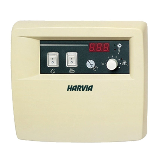
C80/1, C90 AnD C150 C80/1, C90 UnD C150 1.1. General 1.1. Allgemeines Control unit C80/1 is intended for the control of Das C80/1-Steuergerät ist für die Steuerung ein- 1-phase sauna heaters (2–6 kW) in family saunas phasiger elektrischer Öfen (2–6 kW) in Familien-... - Seite 4 Figure 1. Abbildung 1. 1. Main switch 1. hauptschalter Start the heater by pressing the main switch to posi- Die Inbetriebnahme des Saunaofens erfolgt durch tion 1. The heater begins to warm up immediately. Drücken des Hauptschalters in Position 1. Der Ofen The heater turns off when the on-time runs out or beginnt sofort sich zu erwärmen.
-
Seite 5: Instructions For Installation
3. InStRUCtIonS FoR InStALLAtIon 3. InStALLAtIonSAnLeItUnG the electrical connections of the control unit may only Die elektrischen Anschlüsse des Steuergeräts dürfen be made by an authorised, professional electrician nur von einem autorisierten, geschulten elektriker and in accordance with the current regulations. unter Beachtung der aktuell gültigen Vorschriften When the installation of the control unit is complete, vorgenommen werden. - Seite 6 The cable enclosed with the thermostat is made Luftzufuhr geändert werden. of silicon and can withstand temperatures of up Das Kabel, das zusammen mit dem Thermostat to +170 °C. The cable can be extended with geliefert werden, ist aus Silikon und ist bis 170 °C lower temperature cable having a corresponding wärmebeständig.
- Seite 7 3.4. Changing the Settings 3.4. Ändern der einstellungen Open the settings menu: Öffnen Sie das Einstellungsmenü: 1. Switch the power off from the main switch 1. Schalten Sie den Strom am Hauptschalter ab (position 0) (Position 0). 2. Press and hold the pre-setting time button and 2.
- Seite 8 Figure 6. Reset button for overheat protector Abbildung 6. Rücksetzknopf des Überhitzungsschutzes Figure 7. Electronic cards Abbildung 7. Elektronikplatten...
- Seite 9 Description/Beschreibung Remedy/Abhilfe Temperature sensor's measuring Check the red and yellow wires to the temperature sensor and their circuit broken. connections for faulties. Messkreis des Temperaturfühlers Prüfen Sie die roten und gelben Kabel zum Temperaturfühler und deren unterbrochen. Verbindungen auf Fehler. Temperature sensor's measuring Check the red and yellow wires to the temperature sensor and their circuit short-circuited.
- Seite 10 Figure 9. Abbildung 9. Output Cables/fuses Leistung Kabel/Sicherungen Fuses B (H07RN-F) C (T170 °C) D (SSJ) Sicherungen mm² min. mm² mm² mm² mm² 4 x 1,5 2 x 10 4 x 1,5 4 x 0,25 3 x 1,5 3 x 1,5 <4,5–6,9 5 x 1,5 3 x 10...