hager HR510 Bedienungsanleitung
Quicklinks
6 0
5 1 0
4 5
H R
1 3
0, 5
3 0
0, 4
10
1 3
0, 3
1 5
5
0, 1
t( s )
3
0
5
1
(A )
03
I n
e t
R e s
t
T e s
HR510, HR520
HR510
N Ph
9
7
8
9
10
11
HR510
ON
4
1 3 10
0,5 1 3
0,5
0,4
0,3
0,3
5
0,1
0,1
0,03
0
I n(A)
t(s)
2
Test
Reset
1
2
3
4
5
7
10
7
8 9 10
11 12
6 A
6 A
1
2 3 4
5
6
HR520
N
10
Ph
7
8
9
10
11
HR520
75
ON
4
60
1 3 10
0,5 1 3
0,5
0,4
45
0,3
0,3
5
0,1
0,1
30
0,03
0
I n(A)
t(s)
15
2
5
Test
Reset
1
2
3
4
5
7
8
1
¢
Relais différentiels
§
Earth leakage relay
£
FI-Relais
ß
Relés diferenciales
®
Relés diferenciais
FR
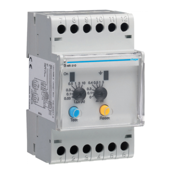
Présentation du produit
Œ
poussoir "reset" : en cas de déclenchement,
la sortie reste en basculement et le retour à la normale
est obtenu par :
- une impulsion sur le BP d'acquittement "reset"
- une coupure de l'alimentation.
poussoir "test" : l'impulsion sur le BP "test"
12
permet de vérifier, par une simulation,
le bon fonctionnement du relais en cas de défaut.
Ž
voyant de défaut : allumé lors d'un défaut
de l'installation surveillée. Clignotant lors d'une rupture
de la liaison relais/tore.
3
voyant de présence tension :
bon fonctionnement du produit.
6
calibres IΔn
‘
temporisation Δt
1
- réglages plombables : toute modification de réglage
peut être proscrite par un capot plombable.
’
sortie standard (1 OF) :
6
déclenchement à 85 % de IΔn à ±15 %.
Passe de 0 à 1 lors d'un
- défaut de la liaison tore/relais,
- courant de défaut dans l'installation surveillée.
ou sortie à sécurité positive (1 OF) :
basculement à 1 lors de la mise sous tension,
passe de 1 à 0 lors :
- d'un défaut de liaison tore-relais,
- courant de défaut dans l'installation surveillée,
N L1 L2 L3
- défaut d'alimentation ou interne du relais.
“
sortie à sécurité positive (1 OF) HR520 :
basculement à 1 lors de la mise sous tension,
passe de 1 à 0 lors :
- d'un défaut de liaison tore-relais,
- courant de défaut dans l'installation surveillée
- défaut d'alimentation ou interne du relais.
”
entrée de sélection du type de sortie :
- pas de connection entres bornes 10 et 11 :
’
contact
- connection entre bornes 10 et 11 :
’
contact
•
sortie préalarme (1O HR520 ; 1O HR510) :
le contact s'ouvre à 50 % de IΔn (±15 %)
1 1
barregraph (HR520) : indique en permanence
la valeur du courant de fuite, 5 à 15 %, 15 à 30 %,
30 à 45 %, 45 à 60 % et 60 à 75 % de IΔn.
Spécifications techniques
Relais :
- Relais :
- Tension d'alimentation :
- Tension du réseau contrôlé :
- Puissance absorbée :
- Calibres IΔn :
- Temporisation Δt :
- Temps de déclenchement :
- Sortie standard (1 OF) :
- Sortie sécurité positive (1 OF) : 6 A / 250 V AC1
12
- Sortie préalarme (1 F) :
- Raccordt. des câbles :
11
- Couple de serrage :
- Longueur maxi liaison test, reset : 20 m (1,5
3
- Longueur maxi liaison tore/relais : 20 m (1,5
- T° de stockage :
6
- T° de fonctionnement :
Tores :
1
- Surcharge admissible :
- T° de stockage :
6
- T° de fonctionnement :
Normes :
IEC 60 755:2008, IEC 60947-2:2006 annexe M,
IEC 61 543, IEC 61008-1:2010,
IEC 61000-6-1:2005 & IEC 61000-6-3:2006
standard.
à sécurité positive.
type A ≤ 3 A - type AC > 3 A
50/60 Hz 230 V ±20 %
50/60 Hz 50 à 700 V
5 VA
0,03 / 0,1 / 0,3 / 0,5 / 1 / 3 / 10 A
0 / 0,1 / 0,3 / 0,4 / 0,5 / 1 / 3 s (±20 %)
IΔn = 50 ms
1,5 à 2,5 IΔn = 40 ms ;
> 2,5 IΔn = 20 ms
6 A / 250 V AC1
6 A / 250 V AC1
„
„
rigide 1,5
à 10
„
„
souple 1
à 6
1,7 Nm
„
)
„
)
-25 à +70 °C
-10 à +55 °C
5 kA / 1,5 s - 14 kA / 1 s - 100 kA / 0,05 s
-25 à +70 °C
-10 à +55 °C
Notice d'instructions
User instructions
Bedienungsanleitung
Manual de instrucciones
Instruções de instalação
GB
Product presentation
Œ
"reset" push button: in case of tripping,
the output remains commutated and the return
to "normal" position is made by:
- pushing the "reset" push button
- a power cut.
"rest" push button: it allows to verify,
by a simulation, the good functioning of the relay
in case of fault.
Ž
Fault indicator: it is switched on when fault
of the supervised installation.
Intermittent when there is a breaking of the
relay/torroïd connection.
Supply indicator: good functioning of the product.
Δ
I
n ratings
‘
Δ
Temporization
t
- sealing adjustments: all modifications of
adjustment can be done by a sealing cover.
’
Standard output (1 OF) : tripping at 85%
of IΔn ±15 %.
Goes from 0 to 1 when:
- fault when torroïd/relay connection
- fault current when supervised installation.
or positive safety output:
Goes to 1 when supply, goes from 1 to 0 when :
- fault of torroïd/relay connection,
- fault current when supervised installation,
- supply fault or internal relay fault.
“
Positive safety output (1 OF) HR520 :
Goes to 1 when supply, goes from 1 to 0 when :
- fault of torroïd/relay connection,
- fault current when supervised installation,
- supply fault or internal relay fault.
”
entrée Input for changing the output contact :
- no connexion between terminals 10 and 11 :
’
contact
standard output.
- connexion between terminals 10 and 11 :
’
contact
positive safety output.
•
Pre-alarm output (1O HR520 ; 1O HR510) :
the contact opens itself at 50% of IΔn (±15%)
1 1
Barregraph (HR520 : indicates continuously
the value of the leakage current,
5 to 15 %, 15 to 30 %, 30 to 45 %, 45 to 60 %
and 60 to 75 % of IΔn.
Technical specifications
Relais :
- Relay :
type A ≤ 3 A - type AC > 3 A
- Supply voltage:
50/60 Hz 230 V ±20 %
- Supervised power voltage: 50/60 Hz 50 to 700 V
- Consommation:
5 VA
- Ratings IΔn:
0,03 / 0,1 / 0,3 / 0,5 / 1 / 3 / 10 A
- Temporization Δt: 0 / 0,1 / 0,3 / 0,4 / 0,5 / 1 / 3 s (±20 %)
- Tripping time:
IΔn = 50 ms
1,5 to 2,5 IΔn = 40 ms;
> 2,5 IΔn = 20 ms
- Standard output (1OF):
6 A / 250 V AC1
- Positive safety output:
(1 OF) : 6 A / 250 V AC1
- Pre-alarm output (1 F):
6 A / 250 V AC1
- Cables connectio :
rigid 1,5
flexible 1
- Torque setting:
1,7 Nm
- Maxi length of test/reset connection: 20 m (1,5
- Maxi length of torroïd/relay connection: 20 m (1,5
- Storage temperature:
-25 to +70 °C
- Functioning temperature:
-10 to +55 °C
Torroïds :
- Allowed overload:
5 kA / 1,5 s - 14 kA / 1 s - 100 kA / 0,05 s
- Storage temperature:
-25 to +70 °C
- Functioning temperature:
-10 to +55 °C
:
Standards
IEC 60 755:2008, IEC 60947-2:2006 annex M,
IEC 61 543, IEC 61008-1:2010,
IEC 61000-6-1:2005 & IEC 61000-6-3:2006
„
„
to 10
„
„
to 6
„
)
„
)

Verwandte Anleitungen für hager HR510


Inhaltszusammenfassung für hager HR510
- Seite 1 ’ ’ contact positive safety output. contact standard. • Pre-alarm output (1O HR520 ; 1O HR510) : - connection entre bornes 10 et 11 : ’ the contact opens itself at 50% of IΔn (±15%) contact à sécurité positive. •...
- Seite 2 - kein Anschluss zwischen 10 und 11 : ’ Standard Alarmkontakt • Pre-alarm output (1 F, HR520 ; 1 OF, HR510) : der Kontakt öffnet bei 50% IΔn (±15%) LED Anzeige (HR520) : zeigt ständig den Fehlerstrom, 8 9 10...
- Seite 3 ’ contacto estándar. contacto saída de segurança positiva. • Saída pré-alarme (1O HR520; 1O HR510): 8 9 10 11 12 - conexión entre bornes 10 y 11: ’ O contacto troca a 50 % de IΔn (± 15 %) contacto a seguridad positiva.
- Seite 4 6H 5054.e...