Inhaltsverzeichnis
Werbung
Verfügbare Sprachen
Verfügbare Sprachen
Werbung
Kapitel
Inhaltsverzeichnis

Verwandte Anleitungen für Siemens CP 5512

Inhaltszusammenfassung für Siemens CP 5512
- Seite 1 Inhaltsverzeichnis Leistung und Funktionen Netzwerkkarte installieren Entfernen eines SIMATIC NET CP 5512 aus dem PC CP 5512 Technische Daten CE-Kennzeichnung Installationsanleitung/ Produktinformation Ausgabe 08/2005 A5E00175148 - 02...
- Seite 2 Copyright E Siemens AG 1996/2002 All rights reserved Haftungsausschluß Wir haben den Inhalt der Druckschrift auf Weitergabe sowie Vervielfältigung Übereinstimmung mit der beschriebenen dieser Unterlage, Verwertung und Hard-und Software geprüft. Dennoch kön- Mitteilung ihres Inhalts ist nicht ge- nen Abweichungen nicht ausgeschlossen stattet, soweit nicht ausdrücklich...
- Seite 3 Tod, schwere Körperverletzung oder er- heblicher Sachschaden eintreten werden, wenn die entsprechenden Vorsichtsmaßnahmen nicht getroffen werden. Warnung bedeutet, daß Tod, schwere Körperverletzung oder er- heblicher Sachschaden eintreten können, wenn die entsprechenden Vorsichtsmaßnahmen nicht getroffen werden. CP 5512 Installationsanleitung/Produktinformation A5E00175148-02...
- Seite 4 Folgen haben kann. Hinweis ist eine wichtige Information über das Produkt, die Handhabung des Produktes oder den jeweiligen Teil der Dokumentation, auf den beson- ders aufmerksam gemacht werden soll und deren Beachtung wegen eines möglichen Nutzens empfohlen wird. CP 5512 Installationsanleitung/Produktinformation A5E00175148-02...
-
Seite 5: Sicherheitstechnische Hinweise Zu Ihrem Produkt
Marken SIMATICR, SIMATIC HMIR und SIMATIC NETR sind eingetragene Marken der SIEMENS AG. Die übrigen Bezeichnungen in dieser Schrift können Mar- ken sein, deren Benutzung durch Dritte für deren Zwecke die Rechte der Inhaber verletzen können. Sicherheitstechnische Hinweise zu Ihrem Produkt:... -
Seite 6: Bestimmungsgemäßer Gebrauch Von Hardware -Produkten
Warnung Das Gerät darf nur für die im Katalog und in der techni- schen Beschreibung vorgesehenen Einsatzfälle und nur in Verbindung mit von Siemens empfohlenen bzw. zuge- lassenen Fremdgeräten und -komponenten verwendet werden. Der einwandfreie und sichere Betrieb des Produktes setzt sachgemäßen Transport, sachgemäße Lagerung,... -
Seite 7: Weitere Unterstützung
Beachten Sie folgendes: Warnung Die Software darf nur für die im Katalog und in der tech- nischen Beschreibung vorgesehenen Einsatzfälle und nur in Verbindung mit von Siemens empfohlenen bzw. zugelassenen Software-Produkten, Fremdgeräten und -komponenten verwendet werden. Bevor Sie mitgelieferte Beispielprogramme oder selbst erstellte Programme anwenden, stellen Sie sicher, dass in laufenden Anlagen keine Schäden an Personen oder... - Seite 8 ....Netzwerkkarte installieren ....Entfernen eines CP 5512 aus dem PC ..Technische Daten .
-
Seite 9: Leistung Und Funktionen
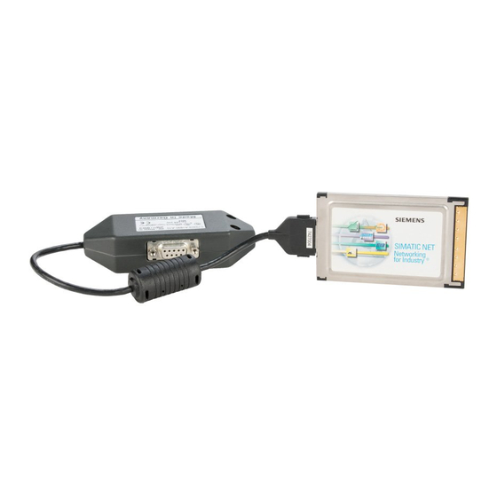
PC -Card Busadapter Produktinformation Hardwarevoraussetzungen Der CP 5512 kann in jedem PG, PC bzw. Note- book mit einem 32 -Bit-PC -Card (Cardbus) Typ II oder Typ III (PC Card Standard Specification, Re- lease 5 Feb. 1995) Steckplatz betrieben werden. Der CP 5512 benötigt einen Interrupt sowie einen Speicherbereich von min. -
Seite 10: Netzwerkanschlüsse
Schraubverriegelung kann das PROFIBUS -Ka- bel über ein Busterminal angeschlossen werden. Sicherheit Der CP 5512 stellt für die Versorgung der Ab- schlusswiderstände, die im aufgesteckten Buster- minal zugeschaltet werden können, eine Span- nung von 5 V zu Verfügung. Diese darf maximal mit 10 mA belastet werden. -
Seite 11: Netzwerkkarte Installieren
Detaillierte Installationsanleitungen zur Software finden Sie bei dem jeweiligen Softwareprodukt. 3. Vor dem Stecken des CP 5512 in den PC -Cardbus Adapter muss der Busadapter mit dem CP 5512 verbunden werden. 4. Stellen Sie sicher, dass auf den CP 5512 keine Zugkräfte durch den angeschlossenen Busadapter einwirken. -
Seite 12: Anschluss An Den Profibus
3. Stellen Sie sicher, dass auf den Busadapter keine Zugkräfte durch die angeschlossene PROFIBUS -Leitung einwirken. Vorsicht Die im Busterminal zuschaltbaren Abschlusswiderstände dürfen nur an der Station am Kabelanfang und der Station am Kabel - ende zugeschaltet werden. CP 5512 Installationsanleitung/Produktinformation A5E00175148-02... -
Seite 13: Steckerbelegung Der Profibus-Schnittstelle
Versorgung der Busterminierung und darf maximal mit 10 mA belastet werden. Weitere Informationen zum Aufbau oder zur Projektierung von PROFIBUS-Netzen entnehmen Sie den folgenden Druckschrif- ten: Handbuch für PROFIBUS Netze 6GK1970 -5CA10 -0AA0 CP 5512 Installationsanleitung/Produktinformation A5E00175148-02... -
Seite 14: Entfernen Eines Cp 5512 Aus Dem Pc
Entfernen eines CP 5512 aus dem PC Entfernen eines CP 5512 aus dem PC Vorgehensweise Bevor ein CP 5512 endgültig aus dem PC ent- fernt werden soll, müssen folgende Schritte aus- geführt werden: 1. Der CP muss zuerst in den PG -Betrieb ver- setzt werden. - Seite 15 Entfernen eines CP 5512 aus dem PC Installation CP 5511 Wenn Sie nach dem Entfernen eines CP 5512 einen CP 5511 stecken, kann es in seltenen Fäl- len passieren, dass der Rechner unbedienbar wird. Abhilfe: Ziehen Sie in diesem Fall den CP 5511 noch ein- mal und stecken Sie ihn anschließend wieder.
-
Seite 16: Technische Daten
3,3 VDC (3.0 V bis 3,6 V) Stromaufnahme bei Nennspan- typ. 520 mA nung MTBF 135 Jahre Steckverbinder zum 9polige D-SUB-Buchsenleiste mit PROFIBUS Schraubverriegelung Übertragungsart RS 485 erdfrei innerhalb der SELV- Grenzen Störaussendung B nach EN 55011 FCC-Class CP 5512 Installationsanleitung/Produktinformation A5E00175148-02... - Seite 17 IEC 61000-4-6/ EN6100-4-6 Stromversorgungsleitung, Bus- leitung, Erdanschluss Entladung statischer Elektrizität ±6kV Kontaktentladung nach EN 61000-4-2 / IEC ±6kV Luftentladung 61000-4-2 (ESD) Schnelle Transienten nach EN ±2kV 61000-4-4 / IEC 61000-4-4 (Burst) µs -Impulse nach IEC ±2kV 61000-4-5 (Surge) CP 5512 Installationsanleitung/Produktinformation A5E00175148-02...
- Seite 18 5 - 8,5 Hz: Amplitude 3,5 mm 8,5 - 500 Hz: Beschleunigungsam- plitude 10 m/s (1 g) Schocken (geprüft nach IEC 68-2-27/EN 60068-27) in Betrieb Halbsinus 50 m/s (5 g), 30 ms bei Transport Halbsinus 250 m/s (25 g), 6 ms CP 5512 Installationsanleitung/Produktinformation A5E00175148-02...
- Seite 19 Technische Daten Mechanische Daten Maße (LxBxH) CP 5512 85,6 x 54 x 5 mm Busadapter ca. 106 x 47 x 25 mm Leitungslänge ohne Stecker ca. 20 Gewicht ca. 135 g Prüfzeichen CE, CUL, FCC CP 5512 Installationsanleitung/Produktinformation A5E00175148-02...
-
Seite 20: Produktbezeichnung
EU -Richtlinie 89/336/EWG ”Elektromagnetische Verträglichkeit”. Die EU -Konformitätserklärung wird gemäß der obengenannten EU -Richtlinie für die zuständigen Behörden zur Verfügung gehalten bei: Siemens Aktiengesellschaft Bereich Automatisierungs - und Antriebstechnik Industrielle Kommunikation (A&D PT2) Postfach 4848 D -90327 Nürnberg CP 5512 Installationsanleitung/Produktinformation A5E00175148-02... -
Seite 21: Einsatzbereich
EN 61000 -6 -2 : 1999 Aufbaurichtlinien beachten Das Produkt erfüllt die Anforderungen, wenn Sie bei Installation und Betrieb die Aufbaurichtlinien einhalten, die in folgenden Dokumentationen be- schrieben sind: 1. PROFIBUS Netzhandbuch 2. Einbauanweisung im Handbuch Ihres Endge- rätes CP 5512 Installationsanleitung/Produktinformation A5E00175148-02... -
Seite 22: Arbeiten Am Produkt
Das Produkt wurde in einem Gerät getestet, das ebenfalls die oben genannten Normen einhält. Beim Betrieb der Baugruppe in einem Gerät, das diese Normen nicht erfüllt, kann die Einhaltung der entsprechenden Werte nicht garantiert wer- den. CP 5512 Installationsanleitung/Produktinformation A5E00175148-02... -
Seite 23: Erklärung Über Die Erfüllung Der Fcc-Vorschriften
Maßnahmen zu beseitigen: Richten Sie die Empfangsantenne anders aus oder stellen Sie diese an einem anderen Ort auf. Vergrößern Sie den Abstand zwischen dem Gerät und dem Empfangsgerät. Schließen Sie das Gerät an eine Netzsteckdose an, die sich CP 5512 Installationsanleitung/Produktinformation A5E00175148-02... - Seite 24 Anschluss verursacht werden, obliegt dem Anwender. Zum Anschluss dieses Gerätes an sämtli- che optionalen Peripheriegeräte oder Host -Geräte sind ab- geschirmte E/A -Kabel erforderlich. Eine Nichtbeachtung dieser Anforderung kann einen Verstoß gegen die FCC -Vor- schriften darstellen. CP 5512 Installationsanleitung/Produktinformation A5E00175148-02...
-
Seite 25: Konformitätserklärung
001 (770) 871 -3867 Fax: 001 (770) 871 -3999 SIEMENS Energy & Automation, Inc. erklärt hiermit, dass das Produkt mit der oben angegebenen Handelsbezeichnung und Modellnummer unter Anwendung der exaktesten Messverfah- ren nach den relevanten FCC -Vorschriften geprüft wurde und dass alle nötigen Maßnahmen ergriffen wurden und werden,... - Seite 26 Telefon: +86 10 64 71 99 90 Fax: +49 (0) 180 5050-223 Fax: +1 (423) 262 2289 Fax: +86 10 64 74 74 74 Internet www.siemens.de/ automation/support - E-Mail: simatic.hotline@ E-Mail: adsupport.asia@ request sea.siemens.com siemens.com GMT: +1:00 GMT: -5:00 GMT: +8:00 CP 5512 Installationsanleitung/Produktinformation A5E00175148-02...
-
Seite 27: Service & Support Im Internet
Ansprechpartner-Datenbank. Informationen über Vor-Ort Service, Reparaturen, Ersatz- teile. Vieles mehr steht für Sie unter dem Bergriff ”Leistun- gen” bereit. Ihren Ansprechpartner für Automation & Drives vor Ort finden Sie über unsere Ansprechpartner -Datenbank unter http://www.automation.siemens.com/partner CP 5512 Installationsanleitung/Produktinformation A5E00175148-02... - Seite 28 CP 5512 Installationsanleitung/Produktinformation A5E00175148-02...
- Seite 29 Contents Performance and Functions Installing the Network Card Removing a CP 5512 SIMATIC NET from the PC CP 5512 Technical Specifications CE Mark Installation Instructions/ Product Information Dated 08/2005 A5E00175148-02...
- Seite 30 Copyright E Siemens AG 1996/2002 All rights reserved Disclaimer of Liability We have checked the contents of this ma- The reproduction, transmission or nual for agreement with the hardware and use of this document or its contents software described. Since deviations can-...
- Seite 31 Caution indicates that minor personal injury or property damage can result if proper precautions are not taken. CP 5512 Installation Instructions/Product Information A5E00175148-02...
- Seite 32 Note highlights important information on the product, using the product, or part of the documentation that is of particular importance and that will be of benefit to the user. CP 5512 Installation Instructions/Product Information A5E00175148-02...
-
Seite 33: Trademarks
Qualified persons are defi- ned as persons who are authorized to commission, to ground, and to tag circuits, equipment, and systems in accordance with established safety practices and stan- dards. CP 5512 Installation Instructions/Product Information A5E00175148-02... - Seite 34 EU Directive: Do not start up until you have established that the machine on which you intend to run this compo- nent complies with the directive 89/392/EEC. CP 5512 Installation Instructions/Product Information A5E00175148-02...
-
Seite 35: Further Support
Further Support If you have further questions about SIMATIC NET products, contact your local Siemens representa- tive. You will find the addresses: In our catalog IK PI on the Internet (http://www.ad.siemens.de) - Seite 36 ....Installing the Network Card ....Removing a CP 5512 from the PC ..Technical Specifications .
-
Seite 37: Performance And Functions
Performance and Functions The CP 5512 is a 32 -bit PC card (CardBus) with a bus adapter for PROFIBUS up to 12 Mbps. The additional interface signals for direct coupling to the PLC (programmable logic controller) are sup- ported up to 187.5 Kbauds. - Seite 38 9-pin sub D socket connector with screw locking mechanism via a bus terminal. Safety The CP 5512 supplies a voltage of 5 V for the terminating resistors that can be activated on the connected bus terminal. The maximum load must not exceed 10 mA.
-
Seite 39: Installing The Network Card
3. The CP 5512 must be connected to the busadapter before the CP 5512 is inserted in the PC Cardbus adapter. 4. Make sure that no tensile stress is exerted on the CP 5512 by the connected bus adapter. Caution When you remove the CP 5512, make sure that you use the ejector of the PC card port. - Seite 40 3. Make sure that no tensile stress is exerted on the bus adap- ter by the connected PROFIBUS cable. Caution The terminating resistors must only be activated on the station at the start and the end of the cable. CP 5512 Installation Instructions/Product Information A5E00175148-02...
- Seite 41 10 For more detailed information on the structure and configuration of PROFIBUS networks, refer to the following documentation: Manual for PROFIBUS Networks 6GK1970-5CA10-0BA0 CP 5512 Installation Instructions/Product Information A5E00175148-02...
-
Seite 42: Removing A Cp 5512 From The Pc
Removing a CP 5512 from the PC Procedure Before a CP 5512 is removed finally from the PC, the following steps must be taken: 1. The CP must first be set to PG operation. To do this, go to the Station Configuration Editor and deleted the CP 5512 there. - Seite 43 Removing a CP 5512 from the PC Installing the CP 5511 If you insert a CP 5511 after removing a CP 5512, in rare cases, the computer may not respond to input. Remedy: In this case, remove the CP 5511 again and insert it again.
-
Seite 44: Technical Specifications
MTBF 135 years Connector to 9-pin sub D female connector with PROFIBUS screw locking mechanism. Type of transmission RS 485 floating within the SELV li- mits Noise emission B to EN 55011 FCC class CP 5512 Installation Instructions/Product Information A5E00175148-02... - Seite 45 ±6 kV contact discharge complying with EN 61000-4-2 / ±6 kV air discharge IEC 61000-4-2 (ESD) Fast transients complying with ±2kV EN 61000-4-4 / IEC 61000-4-4 (burst) µs pulses complying with IEC ±2kV 61000-4-5 (surge) CP 5512 Installation Instructions/Product Information A5E00175148-02...
- Seite 46 5 - 8.5 Hz: Amplitude 3.5 mm 8.5 - 500 Hz: Acceleration 10 m/s (1 g) Shock (tested to IEC 68-2-27/EN 60068-27) Operation Half-sine 50 m/s (5 g), 30 ms Transport Half-sine 250 m/s (25 g), 6 ms CP 5512 Installation Instructions/Product Information A5E00175148-02...
- Seite 47 85.6 x 54 x 5 mm 5512 Bus adapter approx. 106 x 47 x 25 mm Cable length without connector ap- prox. 20 cm Weight approx. 135 g Marks of conformity CE, CUL, FCC CP 5512 Installation Instructions/Product Information A5E00175148-02...
-
Seite 48: Product Name
The EU conformity certificate is available for the relevant authorities according to the above EU directive and is kept at the following address: Siemens Aktiengesellschaft Bereich Automatisierungs- und Antriebstechnik Industrielle Kommunikation (A&D PT2) Postfach 4848 D-90327 Nürnberg CP 5512 Installation Instructions/Product Information A5E00175148-02... -
Seite 49: Area Of Application
The product meets the requirements providing you adhere to the guidelines for installation and operation described in the following documenta- tion: 1. PROFIBUS Network Manual; 2. Installation instructions in the manual of your target device. CP 5512 Installation Instructions/Product Information A5E00175148-02... - Seite 50 The product was tested in a device that also complies with the above mentioned standards. If the module is operated in a de- vice that does not comply with these standards, there is no gua- rantee that values will remain within the limits listed above. CP 5512 Installation Instructions/Product Information A5E00175148-02...
-
Seite 51: Fcc Compliance Statement
Connect the equipment into an outlet on a circuit different from that to which the receiver is connected. Consult the dealer or an experienced radio/TV technician for help. The manufacturer is not responsible for any radio or televi- CP 5512 Installation Instructions/Product Information A5E00175148-02... - Seite 52 The use of shielded I/O cables is required when connecting this equipment to any and all optional peripheral or host devices. Failure to do so may violate FCC rules. CP 5512 Installation Instructions/Product Information A5E00175148-02...
-
Seite 53: Declaration Of Conformity
+1 (770) 871 -3867 Fax No.: +1 (770) 871 -3999 We, SIEMENS Energy & Automation, Inc., hereby declare that the equipment bearing the trade name and model number spe- cified above was tested conforming to the applicable FCC rules under the most accurate measurement standards possible, and... - Seite 54 +49 (0) 180 5050-223 Fax: +1 (423) 262 2289 Fax: +86 10 64 74 74 74 Internet: wwwsiemens.de/ E-Mail: simatic.hotline@ E-Mail: adsupport.asia@ automation/support - sea.siemens.com siemens.com request GMT: - 5:00 GMT: +8:00 GMT: +1:00 CP 5512 Installation Instructions/Product Information A5E00175148-02...
- Seite 55 A forum, where users and experts from all over the world exchange their experiences. Your local representative for Automation & Drives via our representatives database. Information on field service, repairs, spare parts and more under “Services”. CP 5512 Installation Instructions/Product Information A5E00175148-02...
- Seite 56 CP 5512 Installation Instructions/Product Information A5E00175148-02...