Inhaltsverzeichnis
Werbung
Verfügbare Sprachen
Verfügbare Sprachen
Werbung
Inhaltsverzeichnis

Verwandte Anleitungen für BE QUIET! Silent Base 800 Window Black


Inhaltszusammenfassung für BE QUIET! Silent Base 800 Window Black
- Seite 1 WINDOW ORANGE WINDOW BLACK WINDOW SILVER...
- Seite 2 INDEX Glinde, May 2015 ENGLISH » Introduction ����������������������������������������������������������������������������������������������������������������������������������������������������������4 Scope of delivery ��������������������������������������������������������������������������������������������������������������������������������������������������4 Warranty ���������������������������������������������������������������������������������������������������������������������������������������������������������������4 Manufacturer’s details �����������������������������������������������������������������������������������������������������������������������������������������4 Copyright ��������������������������������������������������������������������������������������������������������������������������������������������������������������4 Specifications �������������������������������������������������������������������������������������������������������������������������������������������������������4 Installation process ����������������������������������������������������������������������������������������������������������������������������������������������5 Install/remove the case stands ������������������������������������������������������������������������������������������������������������������������29 Remove the side panels ������������������������������������������������������������������������������������������������������������������������������������29 Changing the door opening direction ���������������������������������������������������������������������������������������������������������������30 Optional fans/radiator installation �������������������������������������������������������������������������������������������������������������������32 Installation of the motherboard ������������������������������������������������������������������������������������������������������������������������34 Installation of Power Supply unit ����������������������������������������������������������������������������������������������������������������������35...
- Seite 9 EINLEITUNG Wir freuen uns, dass Sie sich für das be quiet! Gehäuse Silent Base 800 Window entschieden haben� Bitte lesen Sie vor Inbetriebnahme die nachstehenden Informationen aufmerksam durch und beachten Sie die einzelnen Installationshinweise. Bei weiteren Fragen wenden Sie sich gern an unseren Kundenservice. Die Kontaktdaten finden Sie im Abschnitt „Herstellerangaben“.
- Seite 10 Schäden am Gehäuse oder an Komponenten zu vermeiden. Beachten Sie, dass einzelne Produkteigenschaften ohne vorherige Ankündigung geändert werden können. Modell Silent Base 800 Window Orange / Black / Silver Artikelnummer BGW01 (Orange), BGW02 (Schwarz), BGW03 (Silber) Material 0,7mm Stahl, ABS, Nylon, Polykarbonat Abmessungen 230 x 542 x 495mm (BxHxT), ohne Fuß...
- Seite 11 M3 x8 Flachkopfschraube Befestigung 2.5” Laufwerk (HDD/SSD) #6-32 x5 Flachkopfschraube Befestigung 2.5" HDD Käfig Platte M3 x5 Rundkopfschraube Befestigung 5.25” Laufwerk(ODD) #6-32 Sechskantschraube Netzteil-Befestigung Silikonschiene Montage HDD am HDD-Käfig Abstandshalter Mainboard-Fixierung Kabelbinder lang Kabelmanagement Kabelbinder kurz Kabelmanagement Kabelbinder Halterung Kabelmanagement...
-
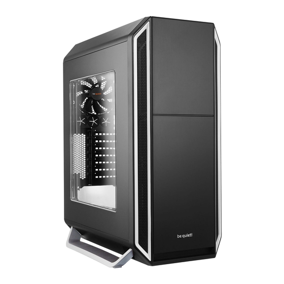
Seite 12: Gehäusebeschreibung
7.2 Gehäusebeschreibung Obere Frontabdeckung Gehäusedeckel Untere Frontabdeckung Front I/O-Anschlüsse Front-Luftfilter Montage Zusatzlüfter Ansauglüfter Abluftventilator 5�25” Schächte/Blenden Verriegelung 5.25” Laufwerk Linkes Seitenpanel mit doppelverglastem Fenster HDD-Käfig (3 Schächte) Belüftungsklappe HDD-Käfig (4 Schächte) Rechte Seitenpanel, Luftfilter PCI-Halterung HINWEIS: rechts keine Montage von Zusatzlüftern möglich! Gehäusefuß... - Seite 13 7.3 Front I/O ports USB 2�0 Kopfhörerbuchse Mikrofonbuchse USB 3�0 Power Knopf/Power LED HDD LED/Reset Knopf 7.4 Die vorhandenen Front I/O-Anschlüsse müssen mit Ihrem Mainboard verbunden werden. HD Audio (Kopfhörer- und Mikrofon-Buchse) Ermitteln Sie die HD Audio Pin-Anschlüsse an Ihrem Mainboard und stecken Sie die HD Audio-Kabel in die dort vorgesehenen Steckplätze.
-
Seite 29: Zainstaluj/Usuń Podstawę Obudowy
STEP-BY-STEP INSTALLATION | SCHRITT-FÜR-SCHRITT ANLEITUNG INSTALLATION - PAS À PAS | INSTALACJA KROK PO KROKU INSTALACIÓN PASO A PASO It is important you follow all the instructions in the sequence they are given� Führen Sie alle beschriebenen Installationsschritte genau in der angegebenen Reihenfolge aus� Il est important de suivre les différentes étapes dans l’ordre suivant. -
Seite 30: Zmiana Kierunku Otwierania Drzwiczek Panelu Przedniego
CHANGING THE DOOR OPENING DIRECTION WECHSELN DES TÜRANSCHLAGS COMMENT MODIFIER LE SENS D’OUVERTURE DES PORTES ? ZMIANA KIERUNKU OTWIERANIA DRZWICZEK PANELU PRZEDNIEGO CAMBIO DE LA DIRECCIÓN DE APERTURA DE LA PUERTA 8.3.1 Remove the rubber caps and release the door stop screws and the two screws on the hinges to remove the upper door. - Seite 31 8.3.3 Remove the front panel. 8.3.3 Entfernen Sie die Frontabdeckung. 8.3.3 Enlevez la façade avant. 8.3.3 Usuń panel przedni. 8.3.3 Retire el panel frontal. 8.3.4 Remove the screws to release the hinge holder. 8.3.4 Entfernen Sie die Schrauben, um die Scharnierhalterung zu lösen.
-
Seite 32: Instalacja Opcjonalnych Wentylatorów/Radiatora
OPTIONAL FANS/RADIATOR INSTALLATION MONTAGE ZUSÄTZLICHER LÜFTER/RADIATOREN COMMENT INSTALLER DES VENTILATEURS OPTIONNELS OU DES RADIATEURS ? INSTALACJA OPCJONALNYCH WENTYLATORÓW/RADIATORA INSTALACIÓN DE VENTILADORES/RADIADORES OPCIONALES 8.4.1 Before removing the upper cover or lower cover, first remove the front panel. 8.4.1 Entfernen Sie immer erst die Frontabdeckung, bevor Sie den Gehäusedeckel oder den Gehäuseboden abnehmen. - Seite 33 8.4.3 The fans/radiator can be adjusted for the top cover. 8.4.3 Die Lüfter/der Radiator können variabel unter dem Gehäusedeckel montiert werden. 8.4.3 Les ventilateurs ou le radiateur peuvent être ajustés latéralement. 8.4.3 Położenie wentylatorów/radiatora może być regulowane w panelu górnym. 8.4.3 El ventilador/radiador se puede ajustar a la cubierta superior.
-
Seite 34: Instalacja Płyty Głównej
8.4.6 To mount a radiator at the front, HDD cages have to be removed. 8.4.6 Für den Einbau eines Radiators im vorderen Bereich müssen die HDD-Käfige entfernt werden. 8.4.6 Pour monter un radiateur dans la partie avant du boîtier, les racks HDD doivent être retirés. 8.4.6 W celu instalacji wentylatora z przodu obudowy, usuń... -
Seite 35: Comment Installer L'alimentation
INSTALLATION OF POWER SUPPLY UNIT Insert the power supply unit at the bottom of the case, secure the PSU with screws� EINBAU DES NETZTEILS Setzen Sie das Netzteil in den Boden des Gehäuses ein� Sichern Sie das Netzteil anschließend mit den beigelegten #6-32 Sechskantschrauben. -
Seite 36: Comment Installer Les Périphériques 3�5"/Hdd
8.7.2 Slide the 5.25” device/ODD into the drive bay. Push the lock backwards to secure it. An extra screw ensures it remains locked. 8.7.2 Schieben Sie das 5.25” Laufwerk/ODD in den Schacht. Drücken Sie das Laufwerk nach hinten, damit die Verriegelung einrastet. Zur Sicherheit befestigen Sie das Laufwerk mit den beigelegten Schrauben. -
Seite 37: Comment Installer Le Rack Disque Dur 3 Baies Dans La Baie 5,25
8.8.2 Open the gate on the HDD cage. 8.8.2 Öffnen Sie den HDD-Käfig. 8.8.2 Déverrouillez le système de blocage du rack (vis à main en haut=rack ouvert). 8.8.2 Otwórz koszyk na dyski HDD. 8.8.2 Abra la puerta de la caja para discos duros. 8.8.3 Insert the HDD into the HDD cage. - Seite 38 8.9.1 Remove the upper HDD holder by releasing the four screws from the top of the 5.25” bay. 8.9.1 Entfernen Sie die obere HDD-Halterung, indem Sie die vier Schrauben auf dem 5.25” Rahmen lösen. 8.9.1 Retirez la partie supérieure du support de disque dur en libérant les quatre vis du haut de la baie 5.25 ".
-
Seite 39: Comment Installer Des Périphériques 2�5"/Ssd
8.9.3 There are two different positions for the HDD holder: Placed flush with the front or more inwards the case ending behind the 5.25” bezels. 8.9.3 Die HDD-Halterung können Sie so anbringen, dass der HDD Käfig entweder bündig mit der Front abschließt oder hinter den 5.25” Blenden endet. - Seite 40 8.10.1 Mount the 2.5” device/SSD upside down under the top panel of the HDD cage with M3 flat head screws. 8.10.1 Verschrauben Sie das 2.5” Laufwerk/SSD kopfüber mit M3 Flachkopfschrauben von oben im HDD-Käfig. 8.10.1 Montez les périphériques 2,5’’ à l’envers, sous le panneau de la cage, avec les vis à tête plate (M3). 8.10.1 Zamontuj urządzenie 2.5”/SSD do góry nogami pod górnym panelem koszyka HDD i zamocuj śrubkami płaskimi M3.
-
Seite 41: Comment Nettoyer Les Filtres
8.10.2 To mount the 2.5” device/SSD behind the motherboard tray: Remove the 2.5” device/ SSD tray from the rear of the motherboard tray. Secure the SSD with M3 flat head screws. 8.10.2 Um das 2.5” Laufwerk/SSD hinter dem Mainboardschlitten zu montieren, entfernen Sie den 2.5”... -
Seite 42: Démontage De La Fenêtre Intérieure Du Panneau Latéral
8.11.2 For the air filter on the side panel, pull out the side panel cover to access the air filter. 8.11.2 An den Luftfilter in der Seitenabdeckung gelangen Sie, indem Sie die Belüftungsklappe herausnehmen. 8.11.2 Pour accéder aux filtres à poussière latéraux, retirez les couvercles des panneaux latéraux.