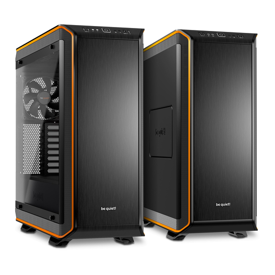
BE QUIET! Dark Base 900 Benutzerhandbuch
Vorschau ausblenden
Andere Handbücher für Dark Base 900:
- Bedienungsanleitung (78 Seiten) ,
- Bedienungsanleitung (78 Seiten)
Inhaltsverzeichnis
Verfügbare Sprachen
Verfügbare Sprachen
Inhaltsverzeichnis

Verwandte Anleitungen für BE QUIET! Dark Base 900


Inhaltszusammenfassung für BE QUIET! Dark Base 900
-
Seite 2: Inhaltsverzeichnis
INDEX Glinde, April 2016 ENGLISH » 1. INTRODUCTION ............................2. SPECIFICATIONS ............................3. CONTENTS ..............................4. EXPLODED VIEW & PARTS .......................... 5. LAYOUTS..............................6. FAN COMPATIBILITY ........................... RADIATOR SUPPORT ..........................8. REMOVE EXTERNAL PARTS ........................9. INSTALLATION AND REMOVAL OF DRIVES AND FILTERS ................10. - Seite 3 9. MONTAGE ET DÉMONTAGE DES DISQUES ET DES FILTRES ..............10. DÉMONTAGE CAGE DISQUE DUR/RÉGLAGE ..................... 11. CHANGEMENT DE CONFIGURATION DU SUPPORT DE CARTE MÈRE ............12. DÉPLACEMENT DE L’ALIMENTATION ......................13. RÉGLAGE DE LA PORTE ..........................14. INSTALLATION DES COMPOSANTS ......................LIMITED WARRANTY ............................
-
Seite 12: Einleitung
EINLEITUNG Wir freuen uns, dass Sie sich für das be quiet! Gehäuse Dark Base entschieden haben. Bitte lesen Sie vor Inbetriebnahme die nachstehenden Informationen aufmerksam durch und beachten Sie die einzelnen Installationshinweise. Bei weiteren Fragen wenden Sie sich gern an unseren Kundenservice. Die Kontaktdaten finden Sie im Abschnitt „Herstellerangaben“. -
Seite 13: Spezifikationen
2 x USB 3.0, 2 x USB 2.0, HD Audio Buchse Lüftersteuerung Dark Base 900: 3x 4-Pin, 3x 3-Pin, Steuerung: manuell 5V-12V Dark Base Pro 900: 4x 4-Pin, 4x 3-Pin, Steuerung: manuell 5V-12V / PWM hub Max. Höhe CPU-Kühler (mm) Max. Länge Grafikkarte (mm) -
Seite 14: Lieferumfang
LIEFERUMFANG Abbildung Bezeichnung Anzahl Verwendungszweck Befestigungspunkt für z.B. LCS Halterung Wasserpumpen o.ä. Befestigung des dritten Lüfters an der Halterung für den oberen Lüfter Front HDD 6#32 Schrauben Anbringung der HDD-Slots M3 Schrauben SSD-Befestigung Schrauben 6#32 Mainboard-Befestigung Stand Off Schraube 14.4mm E-ATX Befestigung Rändelschrauben M3 ODD-Befestigung Kabelbinder Kabelmanagement... -
Seite 15: Explosionszeichnung & Teile
EXPLOSIONSZEICHNUNG & TEILE DARK BASE PRO 900 Seitenabdeckung aus Temperglas Äußere Bodenabdeckung Befestigungsschrauben SilentWings 3 Lüfter ® HDD-Panel MB-Tray HDD-Slots SSD-Halterung Netzteilhalterung Lüftersteuerungs-Platine Abdeckung Rückseite Äußere Frontabdeckung Halterung Power Adapter ODD-Blende ODD-Käfig Luftfilter vorne Gehäuse Frontpanel Äußere Abdeckung Oberseite Seitenteil Front I/O-Panel Filter im Seitenteil Luftfilter Boden 2-stufige Öffnung im Seitenteil... - Seite 16 DARK BASE 900 2-stufige Öffnung im Seitenteil Luftfilter Boden Filter im Seitenteil Äußere Bodenabdeckung Seitenteil SilentWings 3 Lüfter ® HDD-Panel M/B-Tray HDD-Slots SSD-Halterung Netzteilhalterung Lüftersteuerungs-Platine Abdeckung Rückseite Äußere Frontabdeckung Netzteilhalterung ODD-Blende ODD-Käfig Luftfilter vorne Gehäuse Frontseite Äußere Abdeckung Oberseite Front I/O-Panel...
-
Seite 17: Front I/O Und Media Anschlüsse
4.1 FRONT I/O UND MEDIA ANSCHLÜSSE DARK BASE PRO 900 DARK BASE 900 USB 3.0 USB 2.0 LED-Schalter (Pro Version) Kopfhörer Mikrofon Qi Ladestation (Pro Version) An-/Aus-Schalter / LED Reset HDD LED Lüftersteuerungs-Schieberegler 4.2 I/O ANSCHLÜSSE Die vorhandenen Front I/O-Anschlüsse müssen mit Ihrem Mainboard verbunden werden. -
Seite 18: Pcb Panel / Anschlüsse
4.3 PCB PANEL / ANSCHLÜSSE DARK BASE 900 DARK BASE PRO 900 4-Pin PWM Verbindungsstecker zum 4-Pin PWM Verbindungsstecker Mainboard 4-Pin PWM Verbindungsstecker 3-Pin Lüfter Verbindungsstecker 3-Pin Lüfter Verbindungsstecker Anschluss für Lüftersteuerungs- Schieberegler LED-Leiste Verbindungsstecker Power Connector (SATA) Power Connector (SATA) Anschluss für Lüftersteuerungs-Schieberegler... -
Seite 19: Installation Und Handhabung Der Leds (Nur Pro-Version)
PWM-Anschluss auf Ihrem MB verbunden werden. Ohne diese Verbindung kann die Geschwindigkeit der angeschlossenen Lüfter ausschließlich manuell gesteuert werden. DARK BASE 900 Keine automatische Steuerung vorhanden. Die Geschwindigkeit aller am PCB Panel (4.3) angeschlossenen Lüfter (PWM und 3-Pin) wird manuell über den Schieberegler der Lüftersteuerung geregelt. - Seite 45 7x PCI Slots / Space above M/B: 62mm 7x PCI-Anschlüsse / Platz über M/B: 62mm 7x Emplacements PCI / Espace au-dessus de la carte mère : 62 mm 7x sloty PCI / Przestrzeń nad M/B: 62mm 7x ranuras PCI / Espacio por encima del módulo M/B: 62 mm 6x PCI Slots / Space above M/B: 84mm 6x PCI-Anschlüsse / Platz über M/B: 84mm 6x Emplacements PCI / Espace au-dessus de la carte mère : 84 mm 6x sloty PCI / Przestrzeń nad M/B: 84mm 6x ranuras PCI / Espacio por encima del módulo M/B: 84 mm...
- Seite 46 7x PCI Slots / Space above M/B: 77mm 7x PCI-Anschlüsse / Platz über M/B: 77mm 7x Emplacements PCI / Espace au-dessus de la carte mère : 77 mm 7x sloty PCI / Przestrzeń nad M/B: 77mm 7x ranuras PCI / Espacio por encima del módulo M/B: 77 mm 6x PCI Slots / Space above M/B: 99mm 6x PCI-Anschlüsse / Platz über M/B: 99mm 6x Emplacements PCI / Espace au-dessus de la carte mère : 99 mm 6x gniazdo PCI / Przestrzeń nad M/B: 99mm 6x ranuras PCI / Espacio por encima del módulo M/B: 99 mm...
-
Seite 48: Remove External Parts
8.1 SIDE PANEL REMOVAL / ENTFERNEN DER SEITENABDECKUNG / DÉMONTAGE PANNEAU LATÉRAL / DEMONTAŻ PANELU BOCZNEGO / DESMONTE DEL PANEL LATERAL Dark Base Pro 900 Dark Base 900 Remove the thumb screw nuts to remove glass Loosen the thumb screws to remove the steel... - Seite 49 8.2 TOP COVER REMOVAL / ENTFERNEN DER OBEREN ABDECKUNG / DÉMONTAGE DU PANNEAU SUPÉRIEUR / ZDEJMOWANIE POKRYWY GÓRNEJ / DESMONTE DE LA TAPA SUPERIOR Frist remove the front panel (8.3). Locate the 8 Lift the top cover to remove hooks under the top cover and push them outwards Heben Sie den Deckel an, um ihn zu entfernen to free the top cover Soulevez le panneau pour le retirer...
- Seite 50 Open the front panel door and first remove the Release the hooks to free the front panel base air filter Lösen Sie die Häkchen, um die Vorderseite zu Öffnen Sie die Tür der Vorderseite und entfernen entfernen Sie als erstes den Luftfilter am Boden Actionnez les crochets pour libérer le panneau Ouvrez la porte et retirez le filtre à poussière du bas avant Otwórz drzwiczki panelu przedniego i najpierw Zwolnij zaczepy, by odblokować panel przedni wyjmij filtr przeciwkurzowy na dole obudowy Libere los ganchos para soltar el panel frontal Abra la puerta del panel frontal y retire primero el filtro de aire de la base Pull the front panel to release...
-
Seite 51: Installation And Removal Of Drives And Filters
To detach the stand, release the hooks, and push out the stand from the lower cover Um die Standfüße zu entfernen, lösen Sie die Schrauben und drücken Sie die Standfüße nach un- ten heraus. Pour détacher le support, libérez les crochets et retirez le support Aby odłączyć nóżki, zwolnij zaczepy i wypchnij nóżki z dolnej pokrywy... - Seite 52 9.2 ODD CAGE REMOVAL / ENTFERNEN EINES ODD-KÄFIGS / DÉMONTAGE CAGE LECTEUR OPTIQUE / DEMONTAŻ KOSZYKA ODD / DESMONTE DE LA CAJA DE DISPOSITIVOS ODD Remove the front I/O module and screws to Install the Upper Fan Bracket for an additional release the ODD cage front intake fan Entfernen Sie das vordere I/O Modul und die...
- Seite 53 9.4 HDD RUBBER GROMMETS / HDD GUMMISCHEIBEN / PATINS EN CAOUCHOUC POUR DISQUE DUR / GUMOWE PRZELOTKI HDD / OJALES DE GOMA PARA DISPOSITIVOS HDD Rubber grommets can be fitted to use the HDD bay as a cable management opening Die mitgelieferten Gummidurchführungen eignen sich, um HDD-Slots als eine Öffnung für das Kabel- management zu nutzen Des patins en caoutchouc peuvent être installés afin de faciliter le rangement des câbles...
-
Seite 54: Hdd Panel Removal / Adjustment
9.6 AIR FILTER REMOVAL / ENTFERNEN DES LUFTFILTERS / DÉMONTAGE DES FILTRES A POUSSIÈRE / DEMONTAŻ FILTRÓW PRZECIWKURZOWYCH / DESMONTE DE FILTROS DE AIRE Pull out the base air filter and front filters to Release the air filter from the side panel remove Entfernen Sie den Luftfilter vom Seitenteil Ziehen Sie den unteren und die vorderen Filtern Retrait du filtre à poussière latéral heraus Zdejmij filtr przeciwkurzowy z panelu bocznego... - Seite 55 Release the HDD panel by undoing the screws Lösen Sie den HDD-Panel ab, indem Sie die Schrauben lösen Libérez le panneau HDD en dévissant les vis Zwolnij panel HDD poprzez odkręcenie śrubek Suele el panel para la unidad HDD aflojando los tornillos Rotate the HDD panel 180 degrees Drehen Sie den HDD-Panel um 180 Grad Retournez le panneau à...
-
Seite 56: Mb-Tray Layout Adjustment
Install the HDD panel on the opposite side of the case Installieren Sie den HDD-Panel auf der ge- genüberliegenden Seite des Gehäuses Installez le panneau HDD de l’autre côté du boîtier Zainstaluj panel HDD po przeciwnej stronie obu- dowy Instale el panel de la unidad HDD en el lado opuesto de la caja Remove the rubber grommets from the rear panel brackets and re-install them on the opposite... - Seite 57 Mounting points on the front side of the M/B tray Befestigungspunkte auf der Vorderseite des M/B-Trays Points de fixation à l’avant du plateau Punkty montażowe z przodu tacki płyty głównej Puntos de montaje en la cara delantera de la bandeja de la placa base Mounting points on chassis, three steps of ad- justment up and down Befestigungspunkte am Gehäuse;...
- Seite 58 The M/B tray can act as a test bench Der M/B-Tray kann als Test-Bench genutzt werden Le plateau de la carte mère peut être utilisé comme table de bench Tacka płyty głównej może także służyć jako pod- stawka do testów systemu(test bench) La bandeja de la placa base se puede actuar como base para realizar pruebas de dispositivos Adjust the M/B position and re-secure the M/B tray...
-
Seite 59: Psu Layout Adjustment
To swap the M/B to other side of the case both the HDD panel and power supply bracket need to be relocated. We recommend removal of the M/B tray, HDD panel, ODD cage, and PSU brackets if you want to change the layout Um das Mainboard auf der anderen Seite des Gehäuses zu installieren, müssen das HDD-Panel und auch die Halterung des Netzteils versetzt... - Seite 60 Remove the PSU bracket and swap the step screws on the base as in diagrams P1 to P4 Entfernen Sie die PSU-Halterung und reposition- ieren Sie die Step-Schrauben am Boden wie in den Diagrammen P1 – P4 Retirez le support de l’alimentation et installez les dans les trous indiqués dans les diagrammes P1 à...
- Seite 61 P2 for M/B layout A3, A4, A5, A6 Step screw mounting points Befestigungspunkte der Step-Schrauben Détail des points de fixation Wybierz następujące punkty montażowe śrubek Puntos de montaje de tornillos de paso P3 for M/B layout A1, A2, B1, B2 Step screw mounting points Befestigungspunkte der Step-Schrauben Détail des points de fixation Wybierz następujące punkty...
-
Seite 62: Door Panel Adjustment
DOOR PANEL ADJUSTMENT | EINSTELLUNG FRONTSEITE RÉGLAGE DE LA PORTE | DOSTOSOWANIE POŁOŻENIA DRZWICZEK AJUSTE DEL PANEL DE LA PUERTA Remove the door panel from the front panel Remove all the hinges and magnet holders Entfernen Sie das Frontpanel vom Gehäuse Entfernen Sie alle Scharniere und Magnethalter Retirez la porte Retirez les charnières et les aimants... -
Seite 63: Component Installation
Re-install the hinges and magnet holders to the Re-install the door panel in the front panel opposite side of the door panel Installieren Sie die Türverkleidung wieder an der Verschrauben Sie alle Scharniere und Mag- Front nethalter auf der gegenüberliegenden Seite Refixez la porte sur le châssis Réinstallez les charnières et les aimants de Zainstaluj drzwiczki w panel przednim... - Seite 64 14.2 POWER SUPPLY (PSU) INSTALLATION / NETZTEIL (PSU) INSTALLATION / MONTAGE DE L’ALIMENTATION / INSTALACJA ZASILACZA (PSU) / INSTALACIÓN DE LA FUENTE DE ALIMENTACIÓN (PSU) Remove the screws to detach the PSU mount- ing bracket Lösen Sie die Schrauben um die PSU-Montage- halterung zu entfernen Retirez les vis pour détacher le support de mon- tage...
- Seite 65 14.3 PCI/PCI-E ADD-ON CARD INSTALLATION / PCI/PCI-E ADD-ON CARD INSTALLATION / MONTAGE DES CARTES D’EXTENSION PCI/PCI-E / DODATKOWA INSTALACJA KART PCI / PCI-E / INSTALACIÓN DE TARJETAS PCI / PCI-E MODULARES Remove the PCI slot bracket before installing a PCI / PCI-E add-on card Entfernen Sie die PCI-Slot-Abdeckung bevor Sie mit der Installation einer PCI / PCI-E Add-on-Card beginnen...
- Seite 66 Fit the pump to the WCS bracket with rubber grommets (screws and nuts are not included) Setzen Sie die Pumpe auf die WCS-Halterung. Zur Entkoppelung nutzen Sie die mitgelieferten Gummitüllen. (Schrauben und Muttern sind nicht enthalten) Placez la pompe sur le support, avec des patins en caoutchouc (vis et écrous non fournis) Umieść pompę chłodzenia wodnego w uchwy- cie WCS za pomocą gumowych uchwytów (śrubki i...