Hitachi D-E2 U Serviceanleitung
@HITACHI
SERVICE
NOTE:
The Dolby
NR IC in units having a Manufacturer's
No. from
3002041 —3013650,
a different
specification.
Along with this difference,
the
associated
circuit
arrangement
careful
to
check
the
Manufacturer's
repairing.
HINWEIS:
Der in Einheiten
mit der HersteIIungs-Nr.
—3013650,
3017561
eingebaute Dolby-Rauschunter-
drückungs-lC
weist
abweichende
auf.
Einer
dieser
Unterschiede
anderen Anordnung
der dazugehörigen
Bei der Reparatur
deher unbedingt
Nr.
kontrollieren.
REMARQUE:
Le circuit
intégré du réducteur
équipe Ies appareils portant un NOde fabrication
partir de 3002041&3013650,
posséde une spécification
difference,
noter
que
I'arrangement
associés est également
différent.
NO de fabrication avant de procéder ä une réparation.
CONTENTS
SPECIFICATIONS
.
FEATURES
.
DISASSEMBLY
ADJUSTMENTS
PRINTED
WIRING
BOARD
CIRCUIT
DIAGRAM
BLOCK
DIAGRAM
LUBRICATION
EXPLODED
VIEW.
REPLACEMENT
PARTS
LIST
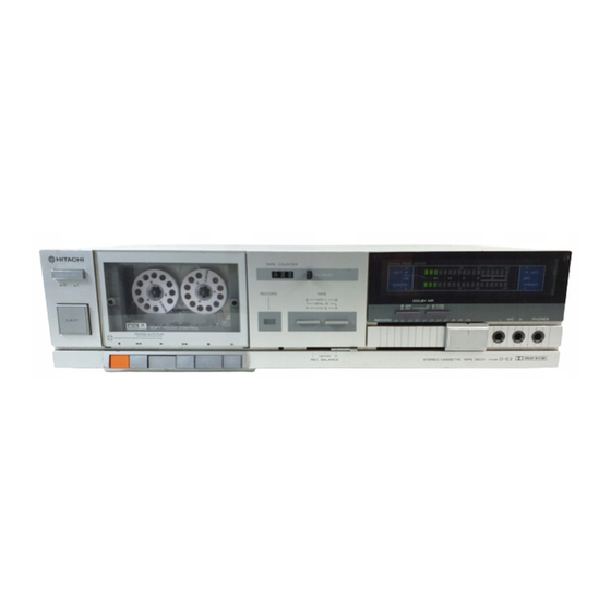
KEY
TO
ILLUSTRATIONS
O
POWER
STAND-BY
EJECT
BUTTON
3
RECORD
BUTTON
REWIND
BUTTON
4
PLAYBACK
BUTTON
5
FAST
FORWARD
BUTTON
O
STOP
BUTTON
8
PAUSE
BUTTON
9
RECORDING
INDICATOR
TAPE
SELECT
SWITCHES
O
RECORDING
BALANCE
O
RECORDING
LEVEL
DOLBY
NR
SWITCH
DOLBY
BIC
NR
SELECT
MICROPHONE
JACKS
HEADPHONE
JACK
LEVEL
METERS
TAPE
COUNTER/RESET
O
CASSETTE
HOLDER
SPECIFICATIONS
STEREO CASSETTE
August
MANUAL
3017561
onward has
is different.
Be
No.
when
ab3002041
Spezifikationen
besteht
in
einer
Schaltkreise.
die Herstellungs-
de bruit
Dolby qui
3017561 et au-delå
différente.
Outre cette
des circuits
Veiller
vérifier
Ia
INHALTSVERZEICHNIS
2
TECHNISCHE
3
MERKMALE
4
DEMONTAGE
6
EINSTELLUNGEN
.....
.15
PRINT
PLATTEN
.17
SCHALTPLAN
23
BLOCKSHEMA
. 24
SCHMIERUNG
. 25
EXPLOSIONSANSICHT
ERSATZTEILLISTE
. .
. 27
Regler und Bedienungselemente
SWITCH
Netz/Bereitschafts-SchaIter
Aumurfaste
3
Aufnahmetaste
4
Rück lauftaste
5
Weidergabetaste
6
Schnellvorlauftaste
7
Stoptaste
Pausetaste
Aufnahmeanzeige
Bandsortenwähler
CONTROL
Aufnahme-BaIanceregIer
CONTROL
Aufnahmepegelregler
Dolby • -N R-Schalter
SWITCH
Dolby-B/C.NR-Wahlschalter
Mikrofonbuchsen
Kopfhörerbuchse
Pegelmesser
BUTTON
Bandzählwerk/Rückstelltaste
Cassettenhalter
AND
PARTS
ARE
1983
TY
ozo
6
8
5
7
DATEN
.
.15
.
.17
. 23
.
. 24
..
. 25
.
. 27
SUBJECT
TO
CHANGE
TAPE DECK
TOYOKAWA
No.
368EGF
D-E2
9
TABLE
DES
MATIERES
2
FICHE
TECHNIQUE
CARACTERISTIQUES
DÉMONTAGE
4
RÉGLAGE
.
9
PLAN
DE BASE
.....
PLAN
DE CIRCUIT
SCHEMA
LUBRIFICATION
VUE EXPLOSÉE.
...
TABLEAU DES PIECES
Guide
des illustrations
Interrupteur stand-by (attente) d'alimentation
2
Touche d'éjection
3
Touche d'enregistrement
4
Touche
de
Touche
de lecture
6
Touche d'avance rapide
7
Touche
d'arrét
Touche
de pause
9
Témoin d'enregistrement
Sélecteurs
de bande
de balance å I'enregistrement
Commande
de niveau d'enregistrement
Interrupteur
de Dolby*
Sélecteur Dolby B/C NR
Prises de microphone
Prise de casque d'écoute
Indicateurs
de niveau
Touche de compteur
de repérage/remise
sur zéro
Trappe å cassette
FOR
IMPROVEMENT.
WORKS
3
. 12
.....
...
.15
.17
. 23
. 24
. 25
. 27
NR
Inhaltsverzeichnis

Verwandte Anleitungen für Hitachi D-E2 U


Inhaltszusammenfassung für Hitachi D-E2 U
- Seite 1 @HITACHI 368EGF D-E2 SERVICE MANUAL NOTE: The Dolby NR IC in units having a Manufacturer's No. from 3002041 —3013650, 3017561 onward has a different specification. Along with this difference, associated circuit arrangement is different. careful check Manufacturer's when repairing. HINWEIS: Der in Einheiten mit der HersteIIungs-Nr.
- Seite 2 SAFETY PRECAUTIONS The following precautions should be Obwrved when servicing. 1. Since many parts in the unit have special safety related characteristics. always use genuine Hitachi's replacement parts. Especially critical parts in the pomr circuit block should not be replaced with other makers.
- Seite 3 Composants de I'appareil possédent des caractéristiques relatives la sécurité. utiliser uniquement piéces de rechange d'origine Hitachi pour effectuer un remplacement. Ceci se rapporte notamment aux piéces critiques du bloc d'alimentation qui ne doivent en aucun cas étre remplacées par celles d'autres fabricants.
- Seite 4 D-E2 DISASSEMBLY LED meter (Fig. 4) I. Cassette Lid (Fig. I) Open cassette lid and remove nylon rivets. Disengage nails to remove LED meter attachment. 2. Top Cover (Fig. 2) Main P.W. Board (Fig. 5) Remove two screw O Remove front panel.
- Seite 5 D-E2 meter attachment meter P.W.B LED-Meßinstrument LE D -Meßinstrument-l-eiterplatte Piéce de fixation décibelmétre Plaquette de Cl du décibelmétre Cassette å LED Cassettenfachdeckel Couvercle du logement de la cassette Nylon rivets Nylonniete nails Rivets en nylon Zwei Nägel Deux clous Fig. 1 Abb.
-
Seite 6: Adjustment
(for tape run check) Tape Speed Adjustment NORMAL alignment tape (UD tape) Adjustment CHROME alignment tape (EX tape) Input Adjustment point value HITACHI METAL tape (ME tape) Tape speed Semi-fixed volume 3,000 adjustment tape —10 inside Of the motor... - Seite 7 Normal within ± 1 .OdB Check OdB — 20dB 1k/10k tape Ch rome cr02 within ±3dB Check 1k/10k OdB — 20dB tape HITACHI METAL METAL within ±3dB Check OdB — 20dB 1k/10k tape Adjustment Procedure Bias Current Adjustment Then, adjust...
- Seite 8 D-E2 5. Dolby NR operation check check that output difference between frequencies is within ±0.5 • Dolby B type 4) When the output difference is out of ±0.5 dB range, Record using metal tape C46) 5 kHz, adjust R408L, R properly and repeat recording/ —40 dB with...
- Seite 9 NORMAL-Abgleichband (UD Band) I. Einstellung der Bandgeschwindigkeit lung 7. CHROME-Abgleichband (EX Band) Normal- Innerhalb E ingang Einstellwert Einstellpunkt OdB — 20dB R408L, HITACHI METAL-Band (ME Band) 1k/10k band Bandgeschwindig- 3.000 + %Hz Halbfester Pegel keit-EinsteIIband Motor Normal- Innerhalb • Positionen der Reglet —16dBm...
- Seite 10 Spannung der Aufwickelseite Ohne Zählwerk g•cm réglage de vitesse 3.000 å I'intérieur —10 10 g•cm Oder mehr Bremsmoment bande Bande HITACHI METAL (bande moteur Achsenspiel des Schwungrades 0,05 Abb. Positions des boutons Méthode de réglage A moins d'indication contraire, régler les commutateurs...
- Seite 11 ±3dB Vérification — 20dB ch rome Bande métal METAL OdB — 20dB moins de ±3dB Vérification 1k/10k HITACHI Méthode de réglage Réglage du courant de polarisation que l'indicateur indique O dB. 1) Raccorder un oscillateur audio aux bornes LINE Puis régler I'atténuateur...
- Seite 12 * : Axial lead cylindrical ceramic capacitor. PRINTED WIRING BOARD (Before Change)• PRINTPLATTEN (Vor Änderung) • PLAN DE BASE (Avant Changement) * : Zylindrischer Keramikkondensatormit axialer Zuleitung. * : Condensateur céramique cylindrique å conducteur axial. : Otherl 3000001 - 3002040, 3013651 — 3017560 WHITE SWITC OUTPUT...
- Seite 13 CAUTION Axial lead cylindrical ceramic capacitor. CIRCUIT DIAGRAM (Before Change) • SCHALTPLAN (Vor Änderung) Use the electrolytic capacitors with explosion-proof valve Zvlindrischer Keramikkondensator mit axialer Zuleitung. when the diameter of them is more than 10 mrnØ PLAN CIRCUIT (Avant changement) Condensateur céramique cylindrique...
-
Seite 14: Power Supply
D-E2 D-E2 PRINTED WIRING BOARD (After Change) • PRINTPLATTEN (Nach Anderung) Axial lead cylindrical ceramic capacitor. x : Zylindrischer Keramikkondensator mit axialer Zuleitung. PLAN DE BASE (Aprés changement) 3002041 — 3013650, 3017561 — • Condensateur ceramique cylindrique a conducteur axial. —... -
Seite 15: Schaltplan
D-E2 Axial lead cylindrical ceramic capacitor. CIRCUIT DIAGRAM (After Change) • SCHALTPLAN (Nach Änderung) CAUTION electrolytic capacitors with explosion-proof Valve : Zylindrischer Keramikkondensator mit axialer Zuleitung. PLAN CIRCUIT (Apres changement) when diameter them is more than 10 mrn+ : Condensateur ceramique cylindrique a conducteur... - Seite 16 D-E2 D-E2 DIAGRAM • BLOCKSCHEMA • SCHÉMA BLOCK LUBRICATION Metal to metal Pan motor oil (IOW-40) Rotating parts Plastics to metal Sonic slider oil (#1600) Apply one or two drops of pan motor Oil or sonic slider oil (Before Change .
-
Seite 17: Explosionsansicht
D-E2 EXPLODED VIEW (Cabinet) • EXPLOSIONSANSICHT (Chassis) • VUE EXPLOSEE (Coffret) —25—... - Seite 18 D-E2 EXPLODED VIEW (Cassette Chassis) • EXPLOSIONSANSICHT (Chassetten Tonbandgerät) • EXPLOSEE (Maqnétphone)
-
Seite 19: Ersatzteilliste
D-E2 PIECES LIST • ERSATZTEILLISTE • TABLEAU REPLACEMENT PARTS CABINET CHASSIS ITEM PART ITEM SYMBOL PART DESCRIPTION DESCRIPTION 4088743 Chassis ass'y (for U) 3296701 Eject lever 4088741 Chassis ass'y (for C, VK, BS, SA) Eject spring 3362631 4088742 LED Pannel Chassis ass'Y (for W) 3958141 4449921... - Seite 20 D-E2 LIST (Before Change) • ERSATZTEILLISTE (Vor Änderung) REPLACEMENT PARTS TABLEAU DES PIECES (Avant changement) 3000001 — 3002040, 3013651 — 3017560 SYMBOL PART SYMBOL PART DESCRIPTION DESCRIvr10N 1 ov C608 0252325 Electrolytic 47gF CAPACITORS Cylindrical ceramic 6800pF RESISTORS 0240105 0252521 Electrolytic 1/4 p 0129639...
- Seite 21 D-E2 LIST (After Change) • ERSATZTEILLISTE (Nach Änderung) REPLACEMENT PARTS TABLEAU PIECES (Apres changement) SYMBOL PART SYMBOL PART SYMBOL PART SYMBOL PART DESCRIITION DESCRIPTION DESCRIPTION DESCRIPTION 0252803 Electrolytic 0.33ßF SEL1413E CAPACITORS C910 0129673 Carbon film 330kS2 LED251 2339891 R318 C911 0252811 Electrolytic Carbon...
- Seite 22 D-E2 D-E2 SYMBOL PART SYMBOL PART SYMBOL SYMBOL PART PART DESCRIPTION DESCRIPTION DESCRIvr10N DESCRIPTION Carbon film 5.6k0 SRD 1/4P 2387291 IR2E25 1-901 2227355 Choke coil 2639151 Push switch (STOP MUTE) R252 0129619 IC251L,R 2639152 Push switch (REV. CUE MUTE) R253 0129631 Carbon film...
- Seite 23 D-E2 MEMO —33—...
- Seite 24 @HITACHI HITACHI SALES CORPORATION AMERICA HITACHI SALES NORWAY Eastern Regional Office Oerebekk 1620 Gressvik P.o. Box 46N-1601 1200 Wall Street West, Lyndhurst, New Jersey Fredrikstad, Norway 07071, U.S.A. Tel. 032-28255 Tel. 201-935-8980 SUOMEN HITACHI Mid-Western Regional Office Takojankatsu 5, 15800 Lahti 80, Finland 1400 Morse Ave., Elk Grove Village,...