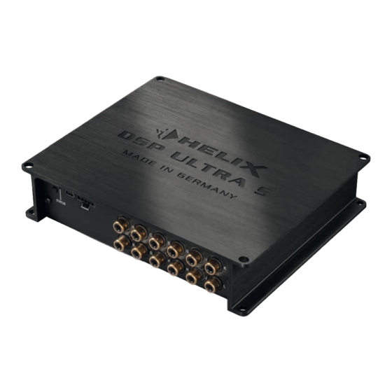
Inhaltszusammenfassung für HELIX DSP ULTRA S
- Seite 1 DSP ULTRA S High-Res 12-Kanal DSP High-Res 12-channel DSP User Manual Bedienungsanleitung...
-
Seite 3: Allgemeine Hinweise
Audiotec Fischer setzt HELIX überzeugende Anwendung ausgereifter Technolo- DSP ULTRA S neue Maßstäbe im Bereich der gien aus. Signalprozessortechnik. Dabei profitieren Sie als Kunde direkt von unserer mehr als 30-jährigen Viel Freude an diesem Produkt wünscht Ihnen das Erfahrung in der Forschung und Entwicklung von Team von Audiokomponenten. -
Seite 4: Anschluss- Und Bedienelemente
Anschluss- und Bedienelemente Lowlevel-Vorverstärkereingänge Control Taster Seite 5, Punkt 2 Seite 10, Punkt 2 Digitaleingänge (Coaxial & Optical) USB Eingang Seite 6, Punkt 4 Seite 7, Punkt 7 Clipping LED SCP (Smart Control Port) Seite 10, Punkt 1 Seite 10, Punkt 4 Auto Remote-Schalter Vorverstärkerausgänge Seite 6, Punkt 5... -
Seite 5: Hardware-Konfiguration
Hardware-Konfiguration Konfigurieren Sie den HELIX DSP ULTRA S in c. „Load Jumper“ entfernen / gesteckt las- der nachfolgenden Reihenfolge Zum Entfernen ziehen sie den Jumper ein- Achtung: Für die Durchführung der nachfol- fach nach oben hin ab, siehe Abbildung 2. - Seite 6 üblicherweise nicht lautstärkegeregelt. ßen, empfehlen wir folgende Kanalbelegung: Das bedeutet, dass an den Signalausgängen des HELIX DSP ULTRA S der volle Pegel an- Kanal A = Vorne links Kanal B = Vorne rechts liegt und die angeschlossenen Verstärker voll ausgesteuert werden.
- Seite 7 –: Anschluss für die Masseleitung. Das Mas- Mit Hilfe des USB Eingangs kann der sekabel muss an einer nicht isolierten Stelle DSP ULTRA S über das beiliegende Kabel mit mit dem Kfz-Chassis verbunden werden. Der dem Computer verbunden und anschließend Kabelquerschnitt sollte den gleichen Durch- über das DSP PC-Tool konfiguriert werden.
- Seite 8 USB-Verlängerung mit integrier- Sollte die Signalquelle eine niedrigere Aus- tem Repeater. gangsspannung liefern, kann die Eingangs- 3. Schalten Sie erst den DSP ULTRA S ein empfindlichkeit stufenlos angehoben werden. und starten Sie anschließend die Software. Sofern Ihre Signalquelle eine höhere Aus-...
- Seite 9 DSP PC-Tool Software frei konfigurieren. 13. Optional: Konfiguration der Masseanbin- dung Nützliche Hinweise zur korrekten Einstellung Beim HELIX DSP ULTRA S ist die Signalmas- entnehmen Sie unserer Knowledge Base, se galvanisch von der Bordnetzmasse ge- welche auf unserer Webseite bereit steht.
- Seite 10 Sie den Signalprozessor mit der DSP PC-Tool 2. Control Taster Software und bestätigen Sie das automa- Der DSP ULTRA S bietet 10 interne Speicher- tische Update der Betriebssoftware. Die aktu- plätze für Sound Setups. Mit Hilfe des Control ellste Version des DSP PC-Tools finden Sie Tasters lässt sich zwischen zwei Speicher-...
- Seite 11 5. Masseschalter Beim HELIX DSP ULTRA S ist die Signal- masse galvanisch von der Bordnetzmasse getrennt. Dies ist in den meisten Fahrzeugen die beste Option, um Störgeräusche wie z.B. von der Lichtmaschine zu unterbinden. Aller- dings gibt es auch Fälle, wo die Massen der Eingänge mit den Ausgängen direkt „hart“...
- Seite 12 Virtual Channel Processing (VCP) Der HELIX DSP ULTRA S bietet neben dem Standard Routing das Virtual Channel Processing (VCP), ein mehrstufiges Signalverarbeitungs-Konzept, welches die perfekte Konfiguration komplexer Soundsysteme ermöglicht und somit ganz neue Möglichkeiten des Klangtunings eröffnet. Das VCP erweitert den bisherigen Umfang des Gerätes um eine neue Ebene an prozessierten Kanälen, welche sich zwischen den Ein- und Ausgängen befindet.
-
Seite 13: Konfiguration Einer Subwoofer-Fernbedienung
DSP PC-Tool Software aktiviert und je nach Modell konfiguriert werden. Bei nicht aktiviertem VCP ist die Subwoofer-Fernbedienung beim DSP ULTRA S fest den Ausgangs- kanälen K und L (Output Channels) zugeordnet. In diesem Fall ist es nicht entscheidend, welcher Aus- gang in der IO-Routingmatrix mit „Subwoofer“... - Seite 14 ACO Plattform-Features Neben den einzigartigen DSP-Sound effekten bie- Remote Output Configuration tet die ACO-Plattform des DSP ULTRA S zusätz- An dieser Stelle kann festgelegt werden, ob der lich eine Vielzahl an System-Features. Remote-Ausgang, angeschlossenen Im DCM Menü der DSP PC-Tool Software können Verstärker ein- bzw.
-
Seite 15: Einbau Einer Helix Extension Card
Einbau einer HELIX Extension Card Der HELIX DSP ULTRA S kann durch die Monta- 6. Achten Sie auf den richtigen Sitz des HEC ge einer HELIX Extension Card (HEC) um weitere Moduls und darauf, dass alle Kontaktstifte Schnittstellen wie beispielsweise einem High De- vollständig im Sockel stecken. -
Seite 16: Technische Daten
Technische Daten Eingänge ............... 8 x Cinch 8 x Highlevel-Lautsprechereingang 1 x Optisch SPDIF-Format (12 - 96 kHz) 1 x Koaxial SPDIF-Format (12 - 192 kHz) 1 x Remote In Eingangsempfindlichkeit ..........Cinch: 1 - 8 Volt Highlevel: 4 - 32 Volt Ausgänge .............. -
Seite 17: Garantiehinweis
Garantiehinweis Die Garantieleistung entspricht der gesetzlichen Regelung. Von der Garantieleistung ausgeschlossen sind Defekte und Schäden, die durch Überlastung oder unsachgemäße Behandlung entstanden sind. Eine Rücksendung kann nur nach vorheriger Absprache in der Originalverpackung, einer detaillierten Fehlerbeschreibung und einem gültigen Kaufbeleg erfolgen. Technische Änderungen, Druckfehler und Irrtümer vorbehalten! Für Schäden am Fahrzeug oder Gerätedefekte, hervorgerufen durch Bedienungsfehler des Gerätes, können wir keine Haftung übernehmen.


