Herunterladen Inhalt Inhalt Diese Seite drucken
Inhaltsverzeichnis

Werbung

Verfügbare Sprachen

Verfügbare Sprachen

INSTRUCTIONS FOR USE
MODE D'EMPLOI
GEBRAUCHSANWEISUNG
INSTRUCTIONS FOR USE

Werbung

Inhaltsverzeichnis

Fehlerbehebung

loading

Inhaltszusammenfassung für EMS DOLORCLAST

  • Seite 1 INSTRUCTIONS FOR USE MODE D’EMPLOI GEBRAUCHSANWEISUNG INSTRUCTIONS FOR USE...
  • Seite 2 DOLORCLAST RADIAL SHOCK ® WAVES ENGLISH ............... 3 FRANÇAIS ............43 DEUTSCH ............83...
  • Seite 3: Inhaltsverzeichnis

    12. ELECTROMAGNETIC COMPATIBILITY .. 33 3.3. SOFTWARE AND HANDPIECE INFORMATION 13. PRODUCT DISPOSAL ......37 (NUMBERS OF USE)........13 14. EMS TECHNICAL SUPPORT ....37 3.4. SETTING THE LANGUAGE ......13 3.5. STOPPING THE DEVICE ........ 14 15. WARRANTY..........37 4.
  • Seite 4: Please Read This First

    The device is used to treat soft tissue pain near bones, installation and use of this product. Always keep these myofascial pain syndromes, wound healing, lymph- instructions close at hand. edema, and to treat cellulite with the EMS SWISS DOLORCLAST method. ®...
  • Seite 5: Intended Use

    Intended Use Intended User The device has been developed for pain therapy. The The device must be used by qualified health experts (such DOLORCLAST Radial Shock Waves is intended for the ® as doctors and physiotherapists) in hospitals, clinics, application fields described below, provided the affected medical universities and physical therapists’...
  • Seite 6: Potential Complications

    Reddening of the skin. 1. WARNING EMS and the distributor of this product accept no liability for direct or consequential injury or damage resulting from improper use, arising in particular through non-observance of the operating instructions, or improper preparation and maintenance.
  • Seite 7: Installation

    2. INSTALLATION 2.1. COMPONENTS The components provided with your device will vary, according to your configuration. Figure 1 DESIGNATION Console Handpiece with 15-mm applicator (applied part) Applicator set (see details in next page) Cart - Optional Handpiece holder kit Power cord Gel bottle O-ring maintenance kit Piston maintenance kit...
  • Seite 8 15-mm Applicator, Trigger – Optional 15-mm Applicator, Focus – Optional 25-mm Applicator - Optional 5-mm Applicator - Optional *EMS recommends to clean and disinfect the applicator prior to treating a patient. Figure 3 DESIGNATION Connector for the handpiece (applied part)
  • Seite 9: Installing The Console

    2.2. INSTALLING THE CONSOLE 2.2.2. Installing the Handpiece Holder on the Unit Install the console on a flat, stable surface or use 1. Use the screws and tool provided to secure the the cart (optional) designed for the console. handpiece holder to the unit. 2.2.1.
  • Seite 10: Connecting The Console To The Equipotential Conductor

    2. Place the handpiece on the handpiece holder. 2.3. CONNECTING THE CONSOLE TO THE EQUIPOTENTIAL CONDUCTOR When applicable and according to your in-house protocol, connect the equipotential conductor at the rear of the console with the bus bar. The equipotential cable is not supplied with the console.
  • Seite 11: Getting Started

    3. GETTING STARTED 3.1. STARTING THE DEVICE The mains power switch of the product must be accessible at any time, to allow disconnection of the device. 1. Use the mains power switch located on the left side panel to switch on the console. Figure 12 3.2.
  • Seite 12 BUTTON MEANING ACTION Use this button to decrease the value displayed on the Minus button screen. Use this button to increase the value displayed on the 2500 Plus button Impulses screen. SMART PROTOCOL Preset protocol Use these buttons to select a preset protocol. 2500 navigation buttons (See 5.
  • Seite 13: Software And Handpiece Information (Numbers Of Use)

    Figure 16 Changing the language will reset to factory set- tings. If you have saved a USER protocol, it will EMS does not guarantee the performance of the be deleted. treatment if the piston has reached its maximum recommended impulses.
  • Seite 14: Stopping The Device

    4. Press the buttons to select the appro- priate language. Figure 19 5. To display more languages, use the button to view additional language options on subsequent pages. 3.5. STOPPING THE DEVICE 1. Use the mains power switch located on the left side panel to switch off the console Figure 20...
  • Seite 15: Treatment

    ® the handpiece. for best results. Thanks to its special viscosity, the EMS gel transmits shock waves without lea- 7. Position the patient on the treatment bench. king to ensure a perfect transmission throughout 8. Localize the region to be treated by palpation. Find treatment.
  • Seite 16: Adjusting The Frequency

    1. Ensure the O-ring is still in place with the spare appli- 4.2.2. Adjusting the Pressure cator. If the O-ring is disconnected from the applicator, replace it. To adjust the shock wave depth and the energy trans- mitted into the tissue, increase or decrease the pressure. The pressure can be selected between 1 and 4 bar, in increments of 0.1 bar.
  • Seite 17 used for treatment . 2. Select the size of the applicator 4.2.4. Adjusting the Number of Impulses To adjust the total number of impulses transmitted to the patient, increase or decrease the number of impulses. 5 mm 10 mm The number of impulses can be selected between 500 15 mm Trigger 15 mm and 5000, in increments of 500.
  • Seite 18: Performing Treatment

    To maximize treatment efficiency, we recommend holding The QR code of your console screen will lead you the handpiece with two hands, in two different ways: to an EMS website dealing with GDT protocol. • One hand up and one hand down...
  • Seite 19 Figure 37 2. Once you start treatment and as you move the appli- cator around the treatment area, ask the patient to tell you if the treatment becomes uncomfortable and adjust the device settings accordingly. The application force exerted manually varies and depends on the indication.
  • Seite 20: Preset Protocols

    5. PRESET PROTOCOLS 5.1. DESCRIPTION OF PRESET PROTOCOLS You can use preset protocols as a starting point instead of adjusting each setting manually. Preset protocols are available to help you target treatment and increase efficiency. Preset protocols are classified into six families: PRESET PROTOCOLS FACTORY SETTINGS SMART Protocol (Default)
  • Seite 21: Saving Adjusted Preset Protocols

    5.4. SAVING ADJUSTED PRESET PROTOCOLS You can easily save the settings you customized for a given preset protocol. 1. To record the newly customized settings for a given preset protocol, press and hold the buttons simultaneously for 2 seconds. 2500 Impulses ENTHESOPATHY* Figure 40...
  • Seite 22: Special Modes

    6. SPECIAL MODES ANALGESIC [0 mJ/mm Only one special mode can be activated at a time. ANALGESIC [0 mJ/mm All settings associated with the special modes are 1000 preset and cannot be changed. Impulses 1000 Impulses SMART PROTOCOL SMART PROTOCOL 6.1.
  • Seite 23: Ramp-Up Modes

    ANALGESIC [0 mJ/mm ANALGESIC [0 mJ/mm 1000 1000 Impulses Impulses SMART PROTOCOL SMART PROTOCOL Figure 45 1. Before starting treatment or after a pause, press the Ramp-Up button to enable Ramp-Up mode 1. The LED signifies that the mode is enabled. Figure 44 3.
  • Seite 24: Burst Modes

    6.3. BURST MODES Use the Burst modes to prevent the patient from devel- oping tolerance to certain mechanical stimuli. The Burst modes are specifically designed to alternate a preset frequency and a maximum frequency during treatment. 6.3.1. Burst Mode 1 Using Burst mode 1 during treatment will automatically Figure 47 alternate between 4 seconds at the set frequency and...
  • Seite 25 6.3.2. Burst Mode 2 Burst mode 2 makes it possible to manually switch between a set frequency and a frequency of 25Hz. Figure 51 1. Press the Burst button twice to activate Burst mode 2. The LED signifies that the mode is enabled. 1000 Impulses 1000...
  • Seite 26: Cleaning And Disinfecting

    7. CLEANING AND DISINFECTING 1. Disassemble the applicator, the nose, the retaining 7.1. HANDPIECE nut and the o’rings. We advise to clean and disinfect the handpiece after each treatment 1. Clean and Disinfect with a cleaning and disinfectant wipe such as Surface Wipes Zero from Helvemed, or equivalent (quaternary ammonium as active...
  • Seite 27: Maintenance

    Figure 55 The QR code that will appear on your console screen will lead to an EMS website allowing you to order a new piston. To change the piston, proceed as following: Figure 58 1.
  • Seite 28 Pull on the piston to remove it from the handpiece. 5. Install the new piston on the handpiece. 6. Re-assemble the handpiece. 8.1.2. Applicator O-ring EMS recommends to change the o’rings when the piston is changed 8.1.2.1. For 5-mm, 10-mm and 15-mm Applicators 1. Disassemble the applicator.
  • Seite 29 8.1.2.2. For 25-mm and 40-mm Applicators Figure 64 DESIGNATION QUANTITY Figure 68 O-rings Applicator DESIGNATION QUANTITY Nose Nose O-rings Applicator 1. Place the O-ring 1a on the applicator. 2. Place the O-ring 1b on the applicator. 1. Remove the applicator from the handpiece. Figure 65 3.
  • Seite 30 3. Fit the large wrench on the applicator and hold the 6. Remove the nose. support with your hand. Turn the wrench to loosen the nut. Figure 74 Figure 71 7. Remove the second large O-ring. 4. Finish unscrewing the nut manually and remove it from the applicator.
  • Seite 31 9. To assemble the O-rings , place the O-ring on the 12. Place the applicator on the nose. groove of the applicator. Figure 77 Figure 81 Ensure the O-ring is correctly positioned. 13. Place the O-ring on the applicator. Figure 78 Figure 82 10.
  • Seite 32: Console

    5. Insert the fuse drawer. 8.2.1. Replacing Fuses 6. If the fuses fail again, please contact your EMS autho- rized service center. 1. Switch off the device. 2. Disconnect the power cord at the rear of the console.
  • Seite 33: Compatibility With Dolorclast ® Product Range

    Do not change the on the conditions listed by the manufacturer, some actions are required to match those conditions. Please contact the manufacturer. The climatic environmental conditions could affect the life of critical components of the DOLORCLAST Radial Shock ®...
  • Seite 34 Guidance and Manufacturer’s Declaration – Electromagnetic Emissions The DOLORCLAST Radial Shock Waves is intended for use in the electromagnetic environment specified below. ® The customer or the user of the DOLORCLAST Radial Shock Waves should assure that it is used in such an ® environment.
  • Seite 35 Radial Shock Waves should ensure that it is used in such an ® environment. Portable and mobile RF communications equipment should be used no closer to any part of the DOLORCLAST Radial Shock ® Waves, including cables, than the recommended separation distance calculated from the equation applicable to the frequency of the transmitter.
  • Seite 36 28.0 - 29.7 MHz and 50.0 - 54.0 MHz. Table 6 Compliant Cables and Accessories The use of accessories and cables other than those specified or sold by EMS as replacement parts may result in increased emissions or decreased immunity of this product. CABLES AND...
  • Seite 37: Product Disposal

    Please contact your EMS authorized service center for disinfected in accordance with the instruction manual. any product servicing or repairs. You must complete the appropriate EMS form in order to be issued with a Return Repair can be refused for products or accesso- Material Agreement (RMA) number.
  • Seite 38: Technical Description

    16. TECHNICAL DESCRIPTION MANUFACTURER EMS ELECTRO MEDICAL SYSTEMS SA, CH-1260 Nyon, Switzerland MODEL DOLORCLAST Radial Shock Waves ® POWER SUPPLY 100-240 VAC, 50-60 Hz, 500VA CLASSIFICATION EN 60601-1 System: class I Applied part type BF RADIO COMMUNICATION RFID 13.56MHz , < 20dBuA/m...
  • Seite 39: Symbols

    17. SYMBOLS Manufacturer logo DOLORCLAST Product name RADIAL SHOCK WAVES Manufacturer Catalogue number Serial number Date of manufacture Input power Risk of electric shock CE symbol refers to directive 93/42/EC, including EN 60601-1 and EN 60601-1-2 Device requiring protective earth Refer to the instruction manual Disposal of old electrical &...
  • Seite 40 Refer to instruction manual Recyclable EMS website Fragile Keep away from rain Content Vertical position Expiry date Maximum humidity of 85% Transport temperature condition from +1°C to +30°C...
  • Seite 41: Appendix

    18. APPENDIX APPLICATORS INDICATIONS 15 mm, 15 mm, 5 mm 10 mm 15 mm 25 mm 40 mm Focus Trigger Tendinopathies (both firstly diagnosed and    chronic ones) Adhesive capsulitis (such as shoulder   adhesive capsulitis) Trigger points and myofascial pain syndrome ...
  • Seite 42: Fcc Statements

    FCC statements Any changes or modifications not expressly approved by Electro Medical Systems for compliance could void the user's authority to operate this equipment. This device complies with FCC radiation exposure limits set forth for general population. This device must not be co-located or operating in conjunction with any other antenna or transmitter.
  • Seite 43 3.4. RÉGLAGE DE LA LANGUE ......53 13. MISE AU REBUT DU PRODUIT ....77 3.5. MISE HORS TENSION DE L’APPAREIL ..54 14. ASSISTANCE TECHNIQUE EMS ..... 77 4. TRAITEMENT ..........55 15. GARANTIE ..........77 4.1. PRÉPARATION DU PATIENT ......55 4.2.
  • Seite 44: À Lire Avant De Commencer

    « ondes de assistance technique en cas de problème. Contacter choc », pour traiter les troubles musculosquelettiques et votre centre de services EMS local. les affections dermatologiques. Basée sur des techno- Avec nos meilleurs vœux de succès ! logies innovantes et sur la preuve technique, la méthode...
  • Seite 45: Utilisation Prévue

    Utilisation prévue Utilisateurs prévus Cet appareil a été développé à des fins de traitement de L'utilisation de cet appareil est réservée aux experts la douleur. Le système DOLORCLAST Radial Shock ® qualifiés du secteur médical (tels que des docteurs ou Waves est destinée à...
  • Seite 46: Complications Possibles

    1. AVERTISSEMENT EMS et le distributeur de ce produit ne peuvent être tenus responsables d'éventuels préjudices directs et indirects résultant d'un emploi inadéquat ou d'un maniement incorrect, en particulier lorsque le mode d'emploi n'a pas été...
  • Seite 47: Installation

    2. INSTALLATION 2.1. COMPOSANTS Les composants fournis avec votre appareil varient en fonction de votre configuration. Figure 1 RÉF QTÉ Console Pièce à main avec applicateur de 15 mm (partie appliquée) Ensemble applicateur (informations détaillées à la page suivante) Chariot (en option) Kit de support pour pièce à...
  • Seite 48 Applicateur 15 mm, Focus - En option Applicateur 25 mm - En option Applicateur 5 mm - En option *EMS recommande de nettoyer et désinfecter l’applicateur avant de traiter un patient. Figure 3 RÉF Connecteur pour pièce à main (partie appliquée) Support pour pièce à...
  • Seite 49: Installation De La Console

    2.2. INSTALLATION DE LA CONSOLE 2.2.2. Installation du support pour pièce à main sur l’appareil Posez la console sur une surface plate et stable 1. Utilisez les vis et les outils fournis pour fixer le support ou utilisez le chariot (en option) conçu pour la à...
  • Seite 50: Connexion De La Console Au Conducteur D'équipotentialité

    2. Placez la pièce à main dans son support. 2.3. CONNEXION DE LA CONSOLE AU CONDUCTEUR D'ÉQUIPOTENTIALITÉ Si nécessaire et en conformité avec votre proto- cole interne, connectez le conducteur d'équipo- tentialité à la barre omnibus à l'arrière de la console Le câble d'équipotentialité...
  • Seite 51: Démarrage

    3. DÉMARRAGE 3.1. DÉMARRAGE DE L'APPAREIL Le commutateur d'alimentation principal de l'ap- pareil doit être accessible à tout moment, afin que l’appareil puisse être déconnecté à tout mo- ment. 1. Allumez la console à l'aide du commutateur d'alimen- tation principal situé sur le panneau latéral gauche. Figure 12 3.2.
  • Seite 52 BOUTON SIGNIFICATION ACTION Bouton Moins Ce bouton permet de diminuer la valeur affichée à l’écran. Bouton Plus Ce bouton permet d’augmenter la valeur affichée à l’écran. 2500 Impulses Boutons de navigation Ces boutons permettent de sélectionner un protocole SMART PROTOCOL entre protocoles prédé- prédéfini.
  • Seite 53: Informations Sur Le Logiciel Et La Pièce À Main (Nombre D'utilisations)

    Si vous modifiez la langue, les réglages usine se- Figure 16 ront rétablis. Si vous avez enregistré un proto- cole UTILISATEUR, il sera supprimé. EMS ne garantit pas l’efficacité du traitement si le piston a déjà généré le nombre maximum recom- mandé d'impulsions. 3. Appuyez sur pour confirmer que vous souhaitez effectuer une réinitialisation des réglages usine/...
  • Seite 54: Mise Hors Tension De L'appareil

    4. Appuyez sur le bouton pour sélec- tionner une langue. Figure 19 5. Pour afficher des langues supplémentaires, appuyez sur le bouton pour afficher les langues figurant sur les pages suivantes. 3.5. MISE HORS TENSION DE L’APPAREIL 1. Éteignez la console à l'aide du commutateur d'alimen- tation principal situé...
  • Seite 55: Traitement

    Figure 23 onde de pression appliquée au tissu lésé. Cette méthode accélère la réparation des tissus et soulage la douleur. Utilisez le gel de couplage EMS SWISS DOLOR- 6. Choisissez l’applicateur qui convient et fixez-le sur CLAST pour obtenir des résultats optimaux.
  • Seite 56: Réglage De La Pression

    1. Vérifiez que le joint torique est toujours en place sur 4.2.2. Réglage de la pression l’applicateur de rechange. Si le joint torique est séparé de l'applicateur, remettez-le en place. Pour régler la profondeur de l’onde de choc et la quantité d'énergie appliquée aux tissus, augmentez ou diminuez le réglage de la pression.
  • Seite 57 2. Sélectionnez la taille de l’applicateur à utiliser pour 4.2.4. Réglage du nombre d'impulsions le traitement. Pour régler le nombre total d'impulsions appliquées au patient, augmentez ou diminuez le nombre d’impulsions. Le nombre d’impulsions va de 500 à 5000, et peut être 5 mm 10 mm modifié...
  • Seite 58: Application Du Traitement

    à main à deux mains. Deux la console vous permet d’accéder à la page du positions sont possibles : site Web d’EMS dédiée au protocole GDT. • Une main en haut et l’autre en bas...
  • Seite 59 Figure 37 2. Lorsque vous avez démarré le traitement et que vous déplacez l’applicateur sur la zone à traiter, demandez au patient de vous indiquer si le traitement devient inconfortable et réglez l’appareil en conséquence. La force d’application exercée manuellement va- rie selon l’indication.
  • Seite 60: Protocoles Prédéfinis

    5. PROTOCOLES PRÉDÉFINIS 5.1. DESCRIPTION DES PROTOCOLES PRÉDÉFINIS Vous pouvez partir d'un protocole prédéfini plutôt que de régler manuellement chaque paramètre. Les protocoles prédéfinis sont là pour vous aider à cibler le traitement et à renforcer son efficacité. Les protocoles prédéfinis se divisent en six catégories : PROTOCOLES PRÉDÉFINIS RÉGLAGES USINE Protocole SMART (par défaut)
  • Seite 61: Enregistrement Des Modifications D'un Protocole Prédéfini

    5.4. ENREGISTREMENT DES MODIFICATIONS D’UN PROTOCOLE PRÉDÉFINI. Vous pouvez facilement enregistrer les réglages que vous avez personnalisés pour un protocole prédéfini. 1. Pour enregistrer les réglages modifiés, appuyez simul- tanément sur les boutons maintenez-les enfoncés pendant 2 secondes. 2500 Impulses ENTHESOPATHY* Figure 40 2.
  • Seite 62: Modes Spéciaux

    6. MODES SPÉCIAUX ANALGESIC [0 mJ/mm Il n’est pas possible d'activer plusieurs modes spéciaux à la fois. ANALGESIC [0 mJ/mm Tous les réglages associés à un mode spécial sont prédéfinis et ne peuvent être modifiés. 1000 Impulses 1000 Impulses 6.1. MODES ANALGÉSIQUE SMART PROTOCOL SMART PROTOCOL Les modes Analgésique aident les praticiens à...
  • Seite 63: Modes Augmentation Progressive

    ANALGESIC [0 mJ/mm ANALGESIC [0 mJ/mm 1000 1000 Impulses Impulses SMART PROTOCOL SMART PROTOCOL Figure 45 1. Avant de démarrer le traitement ou après une pause, appuyez sur le bouton Augmentation progressive pour activer le mode Augmentation progressive 1. Le témoin lumineux indique que le mode est activé.
  • Seite 64: Modes Salve

    6.3. MODES SALVE Les modes Salve permettent d’éviter que le patient ne devienne tolérant à certains stimuli mécaniques. Les modes Salve sont spécialement conçus pour faire alterner une fréquence prédéfinie et une fréquence maximum au cours du traitement. 6.3.1. Mode Salve 1 Figure 47 Le modes Salve 1 utilisé...
  • Seite 65 6.3.2. Mode Salve 2 Le mode Salve 2 permet de basculer manuellement entre une fréquence définie et une fréquence de 25 Hz. Figure 51 1. Appuyez deux fois sur le bouton Salve pour activer le mode Salve 2. Le témoin lumineux indique que le mode est activé.
  • Seite 66: Nettoyage Et Désinfection

    7. NETTOYAGE ET DÉSINFECTION 1. Démontez l’applicateur, le nez, l’écrou de serrage et 7.1. PIÈCE À MAIN les joints toriques. Il est conseillé de nettoyer et de désinfecter la pièce à main après chaque traitement 1. Procédez au nettoyage et à la désinfection à l'aide d'une lingette nettoyante et désinfectante, par exemples une lingette Surface Wipes Zero...
  • Seite 67: Maintenance

    Figure 55 Le QR code qui s’affiche à l’écran de la console vous permet d’accéder à une page du site Web d’EMS où vous pouvez commander un nouveau piston. Pour remplacer le piston, procédez comme suit : Figure 58 1.
  • Seite 68 5. Placez le nouveau piston sur la pièce à main. 6. Remontez la pièce à main. 8.1.2. Joint torique de l’applicateur EMS recommande de changer les joints toriques en même temps que le piston. 8.1.2.1. Pour les applicateurs de 5, 10 et 15 mm 1.
  • Seite 69 8.1.2.2. Pour les applicateurs de 25 et 40 mm Figure 64 RÉF QUANTITÉ Joints toriques Figure 68 Applicateur RÉF QUANTITÉ Joints toriques 1. Placez le joint torique 1a sur l'applicateur. Applicateur 2. Placez le joint torique 1b sur l'applicateur. Écrou 1.
  • Seite 70 3. Ajustez la grande clé sur l’applicateur et maintenez 6. Retirez le nez. le support d’une main. Tournez la clé pour desserrer l’écrou. Figure 74 Figure 71 7. Retirez le deuxième grand joint torique. 4. Finissez de desserrer l’écrou à la main et retirez-le de l’applicateur.
  • Seite 71 9. Pour monter un joint torique, placez-le sur la rainure 12. Placez l’applicateur sur le nez. de l’applicateur. Figure 77 Figure 81 Vérifiez qu’il est correctement positionné. 13. Placez le joint torique sur l'applicateur. Figure 78 10. Placez l’applicateur sur le support. Vérifiez que l’appli- Figure 82 cateur est bien placé...
  • Seite 72: Console

    1. En cas de dysfonctionnement, un message d’erreur sole présente un QR code qui vous permet d’ac- s'affichera à l'écran. céder à la page Contact du site Web d’EMS. E003 - The handpiece is not detected Console information 1. Connect your handpiece 2.
  • Seite 73: Compatibilité Avec Les Produits De La Gamme Dolorclast

    Radial Shock Waves ne doit pas être utilisé contre, ou sur/sous une autre unité. Si L'appareil ® cette configuration ne peut être évitée, il est impératif de vérifier le bon fonctionnement du produit DOLORCLAST ® Radial Shock Waves dans de telles conditions avant l'utilisation.
  • Seite 74 Le système DOLORCLAST Radial Shock Waves est prévu pour une utilisation dans l'environnement électro- ® magnétique spécifié ci-dessous. Le client ou l'utilisateur du système DOLORCLAST Radial Shock Waves doit ® s'assurer que le produit est utilisé dans un tel environnement.
  • Seite 75 1,8 MHz - 2 MHz, 3,5 - 4,0 MHz, 5,3 - 5,4 MHz, 7 - 7,3 MHz, 10,1 - 10,15 MHz, 14 - 14,2 MHz, 18,07 - 18,17 MHz, 21,0 - 21,4 MHz, 24,89 - 24,99 MHz, 28,0 - 29,7 MHz et 50,0 - 54,0 MHz. Si l'intensité du champ, mesurée à l'emplacement où le produit DOLORCLAST Radial Shock Waves est utilisé, excède le niveau de ®...
  • Seite 76: Performances Essentielles

    Tableau 6 Câbles et accessoires conformes L'utilisation d'accessoires ou de câbles autres que ceux spécifiés ou vendus par EMS comme pièces de remplacement, peut avoir comme conséquence une augmentation des émissions ou une diminution de l'immunité de ce produit. CÂBLES ET LONGUEUR CONFORME À...
  • Seite 77: Mise Au Rebut Du Produit

    Celui-ci sera ainsi à l'abri des dommages pendant l'expédition. Afin de protéger le • Numéro de lot/numéro de série, personnel du centre de services agréé EMS et pour des • Historique d'entretien de l'appareil (par exemple, raisons de sécurité pendant le transport et l'expédition, problèmes ou réparations antérieures).
  • Seite 78: Description Technique

    16. DESCRIPTION TECHNIQUE FABRICANT EMS ELECTRO MEDICAL SYSTEMS SA, CH-1260 Nyon, Suisse MODÈLE DOLORCLAST Radial Shock Waves ® ALIMENTATION 100-240 VCA, 50-60 Hz, 500 VA CLASSIFICATION EN 60601-1 Système : classe I Partie appliquée type BF RADIOCOMMUNICATION RFID 13,56 MHz CLASSIFICATION DDM 93/42 CEE Console, pièce à...
  • Seite 79: Symboles

    17. SYMBOLES Logo du fabricant DOLORCLAST Nom du produit RADIAL SHOCK WAVES Fabricant Référence catalogue Numéro de série Date de fabrication Puissance d’entrée Risque de choc électrique Le symbole CE fait référence à la directive 93/42/CE, y compris l’EN 60601-1 et l’EN 60601-1-2...
  • Seite 80 Se reporter au mode d'emploi Recyclable Site Web d’EMS Fragile Tenir à l’abri de la pluie Contenu Position verticale Date d'expiration Humidité maximale de 85 % Température de transport comprise entre +1 °C et +30 °C...
  • Seite 81: Annexe

    18. ANNEXE APPLICATEURS INDICATIONS 15 mm, 15 mm, 5 mm 10 mm 15 mm 25 mm 40 mm focus gâchette Tendinopathies (nouvellement diagnostiquées    et chroniques) Capsulite rétractile (capsulite rétractile de   l'épaule, par exemple) Points gâchettes et syndrome myofascial ...
  • Seite 83 3.4. EINSTELLEN DER SPRACHE ......93 3.5. DS GERÄT AUSSCHALTEN ......94 13. PRODUKT ENTSORGEN ......117 4. BEHANDLUNG .......... 95 14. TECHNISCHER SUPPORT VON EMS ... 117 4.1. PATIENTEN VORBEREITEN ......95 15. GARANTIE ..........117 4.2. BEHANDLUNGSEINSTELLUNGEN (WECHSEL 16.
  • Seite 84: Bitte Zuerst Lesen

    Knochennähe, bei myofaszialen Schmerzsyndromen, zur Produkt richtig zu installieren und zu bedienen. Bewahren Wundheilung, bei Lymphödemen und zur Behandlung von Sie diese Unterlagen immer griffbereit auf. Zellulitis mit der EMS SWISS DOLORCLAST Methode ® eingesetzt. Lesen Sie die Bedienungsanleitung aufmerksam durch.
  • Seite 85: Anwendungsbereich

    Anwendungsbereich Vorgesehene Nutzergruppe Dieses Gerät wurde für die Schmerztherapie entwickelt. Das Gerät darf nur von qualifizierten Gesundheitsex- Das DOLORCLAST Radial Shock Waves eignet sich ® perten (beispielsweise von Ärzten und Physiothera- für eine Verwendung in den nachstehend aufgeführten peuten) in Krankenhäusern, Kliniken, Universitätskli- Bereichen, sofern die betroffenen Körperteile (Sehnen,...
  • Seite 86: Mögliche Komplikationen

    Sie die Behandlung wieder aufnehmen. 1. WARNUNG EMS und der Vertriebshändler dieses Produkts übernehmen keine Haftung für direkte und Folgeverletzungen und -schäden, die durch eine unsachgemäße Verwendung des Produkts auftreten, insbesondere durch Nichtbeachtung der Bedienungsanleitung oder unsachgemäße Vorbereitung oder Wartung.
  • Seite 87: Installation

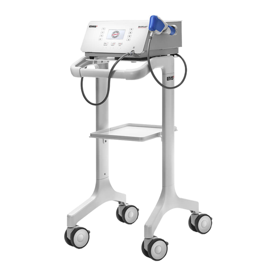
    2. INSTALLATION 2.1. BAUTEILE Je nach Konfiguration setzt sich das Gerät aus unter- schiedlichen Bauteilen zusammen. Abbildung 1 BEZEICHNUNG Konsole Handstück mit 15-mm-Applikator (Anwendungsteil) Applikatorset (siehe Details auf der nächsten Seite) Wagen - optional Handstückhalterset Netzkabel Gelflasche O-Ring-Wartungskit Kolben-Wartungskit...
  • Seite 88 10-mm-Applikator - Optional 15-mm-Applikator, Trigger - Optional 15-mm-Applikator, Fokus - Optional 25-mm-Applikator - Optional 5-mm-Applikator - Optional *EMS empfiehlt, den Applikator vor der Behandlung eines Patienten zu reinigen und zu desinfizieren. Abbildung 3 BEZEICHNUNG Anschluss für das Handstück (Anwendungsteil) Handstückhalter...
  • Seite 89: Konsole Aufstellen

    2.2. KONSOLE AUFSTELLEN 2.2.2. Installieren der Handstückhalterung am Gerät Stellen Sie die Konsole auf eine ebene und sta- 1. Verwenden Sie die mitgelieferten Schrauben und bile Fläche oder verwenden Sie den (optionalen) das Werkzeug, um den Handstückhalter am Gerät Wagen für das jeweilige Konsolenmodell. zu befestigen.
  • Seite 90: Konsole An Den Potenzialausgleichsleiter Anschliessen

    2. Platzieren Sie das Handstück am bereitgestellten 2.3. KONSOLE AN DEN Handstückhalter. POTENZIALAUSGLEICHSLEITER ANSCHLIESSEN Schließen Sie den Potenzialausgleichsleiter gemäß dem einrichtungsinternen Protokoll über die Busleiste auf der Rückseite der Konsole an. Das Potenzialausgleichskabel ist nicht in der Konsole enthalten. Der Potenzialausgleichsstecker wird verwendet, um Potenzialunterschiede zwischen medizinischen Geräten zu verhindern, die Mess- oder Behandlungsfehler verur- sachen könnten, wenn das medizinische Gerät Störungen...
  • Seite 91: Erste Schritte

    3. ERSTE SCHRITTE 3.1. GERÄT STARTEN Der Hauptschalter des Geräts muss jederzeit zugänglich sein, um das Gerät abschalten zu können. 1. Betätigen Sie den Hauptschalter auf der Rückseite zum Einschalten der Konsole. Abbildung 12 3.2. SCHNITTSTELLEN 3.2.1. Konsolenbildschirm 2500 Impulses SMART PROTOCOL Abbildung 13 BEZEICHNUNG...
  • Seite 92: Bedeutung

    TASTE BEDEUTUNG AKTION Mit dieser Taste können Sie den auf dem Bildschirm Minus-Taste angezeigten Wert verringern. Mit dieser Taste können Sie den auf dem Bildschirm Plus-Taste 2500 Impulses angezeigten Wert erhöhen. Mit diesen Tasten können Sie ein voreingestelltes Protokoll SMART PROTOCOL Voreingestellte Proto- auswählen.
  • Seite 93: Informationen Über Software Und Handstück (Nutzungszahl)

    Page 2 Abbildung 18 Abbildung 16 Spracheinstellungen werden Werkseinstellungen zurückgesetzt. Wenn Sie ein EMS garantiert keine Behandlung, wenn der Kol- USER-Protokoll gespeichert haben, wird es ben seine maximal empfohlene Impuls-Anzahl gelöscht. erreicht hat. 3. Drücken Sie auf , um zu bestätigen, dass Sie 4.
  • Seite 94: Ds Gerät Ausschalten

    4. Drücken Sie die Tasten oder , um die entsprechende Sprache auszuwählen. Abbildung 19 5. Um weitere Sprachen anzuzeigen, verwenden Sie die Taste , um weitere Sprachoptionen auf den folgenden Seiten anzuzeigen. 3.5. DS GERÄT AUSSCHALTEN 1. Betätigen Sie den Hauptschalter auf der Rückseite zum Ausschalten der Konsole Abbildung 20...
  • Seite 95: Behandlung

    Kopplungsgel, um optimale Ergebnisse zu erzie- Sie ihn an das Handstück an. len. Dank seiner speziellen Viskosität überträgt das EMS Gel die Stoßwellen ohne Leckage, um 7. Positionieren Sie den Patienten auf der Behandlungsbank. eine perfekte Übertragung während der gesam- 8.
  • Seite 96: Einstellen Des Drucks

    1. Vergewissern Sie sich, dass der O-Ring beim 4.2.2. Einstellen des Drucks Ersatzapplikator noch an seinem Platz ist. Wenn der O-Ring vom Applikator getrennt ist, ersetzen Sie ihn. Um die Stoßwellentiefe und die in das Gewebe übertragene Energie einzustellen, muss der Druck erhöht oder verringert werden.
  • Seite 97: Einstellen Der Impuls-Anzahl

    verwen- 2. Wählen Sie die Größe des zur Behandlung 4.2.4. Einstellen der Impuls-Anzahl deten Applikators . Um die Gesamtzahl der an den Patienten übertragenen Impulse anzupassen, erhöhen oder verringern Sie die Anzahl der Impulse. Die Anzahl der Impulse kann 5 mm 10 mm zwischen 500 und 5000 in Schritten von 500 eingestellt 15 mm...
  • Seite 98: Durchführen Der Behandlung

    Energiedichte der folgende Um die Behandlungseffizienz zu maximieren, empfehlen Bildschirm. Der QR-Code Ihres Konsolenbild- wir, das Handstück mit zwei Händen wie folgt auf zwei schirms führt Sie zu einer EMS-Website, die sich verschiedene Arten zu halten: mit dem GDT-Protokoll befasst. •...
  • Seite 99: Pausieren / Beenden Der Behandlung

    Abbildung 37 2. Wenn Sie die Behandlung beginnen und den Appli- kator im Behandlungsbereich bewegen, bitten Sie den Patienten, Ihnen zu sagen, wann die Behandlung unangenehm wird, und passen Sie die Geräteeinstel- lungen entsprechend an. Die manuell ausgeübte Applikationskraft variiert und hängt von der Indikation ab.
  • Seite 100: Voreingestellte Protokolle

    5. VOREINGESTELLTE PROTOKOLLE 5.1. BESCHREIBUNG DER VOREINGESTELLTEN PROTOKOLLE Sie können voreingestellte Protokolle als Ausgangspunkt verwenden, anstatt jede Einstellung manuell vorzunehmen. Voreingestellte Protokolle stehen zur Verfügung, um Ihnen zu helfen, die Behandlung zielgerichtet durchzuführen und die Effizienz zu erhöhen. Voreingestellte Protokolle sind in sechs Gruppen unterteilt: VOREINGESTELLTE WERKSEINSTELLUNGEN PROTOKOLLE...
  • Seite 101: Speichern Angepasster Voreingestellter Protokolle

    5.4. SPEICHERN ANGEPASSTER VOREINGESTELLTER PROTOKOLLE Sie können die Einstellungen, die Sie für ein bestimmtes voreingestelltes Protokoll vorgenommen haben, einfach speichern. 1. Um die neu angepassten Einstellungen für ein bestimmtes voreingestelltes Protokoll festzuhalten, halten Sie die Tasten gleichzeitig 2 Sekunden lang gedrückt. 2500 Impulses ENTHESOPATHY*...
  • Seite 102: Sondermodi

    6. SONDERMODI ANALGESIC [0 mJ/mm Es kann jeweils nur ein Sondermodus aktiviert werden. ANALGESIC [0 mJ/mm Alle mit den Sondermodi verbundenen Einstel- lungen sind voreingestellt und können nicht ge- 1000 Impulses 1000 ändert werden. Impulses SMART PROTOCOL SMART PROTOCOL 6.1. ANALGETIKUM-MODI Die Analgetika-Modi helfen den Ärzten, die Akzeptanz der Behandlung bei empfindlichen Patienten zu verbessern.
  • Seite 103: Ramp-Up-Modi

    ANALGESIC [0 mJ/mm ANALGESIC [0 mJ/mm 1000 1000 Impulses Impulses SMART PROTOCOL SMART PROTOCOL Abbildung 45 1. Drücken Sie vor Beginn der Behandlung oder nach einer Pause die Ramp-Up-Taste, um den Ramp-Up- Modus 1 zu aktivieren. Die LED zeigt an, dass der Modus aktiviert ist.
  • Seite 104: Burst-Modi

    6.3. BURST-MODI Verwenden Sie die Burst-Modi, um zu verhindern, dass der Patient eine Toleranz gegenüber bestimmten mecha- nischen Reizen entwickelt. Die Burst-Modi sind speziell dafür ausgelegt, während der Behandlung zwischen einer voreingestellten Frequenz und einer Maximalfrequenz zu wechseln. 6.3.1. Burst-Modus 1 Abbildung 47 Bei Verwendung des Burst-Modus 1 während der 1.
  • Seite 105 6.3.2. Burst-Modus 2 Der Burst-Modus 2 ermöglicht das manuelle Umschalten zwischen einer eingestellten Frequenz und einer Frequenz von 25 Hz. Abbildung 51 1. Drücken Sie die Burst-Taste zweimal, um den Burst- Modus 2 zu aktivieren. Die LED zeigt an, dass der Modus aktiviert ist.
  • Seite 106: Reinigung Und Desinfektion

    7. REINIGUNG UND DESINFEKTION 1. Demontieren Sie den Applikator, die Nase, die 7.1. HANDSTÜCK Blockiermutter und die O-Ringe. Wir empfehlen, das Handstück nach jeder Be- handlung zu reinigen und zu desinfizieren. 1. Reinigen und desinfizieren Sie mit Reinigungs- und Desinfektionstüchern, beispielsweise mit Surface Wipes Zero von Helvemed oder einem gleichwertigen...
  • Seite 107: Wartung

    Bajonett zu lösen. Abbildung 55 Der QR-Code, der auf Ihrem Konsolenbildschirm angezeigt wird, führt zu einer EMS-Website, über die Sie einen neuen Kolben bestellen können. Abbildung 58 Um den Kolben zu wechseln, gehen Sie wie folgt vor: 1.
  • Seite 108: Für 5-Mm-, 10-Mm- Und 15-Mm-Applikatoren

    5. Installieren Sie den neuen Kolben am Handstück. zu entfernen. 6. Bauen Sie das Handstück wieder zusammen. 8.1.2. Applikator-O-Ring EMS empfiehlt, die O-Ringe beim Kolbenwechsel ebenfalls zu wechseln. 8.1.2.1. Für 5-mm-, 10-mm- und 15-mm-Applikatoren 1. Demontieren Sie den Applikator. Abbildung 59 3.
  • Seite 109: Für 25-Mm- Und 40-Mm-Applikatoren

    8.1.2.2. Für 25-mm- und 40-mm-Applikatoren Abbildung 64 BEZEICHNUNG MENGE O-Ringe Abbildung 68 Applikator BEZEICHNUNG MENGE Nase Nase O-Ringe 1. Legen Sie den O-Ring 1a auf den Applikator. Applikator Mutter 2. Legen Sie den O-Ring 1b auf den Applikator. 1. Entfernen Sie den Applikator vom Handstück. Abbildung 65 3.
  • Seite 110 3. Fit the Setzen Sie den großen Schraubenschlüssel 6. Entfernen Sie die Nase. am Applikator an und halten die Halterung mit der Hand fest. Drehen Sie den Schraubenschlüssel, um die Mutter zu lösen. Abbildung 74 Abbildung 71 7. Entfernen Sie den zweitgrößten O-Ring. 4.
  • Seite 111 9. Um die O-Ringe zu montieren, setzen Sie den O-Ring 12. Platzieren Sie den Applikator auf die Nase. in die Nut des Applikators. Abbildung 77 Abbildung 81 Stellen Sie sicher, dass der O-Ring richtig positio- 13. Legen Sie den O-Ring auf den Applikator. niert ist.
  • Seite 112: Konsole

    8.2.1. Sicherungen auswechseln 5. Setzen Sie das Sicherungsfach wieder ein. 1. Schalten Sie das Gerät aus. 6. Wenn die Sicherungen erneut durchbrennen, wenden Sie sich bitte an Ihr zugelassenes EMS-Service- 2. Trennen Sie das Netzkabel auf der Rückseite der zentrum. Konsole.
  • Seite 113: Kompatibilität Mit Der Dolorclast ® Produktpalette

    Radial Shock Waves sollte nicht neben einem anderen Gerät oder auf einem anderen ® Gerät gestapelt verwendet werden. Falls die Verwendung in unmittelbarer Nähe eines Geräts bzw. auf oder neben einem anderen Gerät unvermeidbar ist, muss die normale Betriebstüchtigkeit des DOLORCLAST ® der entsprechenden Konfiguration geprüft werden.
  • Seite 114 Leitfaden und Herstellererklärung – Elektromagnetische Emissionen Das DOLORCLAST Radial Shock Waves ist für den Betrieb in der nachstehend beschriebenen elektromagneti- ® schen Umgebung bestimmt. Der Kunde oder Anwender des DOLORCLAST Radial Shock Waves muss sicher- ® stellen, dass es in einer solchen Umgebung verwendet wird.
  • Seite 115 Radial Shock Waves muss sicher- ® stellen, dass es in einer solchen Umgebung verwendet wird. Tragbare und mobile HF-Kommunikationsgeräte sollten nicht näher an den Teilen des DOLORCLAST Radial Shock Waves, ® einschließlich der Kabel, verwendet werden, als der empfohlene Schutzabstand beträgt, der mit der Formel zur Berechnung der Senderfrequenz ermittelt wird.
  • Seite 116 MHz, 24,89 - 24,99 MHz, 28,0 - 29,7 MHz und 50,0 - 54,0 MHz. Tabelle 6 Konforme Kabel und konformes Zubehör Der Gebrauch anderer Zubehörteile oder Kabel, die nicht von EMS empfohlen oder als Ersatzteile geliefert werden, kann zu erhöhten Emissionen oder verminderter Störfestigkeit dieses Produkts führen. KABEL UND...
  • Seite 117: Produkt Entsorgen

    Die Annahme kontaminierter Geräte oder konta- Material Agreement) zu erhalten. minierten Zubehörs zur Reparatur kann abge- lehnt werden. Wenn Sie Ihr Produkt direkt an das autorisierte EMS-Ser- vicezentrum senden, geben Sie bitte den Namen des Händlers an, um die Bearbeitung zu vereinfachen. 15. GARANTIE Die Garantie ist ungültig, wenn das Gerät mit nicht origi-...
  • Seite 118: Technische Beschreibung

    16. TECHNISCHE BESCHREIBUNG HERSTELLER EMS ELECTRO MEDICAL SYSTEMS SA, CH-1260 Nyon, Schweiz MODELL DOLORCLAST Radial Shock Waves ® STROMVERSORGUNG 100-240 VAC / 50-60 Hz / 500 VA KLASSIFIZIERUNG EN 60601-1 System: Klasse I Anwendungsteil Typ BF FUNKKOMMUNIKATION RFID 13,56 MHz KLASSIFIZIERUNG MDD 93/42 EEC Konsole, Handstück: Klasse IIb...
  • Seite 119: Symbole

    17. SYMBOLE Herstellerlogo DOLORCLAST Produktname RADIAL SHOCK WAVES Hersteller Katalognummer Seriennummer Herstellungsdatum Eingangsleistung Gefahr eines Stromschlags CE-Symbol, bezieht sich auf die Richtlinie 93/42/EWG, einschließlich EN 60601-1 und EN 60601-1-2 Das Gerät erfordert eine Schutzerdung Siehe Bedienungsanleitung Entsorgung von gebrauchten elektrischen und elektronischen Geräten (gilt für Länder der Europäischen Union und andere europäische Länder mit einem separaten...
  • Seite 120 Siehe Bedienungsanleitung Recyclefähig EMS-Webseite Zerbrechlich Vor Regen geschützt aufbewahren Inhalt Vertikale Position Verfalldatum Maximale Luftfeuchtigkeit: 85 % Transporttemperaturen zwischen +1 °C und +30 °C...
  • Seite 121: Anhang

    18. ANHANG APPLIKATOREN INDIKATIONEN 15 mm, 15 mm, 5 mm 10 mm 15 mm 25 mm 40 mm Fokus Auslöser Tendopathien (bei der Erstdiagnose und bei    chronischen Tendopathien) Capsulitis (z. B. Engpasssyndrome an der   Schulter) Triggerpunkte und myofasziale Schmerzsyn- ...
  • Seite 124 Fax +49 89 42 71 61 60 e-mail: info@ems-france.fr e-mail: welcome@ems-ch.com e-mail: info@ems-ch.de SPAIN ITALY Manufacturer EMS Electro Medical Systems España SLU EMS Italia S.r.l c/Tomás Bretón, 50-52, 2ª planta EMS Electro Medical Systems SA Via Pisacane 7/b E-28045 Madrid Ch. de la Vuarpillière 31 I-20016 Pero (MI) Tlf.

Inhaltsverzeichnis