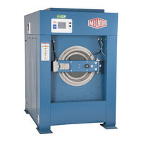
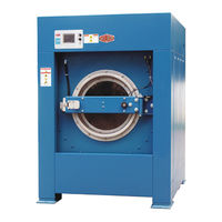
Inhaltsverzeichnis
-
-
Machine Description and Identification
10
-
About this Manual and Your Milnor
10
-
-
-
Machine Identification
10
-
-
Figure 1 Machine Data Plate
10
-
-
Safety - Suspended Washer Extractors
11
-
Safety Alert Messages-Internal Electrical and Mechanical Hazards
11
-
Safety Alert Messages-Cylinder and Processing Hazards
11
-
Safety Alert Messages-Unsafe Conditions
13
-
Damage and Malfunction Hazards
13
-
Hazards Resulting from Inoperative Safety Devices
13
-
Hazards Resulting from Damaged Mechanical Devices
13
-
-
Careless Operation Hazards-Vital Information for Operator Personnel (See also Operator Hazards Throughout Manual)
14
-
Careless Servicing Hazards-Vital Information for Service Personnel (See also Service Hazards Throughout Manuals)
14
-
Prevent Damage from Chemical Supplies and Chemical Systems
15
-
How Chemical Supplies Can Cause Damage
15
-
Dangerous Chemical Supplies and Wash Formulas
15
-
Incorrect Configuration or Connection of Equipment
16
-
Figure 2 Incorrect Configurations that Let the Chemical Supply Go in the Ma
17
-
Equipment and Procedures that Can Prevent Damage
18
-
Use the Chemical Manifold Supplied
18
-
Figure 3 Incorrect Configurations that Let the Chemical Supply Go in the Ma
18
-
Figure 4 Examples of Manifolds for Chemical Tubes. Your Equipment Can Look
18
-
-
Do Not Let a Vacuum Occur
19
-
Flush the Chemical Tube with Water
19
-
Put the Chemical Tube Fully below the Inlet
19
-
-
Figure 5 a Configuration that Prevents Flow in the Machine When the Pump Is off (if the Chemical Tube and Tank Have no Pressure)
19
-
-
-
Guards and Related Components
21
-
Filters, Screens, and Sensitive Components
21
-
Table 1 Guards and Related Components
21
-
Table 2 Filters, Screens, and Sensitive Components
21
-
Components that Become Worn
22
-
-
Table 3 Components that Become Worn
22
-
-
Mechanisms and Settings
23
-
Table 6 Mechanisms and Settings
23
-
How to Remove Contamination
24
-
Table 7 Contamination Types, Cleaning Agents, and Procedures
24
-
Lubricant Identification
25
-
-
Procedures for Bearing Components Connected to a Grease Plate
26
-
-
Figure 6 Motor Grease Maintenance Conditions
27
-
How to Show the Maintenance on a Calendar
28
-
Table 9 Motor Grease Intervals and Quantities
28
-
Maintenance Components-Machines and Controls Group
29
-
How to Examine V-Belts and Pulleys
29
-
Figure 7 Belt and Pulley Conditions to Look for
29
-
Table 10 Where to Put Marks on a Calendar
29
-
Figure 8 How to Adjust Belt Tension on a Machine that Uses Spring Tension
30
-
-
-
Figure 9 Electric Box and Inverter. These Are Examples. Your Machine Can Look
31
-
Water and Steam Devices
32
-
Figure 10 Chemical Inlet Manifolds for Chemical Pump Systems. See Caution
32
-
Figure 11 Soap Chute and Optional 5-Compartment Supply Injector. These Are Ex
32
-
Figure 12 Air Tube for the Water Level Sensor. These Are Examples. Your Ma- Chine Can Look Different
33
-
Figure 13 Water Pressure Regulator for Chemical Flush. These Are Examples
33
-
How to Examine Compressed Air Mechanisms
34
-
Figure 14 Steam Inlet Strainer. These Are Examples. Your Machine Can Look Different
34
-
Figure 15 Compressed Air Inlet Strainers. These Are Examples. Your Machine Can
34
-
Figure 16. Self-Purging Air Line Filter to Remove Moisture and Other Contamination. These Are Examples. Your Machine Can Look Different
35
-
Figure 17 Compressed Air Mechanisms These Are Examples. Your Machine Can Look Different
36
-
Photoeyes and Proximity Switches
37
-
How to Do a Test of Emergency Stop Mechanisms
37
-
Figure 18 Speed Sensor (Photoeye) on some Machines
37
-
Maintenance Components-Large Extractors
38
-
Lubricant Maintenance for Grease-Filled Drive Bearings
38
-
Figure 19 Grease Ports for Grease-Only Bearing Assembly
38
-
Lubricant Maintenance for Non-Drive Components
39
-
About the Shock Absorbers
39
-
-
Figure 20 Grease Ports for Door-Open Pocket Models. These Are Examples
39
-
-
-
-
-
-
-
-
-
-
-
-
-
-
-
-
-
-
-
-
-
-
-
-
-
-
-
-
-
-
-
-
-
-
-
-
-
-
-
-
-
-
-
-
-
-
-
-
-
-
-
-
-
-
-
-
-
-
-
-
-
-
-
-
-
-
-
-
-
-
-
-
-
-