
Verwandte Anleitungen für Stahl 8018 Serie


Inhaltszusammenfassung für Stahl 8018 Serie
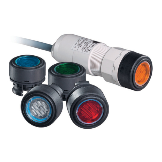
- Seite 1 Betriebsanleitung Additional languages r-stahl.com LED-Leuchtdrucktaster für Schalttafeleinbau Reihe 8018/3...
-
Seite 2: Inhaltsverzeichnis
Inhaltsverzeichnis Inhaltsverzeichnis Allgemeine Angaben....................3 Hersteller......................3 Zu dieser Betriebsanleitung .................3 Weitere Dokumente .....................3 Konformität zu Normen und Bestimmungen ............3 Erläuterung der Symbole ..................4 Symbole in der Betriebsanleitung ................4 Symbole am Gerät ....................4 Sicherheit ......................5 Bestimmungsgemäße Verwendung..............5 Qualifikation des Personals .................5 Restrisiken ......................6 Transport und Lagerung ..................7 Montage und Installation..................8 Montage / Demontage ..................8... -
Seite 3: Allgemeine Angaben
▶ Betriebsanleitung dem Bedien- und Wartungspersonal jederzeit zugänglich machen. ▶ Betriebsanleitung an jeden folgenden Besitzer oder Benutzer des Geräts weitergeben. ▶ Betriebsanleitung bei jeder von R. STAHL erhaltenen Ergänzung aktualisieren. ID-Nr.: 129916 / 8018602300 Publikationsnummer: 2022-06-28·BA00·III·de·04 Die Originalbetriebsanleitung ist die englische Ausgabe. -
Seite 4: Erläuterung Der Symbole
Erläuterung der Symbole Erläuterung der Symbole Symbole in der Betriebsanleitung Symbol Bedeutung Hinweis zum leichteren Arbeiten Gefahrensituation, die bei Nichtbeachtung der GEFAHR! Sicherheitsmaßnahmen zum Tod oder zu schweren Verletzungen mit bleibenden Schäden führen kann. Gefahrensituation, die bei Nichtbeachtung der WARNUNG! Sicherheitsmaßnahmen zu schweren Verletzungen führen kann. -
Seite 5: Sicherheit
Normen und Bestimmungen umfasst. Für Tätigkeiten in explosionsgefährdeten Bereichen sind weitere Kenntnisse erforderlich! R. STAHL empfiehlt einen Kenntnisstand, der in folgenden Normen beschrieben wird: • IEC/EN 60079-14 (Projektierung, Auswahl und Errichtung elektrischer Anlagen) • IEC/EN 60079-17 (Prüfung und Instandhaltung elektrischer Anlagen) •... -
Seite 6: Restrisiken
Gerät nur in Originalverpackung oder gleichwertiger Verpackung transportieren. ▶ Verpackung und Gerät auf Beschädigung prüfen. Beschädigungen umgehend an R. STAHL melden. Beschädigtes Gerät nicht in Betrieb nehmen. ▶ Gerät in Originalverpackung, trocken (keine Betauung), in stabiler Lage und sicher vor Erschütterungen lagern. -
Seite 7: Verletzungsgefahr
Transport und Lagerung 3.3.2 Verletzungsgefahr Stromschlag Während des Betriebs und der Instandhaltung liegen zeitweise hohe Spannungen am Gerät an, daher muss während der Installation das Gerät spannungsfrei geschaltet sein. Durch Kontakt mit Leitungen, die Spannung führen, können Personen schwere Stromschläge und damit Verletzungen erleiden. ▶... -
Seite 8: Montage Und Installation
Montage und Installation Montage und Installation Montage / Demontage ▶ Gerät sorgfältig und unter Beachtung der Sicherheitshinweise (siehe Kapitel "Sicherheit") sowie der Projektierungsvorgaben montieren. ▶ Folgende Einbaubedingungen und Montageanweisungen genau durchlesen und exakt befolgen. 5.1.1 Gebrauchslage Die Gebrauchslage ist beliebig. Einbau der Geräte 8018/3.. -
Seite 9: Einbau Der Geräte In Die Schalttafel
Montage und Installation Einbau der Geräte in die Schalttafel ▶ 04928E00 Leuchtdrucktastervorsatz (1) in die Einbauwand (3) stecken und arretieren. Dabei auf exakten Sitz der Dichtung (2) achten. ▶ Leuchtdrucktaster von der Rückseite auf den Leuchtdrucktastervorsatz (1) stecken. Sicherstellen, dass Leuchtdrucktaster und Leuchtvorsatz (1) fest in der Einbauwand (3) sitzen. -
Seite 10: Inbetriebnahme
▶ Gerät regelmäßig auf Schäden sowie sachgemäßen Betrieb kontrollieren. Reparatur ▶ Reparaturen am Gerät nur durch R. STAHL durchführen lassen. ▶ Beschädigte Geräteteile bzw. ein beschädigtes Gerät sofort austauschen, um die elektrische Sicherheit und den Explosionsschutz des Systems zu gewährleisten. -
Seite 11: Rücksendung
▶ Rücksendung bzw. Verpackung der Geräte nur in Absprache mit R. STAHL durchführen! Dazu mit der zuständigen Vertretung von R. STAHL Kontakt aufnehmen. Für die Rücksendung im Reparatur- bzw. Servicefall steht der Kundenservice von R. STAHL zur Verfügung. ▶ Kundenservice persönlich kontaktieren. -
Seite 12: 13.1 Technische Daten
Anhang A Anhang A 13.1 Technische Daten Explosionsschutz Global (IECEx) Gas und Staub IECEx PTB 07.0011X Ex e 8018/31. Ex db mb IIC T6 Gb Ex i 8018/32. Ex db mb ia IIC T6 Gb Ex tb IIIC T80 °C Db Europa (ATEX) Gas und Staub PTB 02 ATEX 2129 X... - Seite 13 über Farbfilter (im Lieferumfang enthalten) Montage / Installation Anschluss Leitung H05 6 x 0,75 mm , 6-polig Leitungslänge 6 m (Standard) Weitere technische Daten, siehe r-stahl.com. 129916 / 8018602300 LED-Leuchtdrucktaster 2022-06-28·BA00·III·de·04 für Schalttafeleinbau Reihe 8018/3...
-
Seite 14: 14.1 Maßangaben / Befestigungsmaße
Anhang B Anhang B 14.1 Maßangaben / Befestigungsmaße Maßzeichnungen (alle Maße in mm [Zoll]) – Änderungen vorbehalten Ø [ 1,50] Ø 38,50 Ø [ 1,52] Ø 42 [ 1, 65] 36,50 Ø [ 1,44] Ø 03315E00 04488E00 Reihe 8018/3 Bohrbild: LED-Leuchtdrucktaster Aneinanderreihung mehrerer Schalttafeleinbaugeräte mit... - Seite 15 Operating instructions Additional languages r-stahl.com LED illuminated pushbutton for panel mounting Series 8018/3...
- Seite 16 Contents Contents General Information .....................3 Manufacturer......................3 About these Operating Instructions..............3 Further Documents ....................3 Conformity with Standards and Regulations............3 Explanation of Symbols ..................4 Symbols used in these Operating Instructions.............4 Symbols on the Device ..................4 Safety........................5 Intended Use......................5 Personnel Qualification ..................5 Residual Risks .....................6 Transport and Storage ..................7 Mounting and Installation ..................8 Mounting/Dismounting ..................8...
-
Seite 17: General Information
Make the operating instructions accessible to operating and maintenance staff at all times. ▶ Pass the operating instructions on to each subsequent owner or user of the device. ▶ Update the operating instructions every time R. STAHL issues an amendment. ID no.: 129916 / 8018602300 Publication code: 2022-06-28·BA00·III·en·04... -
Seite 18: Explanation Of Symbols
Explanation of Symbols Explanation of Symbols Symbols used in these Operating Instructions Symbol Meaning Handy hint for making work easier Dangerous situation which can result in fatal or severe injuries DANGER! causing permanent damage if the safety measures are not complied with. -
Seite 19: Safety
Specialists who perform these activities must have a level of knowledge that meets applicable national standards and regulations. Additional knowledge is required for any activity in hazardous areas! R. STAHL recommends having a level of knowledge equal to that described in the following standards: •... -
Seite 20: Residual Risks
▶ Transport the device only in its original packaging or in equivalent packaging. ▶ Check the packaging and the device for damage. Report any damage to R. STAHL immediately. Do not commission a damaged device. ▶ Store the device in its original packaging in a dry place (with no condensation), and make sure that it is stable and protected against the effects of vibrations and knocks. -
Seite 21: Risk Of Injury
Transport and Storage 3.3.2 Risk of Injury Electric shock During operation and maintenance, the device has high voltage applied to it at times. Because of this, the device must be de-energised during installation. Persons coming into contact with electrical lines carrying voltage can suffer severe electric shocks and, consequently, injuries. -
Seite 22: Mounting And Installation
Mounting and Installation Mounting and Installation Mounting/Dismounting ▶ Mount the device carefully and only in accordance with the safety notes (see "Safety" chapter) and the project engineering specifications. ▶ Read through the following installation conditions and assembly instructions carefully and follow them precisely. -
Seite 23: Installation Of Devices Into The Panel
Mounting and Installation Installation of Devices into the Panel ▶ 04928E00 Push the illuminated pushbutton actuator (1) into the installation wall (3) and lock it in position. Ensure that the seal (2) is seated precisely when doing so. ▶ Push the illuminated pushbutton from the reverse side onto the illuminated pushbutton actuator (1). -
Seite 24: Commissioning
Regularly check the device for damage as well as proper operation. Repair ▶ Repair work on the device must be performed only by R. STAHL. ▶ Promptly replace any damaged parts of the device or a damaged device to ensure the electrical safety and explosion protection of the system. -
Seite 25: Returning The Device
Returning the Device ▶ Only return or package the devices after consulting R. STAHL! Contact the responsible representative from R. STAHL. R. STAHL's customer service is available to handle returns if repair or service is required. ▶ Contact customer service personally. ▶... -
Seite 26: Appendix A
Appendix A Appendix A 13.1 Technical Data Explosion protection Global (IECEx) Gas and dust IECEx PTB 07.0011X Ex e 8018/31. Ex db mb IIC T6 Gb Ex i 8018/32. Ex db mb ia IIC T6 Gb Ex tb IIIC T80 °C Db Europe (ATEX) Gas and dust PTB 02 ATEX 2129 X... - Seite 27 Red, yellow, green, blue, white using colour filter (included in delivery) Mounting/installation Connection H05 6 x 0.75 mm conductor , 6-pole Conductor length 6 m (standard) For further technical data, see r-stahl.com. 129916 / 8018602300 LED illuminated pushbutton 2022-06-28·BA00·III·en·04 for panel mounting Series 8018/3...
-
Seite 28: Appendix B
Appendix B Appendix B 14.1 Dimensions/Fastening Dimensions Dimensional drawings (all dimensions in mm [inch]) – Subject to change Ø [ 1,50] Ø 38,50 Ø [ 1,52] Ø 42 [ 1, 65] 36,50 Ø [ 1,44] Ø 03315E00 04488E00 Series 8018/3 Drilling hole pattern: LED illuminated pushbutton Aligning several panel mounting devices...